EP0415233B1 - Verfahren zum Festmachen einer Vorrichtung an einem Zelt, Vorrichtung zum Festmachen an einem Zelt und Zelt - Google Patents
Verfahren zum Festmachen einer Vorrichtung an einem Zelt, Vorrichtung zum Festmachen an einem Zelt und Zelt Download PDFInfo
- Publication number
- EP0415233B1 EP0415233B1 EP90115985A EP90115985A EP0415233B1 EP 0415233 B1 EP0415233 B1 EP 0415233B1 EP 90115985 A EP90115985 A EP 90115985A EP 90115985 A EP90115985 A EP 90115985A EP 0415233 B1 EP0415233 B1 EP 0415233B1
- Authority
- EP
- European Patent Office
- Prior art keywords
- anchoring
- canvas
- bracket
- attachment
- tent
- Prior art date
- Legal status (The legal status is an assumption and is not a legal conclusion. Google has not performed a legal analysis and makes no representation as to the accuracy of the status listed.)
- Expired - Lifetime
Links
- 238000000034 method Methods 0.000 title claims description 13
- 238000004873 anchoring Methods 0.000 claims description 96
- 239000000463 material Substances 0.000 claims description 10
- 238000003780 insertion Methods 0.000 claims description 7
- 230000037431 insertion Effects 0.000 claims description 7
- 239000004744 fabric Substances 0.000 claims description 6
- 230000000717 retained effect Effects 0.000 claims description 5
- 239000011248 coating agent Substances 0.000 claims description 3
- 238000000576 coating method Methods 0.000 claims description 3
- 229920001971 elastomer Polymers 0.000 description 12
- 239000004033 plastic Substances 0.000 description 7
- 229920003023 plastic Polymers 0.000 description 7
- 238000004026 adhesive bonding Methods 0.000 description 3
- 239000003292 glue Substances 0.000 description 3
- 238000000465 moulding Methods 0.000 description 2
- 238000009958 sewing Methods 0.000 description 2
- 238000005452 bending Methods 0.000 description 1
- 239000012141 concentrate Substances 0.000 description 1
- 239000002537 cosmetic Substances 0.000 description 1
- 238000005336 cracking Methods 0.000 description 1
- 229920002457 flexible plastic Polymers 0.000 description 1
- 230000001771 impaired effect Effects 0.000 description 1
- 230000000977 initiatory effect Effects 0.000 description 1
- 231100000989 no adverse effect Toxicity 0.000 description 1
- 229920002635 polyurethane Polymers 0.000 description 1
- 239000004814 polyurethane Substances 0.000 description 1
- 238000010008 shearing Methods 0.000 description 1
- 239000007787 solid Substances 0.000 description 1
- 238000003466 welding Methods 0.000 description 1
- 230000037303 wrinkles Effects 0.000 description 1
Images


Classifications
-
- E—FIXED CONSTRUCTIONS
- E04—BUILDING
- E04H—BUILDINGS OR LIKE STRUCTURES FOR PARTICULAR PURPOSES; SWIMMING OR SPLASH BATHS OR POOLS; MASTS; FENCING; TENTS OR CANOPIES, IN GENERAL
- E04H15/00—Tents or canopies, in general
- E04H15/02—Tents combined or specially associated with other devices
- E04H15/06—Tents at least partially supported by vehicles
-
- B—PERFORMING OPERATIONS; TRANSPORTING
- B60—VEHICLES IN GENERAL
- B60P—VEHICLES ADAPTED FOR LOAD TRANSPORTATION OR TO TRANSPORT, TO CARRY, OR TO COMPRISE SPECIAL LOADS OR OBJECTS
- B60P3/00—Vehicles adapted to transport, to carry or to comprise special loads or objects
- B60P3/32—Vehicles adapted to transport, to carry or to comprise special loads or objects comprising living accommodation for people, e.g. caravans, camping, or like vehicles
- B60P3/34—Vehicles adapted to transport, to carry or to comprise special loads or objects comprising living accommodation for people, e.g. caravans, camping, or like vehicles the living accommodation being expansible, collapsible or capable of rearrangement
- B60P3/341—Vehicles adapted to transport, to carry or to comprise special loads or objects comprising living accommodation for people, e.g. caravans, camping, or like vehicles the living accommodation being expansible, collapsible or capable of rearrangement comprising flexible elements
- B60P3/343—Hoods for caravans
-
- E—FIXED CONSTRUCTIONS
- E04—BUILDING
- E04H—BUILDINGS OR LIKE STRUCTURES FOR PARTICULAR PURPOSES; SWIMMING OR SPLASH BATHS OR POOLS; MASTS; FENCING; TENTS OR CANOPIES, IN GENERAL
- E04H15/00—Tents or canopies, in general
- E04H15/02—Tents combined or specially associated with other devices
- E04H15/06—Tents at least partially supported by vehicles
- E04H15/08—Trailer awnings or the like
Definitions
- the present invention concerns a method for the attachment of an anchoring bracket onto the canvas of a tent or an awning.
- the invention further concerns an anchoring bracket for the attachment onto a piece of tent canvas and an awning with a beading along one edge adapted for removable mounting onto a caravan.
- Anchoring brackets of this general kind are used in connection with awnings for caravans, i.e. tents which may be arranged to form a compartment, wherein a longitudinal side of the caravan forms one wall, and wherein the tent is anchored to and supported onto the caravan.
- This kind of tent is quite popular and convenient in use, since it is possible to utilize the caravan for support and anchoring of the tent canvas and of the ridge poles, making it easy to design a tent, which is easily pitched and easily stroken, is spaceous and may serve as an awning or front porch at the caravan.
- the beading along the edge of the tent is conveniently manufactured by folding back a strip-like region of fabric along the edge of the tent and sewing or adhering the folded portion flat down onto the unfolded fabric portion to form a casing, which may enclose a beading core, e.g. a flexible rod, which may conveniently be permanently enclosed in or confined in the casing.
- a beading core e.g. a flexible rod
- anchoring eyelets are supplied as loose accessories so that each consumer, having made his choice of combination caravan and awning, must screw anchoring eyelets onto the caravan. This represents, on one hand, a craftsman-like procedure, which a consumer might rather not have to perform, and which he may be incapable of carrying out to a satisfactory result. Secondly it represents an intrusive operation in the outside wall of the caravan, which may be disfiguring and highly undesirable, e.g. in case the caravan should later be used in combination with a different awning.
- DE-A-37 36 537 discloses an anchoring bracket which is intended for being supplied as a loose part, and which may be supported by the caravan hollow profile by inserting an angled tongue on the bracket into the hollow profile longitudinal slit.
- This prior art bracket is neither intended for nor suitable for attachment to the awning canvas, and the user of the awning will, therefore, have to undertake separate operations to place or remove it, respectively, when pitching or striking the awning, respectively.
- the anchoring eyelets be attached to the canvas of the tent adjacent the beading edge in order to utilize the hollow profile for anchoring the ridge poles, eliminating all other fittings or brackets on the side of the caravan.
- One solution of the prior art comprises a rubber pad with an anchoring eyelet and a flexible region intended to be glued onto the tent canvas.
- the pad is flat and generally rectangular, except for a rounding of the corners around the anchoring eyelet.
- This solution has not been successful on the market. This is believed to be attributable to a number of drawbacks inherent in the design.
- the rubber pad is flat and has to be glued along one edge to the tent canvas adjacent the beading.
- the pad In the erected or in the pitched state with the canvas in the tent stretched in a direction close to horisontal away from the approximately vertical side of the caravan, the pad is likely to be bent close to a right angle (90°) and it must therefor be constructed of a relatively soft type of rubber so that it will not be torn off in the glued attachment.
- the pad By making the pad soft, the pad will, however, be incapable of providing a perfectly rigid support for the ridge pole. Insufficient support involves the danger of hitting the sides of the caravan with the ridge pole hooks with the danger of damaging the caravan wall surface.
- the method involving the attachment of the rubber pad by gluing it to the tent canvas surface is difficult to carry out to produce a well defined result, involving e.g. the danger that the glue adheres undesired parts, e.g. adhering a larger portion of the pad than desired, or glue seeping through the canvas of the tent adhering other regions of the tent canvas together than those intended.
- the tent canvas may be stretched by forces applied onto the pad so as to be deformed around the region of attachment, and e.g. the ribbon forming the casing may, in case the rubber pad is glued to one side of this ribbon, be pulled so as to travel around the beading core to be deformed.
- Deformations in the tent canvas are more than a simple cosmetic disadvantage as they are likely to interfere with the insertion of the beading edge along the hollow profile.
- the insertion may be a difficult procedure anyway, and this procedure may be even more difficult or totally impossible if the fabric forms folds or wrinkles, is deformed, contains glue residue, or in case the rubber scrapes along the outer surfaces of the hollow profile, causing added friction. It is of utmost importance that this insertion is not impaired in any way.
- the insertion process during which the rubber pad is likely to scrape along the caravan sides, may involve the danger of tearing off the pad and there may be a risk that rubber material tends to come off onto the caravan side, in particular for such types of rubber that are well suited for gluing.
- the anchoring bracket is provided in its region below the anchoring eyelet with a soft, compliant coating intended to serve as a sole, said sole preferably comprising material with a higher coefficient of friction than the remaining part of the anchoring bracket.
- the anchoring bracket is formed of a flat piece of flexible material contoured with a wide base line adjacent the zone of attachment and with sides converging or tapering in the direction towards the anchoring eyelet. This provides a desirable transfer of forces applied onto the eyelet to the zone of attachment and makes the bracket tend to slip aside in case it meets obstacles adjacent the hollow profile during the insertion process.
- the anchoring eyelet comprises a total of four eyelets oriented along two axes parallel to the plane of the sole surface and mutually perpendicular.
- the ridge pole hooks may be inserted in directions so as to obtain the best possible support for all directions or attitudes of the hollow profile at the region adjacent the anchoring bracket, which is advantageous as the hollow profile may extend vertically, horisontally or in oblique angles.
- the sole is attached to the remaining part of the anchoring bracket by a stud or pivot inserted into a sleeve in order to make it pivotable with a pivot axis perpendicular to the sole surface.
- figure 1 showing the arrangement of a caravan and the poles as they would be positioned in the erected or pitched awning, the canvas and the guy ropes of the tent being omitted from the figure in order to illustrate clearly the arrangement of the underlying parts.
- the figure shows a caravan 1 being provided along a portion of the edge of one side wall towards the roof and towards part of the front wall as well as part of the rear wall, respectively, with a hollow profile 2 extending from the profile front end 3 until the profile rear end 4.
- a framework of tent poles 5 is erected with anchorings to the caravan at three points 7 in a way to be explained in more detail below.
- FIG 2 To the left hand side of figure 2 the portion of the caravan 1 with the hollow profile 2 is shown.
- the awning canvas 10 is along the edge intended to be attached to a caravan provided with a beading.
- the beading is formed by folding a ribbonlike length of fabric 11 along a longitudinal folding line, stitching it together at the stitching 13 so as to form a casing and stitching it to the edge of the tent canvas 10 with two stitchings 14 and 15 so as to embrace the tent canvas edge.
- a beading core 12, e.g. a flexible plastic rod, has been inserted into the casing.
- the slit 8 in the hollow profile 2 is so narrow that the folded edge ribbon 11 with the beading core 12 is retained therein once it has been introduced therein.
- the hollow profile 2 is illustrated in figure 2 as mounted onto the caravan side wall adjacent the top edge, but it could alternatively and equally well be mounted on the caravan roof adjacent the side wall. The invention is obviously equally well applicable in either case.
- the awning canvas is attached by introducing an end of the beading through the open profile front end 3 or alternatively the open profile rear end 4 and pulling it with the canvas 10 along the entire length of the profile, whereafter the canvas is attached thereto in a rigid and sealed manner.
- Figure 2 further shows a section through an anchoring bracket 20 attached by the border stitching 15 to the tent canvas and to both sides of the folded edge ribbon 11.
- the anchoring bracket 20 comprises a flexible, flat piece 21 formed so that an upper portion hereof may lie flatly onto the tent canvas 10 while the opposite portion lies parallel to the caravan side wall.
- the anchoring bracket 20 is formed with a protrusion 23 adapted for contacting the caravan outside and serving as an contact sole.
- the anchoring bracket is provided on the side opposite the sole 23 with a thickened region 24 and with an anchoring eyelet formed essentially of a plateau 25 parallel to the sole contact surface and with a number of side ribs 26 as it will be explained in more detail below.
- a tent pole or ridge pole 5 is attached by inserting a hook 6 mounted permanently in the pole end through the anchoring eyelet.
- the pole 5 illustrated in figure 2 will be forced against the caravan side wall, the friction between the sole 23 and the caravan side wall being generally sufficient to retain the anchoring bracket 20 in a stationary position.
- the flat piece 21 must have a sufficient length so as not to be stressed by the force from the pole. Otherwise this force could cause an unnecessary stress onto the tent canvas, reducing also the friction forces.
- the bracket according to the invention has a length so that the sole of the anchoring bracket in the flat state extends beyond the tent canvas beading. An additional requirement is that the length must be sufficient to allow bending of the anchoring bracket as shown in figure 2 without causing significant forces onto the tent canvas.
- FIG 3 shows the stitching 13 closing the casing with the beading core 12 (shown in phantom), the edge of the tent canvas 16 (in phantom), a middle stitching 14 holding together the edge ribbon and the tent canvas and a stitching 15 to the right holding together both sides of the edge ribbon, the tent canvas and the anchoring bracket 20.
- the region of the anchoring bracket where it is attached to the tent canvas - in this embodiment a portion of the stitching 15 - will be referred to as the zone of attachment 18.
- the casing could alternatively have been made by folding back a marginal region of the tent canvas and sewing these two portions together, but according to the most preferred embodiment the casing is made as shown in figure 3 from a separate length of material so that a piece of material, which is particularly strong and smooth, may be selected in order that the edge is sturdy and may easily be slipped into the hollow profile.
- the casing material may comprise a woven, plastic-coated length of fabric or a non-woven, granulated length of plastic with a low friction outer surface.
- figure 3 shows an attachment of the anchoring bracket by the stitching 15
- other ways of attachment could obviously be conceived within the frames of the invention.
- the particular layout of seams in the edge stitchings can be selected by those skilled in the art in various ways and the anchoring bracket may be adhered in any of the edge stitching seams or in any combination hereof.
- Other possibilities could be an attachment of the anchoring bracket by separate stitching, by welding or by riveting.
- the points of attachment should preferably be located between edge stitching seams.
- the zone of attachment should in any case extend essentially linearly and essentially parallel to the casing in order to ensure that the transfer of forces to the tent canvas affects the tent canvas in as gentle a fashion as possible.
- Figure 3 further shows how the anchoring bracket 20 has an essentially trapezoid contour with a wide base-line edge 30 along the stitching and inclined side edges 31 converging or tapering in the direction towards the anchoring eyelet shown to the left in the figure.
- the anchoring bracket becomes somewhat more flexible along the side edges 31 relative to the mid region in order that forces applied to the anchoring eyelet will be distributed or graduated more smoothly along the stitching.
- the tent canvas exhibits considerable flexibility and that this implies a risk of forces applied onto the anchoring eyelet being concentrated to regions along one side edge or both side edges 31 with the danger of tearing the stitchings or shearing of the tent canvas initiated in these regions. It is therefor important that the anchoring bracket is more flexible along the side edges relative to the central region.
- the inclined side edges have a further advantage as they will make the anchoring bracket tend to slip aside, should it meet stationary obstacles during the pulling of the beading along the hollow profile.
- the anchoring eyelet comprises an approximately cross-shaped plateau region 25 connected to the underlying, thickened region 24 by four side ribs 26 and a central bushing or sleeve 28 (shown in phantom).
- This provides effectively four anchoring eyelets at hand to obtain the advantage that the tent pole hook may always be inserted from above and in a direction downwards or at least downwardly inclined regardless of the inclination of the hollow profile 2.
- normally only one anchoring eyelet is used, three eyelets will be freely available for other purposes, which is an additional advantage.
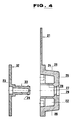
- FIG 4 showing in section the two components of the anchoring bracket shown in separated state and in section.
- the first part comprising a shoe 32 with the sole 23, which is flat with a circular contour.
- the sole 23 merges into an axial mounting stud 33 with an annular arrester rim 34 at the top.
- the figure shows how the arrester rim 34 is formed with an inclined upper surface and with a holding surface below in order that it may easily be introduced into a bushing to be latched and retained therein.
- This part may advantageously be manufactured by molding, e.g. of an extrudable rubber material.
- the second part of the anchoring bracket comprising an essentially flat piece 21 with a thickened region 24, a plateau region 25 parallel to the flat piece 21 with side ribs 26 (only two of the side ribs are visible in figure 4) and with a central bushing 28 with an opening 27 with an arrester lip.
- This component of the anchoring bracket may be manufactured my molding of plastic, e.g. polyurethane, and these parts are obviously matched so that, by introducing the mounting stud 33 into the bushing 28, the shoe may be attached to and latched into permanent engagement between the anchoring bracket arrester lip 29 and the mounting stud 33 arrester lip 34. This provides a mount enabling the sole to pivot around the mounting stud 33 axis.
- the anchoring bracket flat piece can be made of relatively hard and smooth plastic capable of providing solid and rigid anchoring eyelets, while the sole may be manufactured of a softer plastic and possibly a plastic with a higher coefficient of friction capable of providing a good frictional engagement with the caravan side wall.
- the possibility of pivoting the shoe relative to the remaining part of the mounting bracket provides some flexibility in use as the anchoring bracket trapezoid part may pivot slightly about the axis of the bushing 28 without loosening or moving of the frictional engagement.
Claims (13)
- Verfahren zur Befestigung eines Verankerungsarmes (20) an einem Grenzbereich eines Zeltleinwandstückes (10), wobei der Grenzbereich des Zeltleinwandstückes durch Zurückfalten eines Teiles der Leinwand auf den nicht gefalteten Teil derselben und durch Befestigen dieses Teiles am nichtgefalteten Teil geformt wird, um eine Umhüllung entlang dem Rand der Zeltleinwand zu bilden, und wobei der Verankerungsarm (20) mindestens eine Verankerungsöse (25,26) und eine Kontaktfläche (23) benachbart zur Öse umfaßt, der Verankerungsarm (20) so befestigt wird, daß sich die Kontaktfläche (23) von der Ebene der Zeltleinwand wegerstreckt, der Verankerungsarm über eine Befestigung durch beide gefaltete und miteinander verbundene Leinwandschichten zur Ausbildung der Umhüllung innerhalb einer engen, im wesentlichen linearen Zone (18) montiert wird und der Befestigungsarm (20) so angeordnet wird, daß sich die Befestigungszone (18) im wesentlichen parallel zur Umhüllung erstreckt.
- Verankerungsarm (20) zur Befestigung an einem Stück Zeltleinwand benachbart zu einem Grenzbereich des Zeltleinwandstückes (10) entlang einer Zone, die sich im wesentlichen parallel zum Grenzbereich erstreckt, mit mindestens einer Verankerungsöse (25,26), einer Kontaktfläche (23), die einen Abschnitt des Verankerungsarmes (20) benachbart zur Verankerungsöse (25,26) gegen eine planare Fläche lagern kann, und einer Befestigungszone (18), die an dem Zeltleinwandstück (10) befestigt werden kann, wobei der Verankerungsarm (20) ein im wesentlichen flaches Stück (21) aus flexiblem Material umfaßt, das eine breite Basislinie benachbart zur Befestigungszone und Seitenränder aufweist, die in der Richtung zur Verankerungsöse (25,26) hin konvergieren, so daß sie sich in einem Bereich benachbart zur beabsichtigten Befestigungszone (18) befinden und sich hiervon mindestens teilweise in der Richtung zur Verankerungsöse (25,26) hin erstrecken, und zwar entlang den Seitenrändern flexibler als im mittleren Bereich zwischen den Seitenrändern, so daß jedwede auf die Verankerungsöse aufgebrachte Kraft im befestigten Zustand auf die Leinwand an der Befestigungszone mit einer reduzierten Neigung zur Konzentration der Kraft an den Enden der Befestigungszone übertragen wird.
- Verankerungsarm (20) nach Anspruch 2, dadurch gekennzeichnet, daß die Kontaktfläche (23) einen weichen, nachgiebigen Überzug aufweist, der als Kontaktfläche dienen kann.
- Verankerungsarm (20) nach Anspruch 3, dadurch gekennzeichnet, daß die Verankerungsöse (25,26) aus der Ebene des flachen Stückes (21) des Verankerungsarmes vorsteht.
- Verankerungsarm (20) nach Anspruch 3 oder 4, dadurch gekennzeichnet, daß das den Überzug umfassende Material einen höheren Reibungskoeffizienten besitzt als das flache Stück (21).
- Verankerungsarm (20) nach einem der Ansprüche 2-5, dadurch gekennzeichnet, daß die Verankerungsöse (25,26) mindestens zwei Ösen mit unterschiedlichen Orientierungen umfaßt.
- Verankerungsarm (20) nach Anspruch 6, dadurch gekennzeichnet, daß die Verankerungsöse (25,26) vier Ösen aufweist, die entlang zwei Achsen parallel zur Ebene der Kontaktsohlenfläche (23) und senkrecht zueinander orientiert sind.
- Verankerungsarm (20) nach einem der Ansprüche 2-7, dadurch gekennzeichnet, daß er ein erstes und zweites Teil aufweist, wobei das erste Teil an der Leinwand (10) befestigt ist, das zweite Teil die Kontaktfläche (23) umfaßt, das erste Teil eine Fassung (28) aufweist und das zweite Teil einen Bolzen (33) besitzt, der derart in der Fassung (28) aufgenommen und gehaltert ist, daß das zweite Teil relativ zum ersten Teil verschwenkbar ist.
- Verankerungsarm (20) nach Anspruch 8, dadurch gekennzeichnet, daß das zweite Teil relativ zum ersten Teil um eine Schwenkachse verschwenkbar ist, die sich allgemein senkrecht zur Kontaktfläche (23) erstreckt.
- Zeltbahn zur lösbaren Befestigung an einem Caravan (1) oder einem entsprechenden Fahrzeug, der bzw. das eine Außenwandfläche und ein Hohlprofil (2) mit einem Längsschlitz umfaßt, welches sich entlang mindestens einem Abschnitt der Außenwandfläche erstreckt, mit einer Leinwand (10) und einem Wulst (11,12,13) entlang einem Rand der Leinwand, der in das Hohlprofil (2) einsetzbar ist, wobei sich die Leinwand durch den Längsschlitz und vom Wulst weg erstreckt, um die Zeltbahn lösbar am Caravan (1) zu befestigen, wobei die Leinwand (10), wenn sie in einer allgemein vom Wulstrand, der im Hohlprofil gehalten wird, wegweisenden Richtung gespannt ist, so aufgehangen werden kann, daß sie sich allgemein von der Caravanwandfläche weg und in Spannrichtung erstreckt, und wobei die Zeltbahn mindestens einen Verankerungsarm (20) umfaßt, der mindestens eine Verankerungsöse (25,26) und eine Kontaktfläche (23) aufweist, die den Abschnitt benachbart zur Verankerungsöse gegen die Außenwandfläche des Karavans abstützen kann, und wobei der Verankerungsarm (20) so an der Leinwand (10) der Zeltbahn befestigt ist, daß sich die Kontaktfläche (23) aus der Ebene des benachbarten Abschnittes der gespannten Leinwand der Zeltbahn heraus erstreckt.
- Zeltbahn nach Anspruch 10, dadurch gekennzeichnet, daß der Wulst durch Zurückfalten und Zusammennähen eines Gewebebandes (11), das an einem Randabschnitt der Leinwand (10) der Zeltbahn befestigt ist, geformt ist, um eine Umhüllung zu bilden, die einen Längskörper (12) enthält, welcher einen Kern des Wulstes bildet, und daß der Verankerungsarm (20) durch Befestigung durch beide, die Umhüllung bildende Wandschichten innerhalb einer engen, im wesentlichen linearen Zone (18) montiert ist, wobei sich diese Zone im wesentlichen parallel zum Wulst erstreckt.
- Zeltbahn nach Anspruch 10 oder 11, dadurch gekennzeichnet, daß der Verankerungsarm (20) ein im wesentlichen flaches und längliches Stück (21) aus flexiblem Material umfaßt, so daß sich ein Abschnitt des Armes benachbart zur Befestigungszone (18) im wesentlichen parallel zur Ebene des benachbarten Abschnittes der gespannten Zeltbahnleinwand (10) erstrecken kann, während sich ein anderer Abschnitt des Armes benachbart zur Verankerungsöse durchbiegen und sich im wesentlichen senkrecht zur Ebene erstrecken kann.
- Zeltbahn nach einem der Ansprüche 10,11 oder 12, dadurch gekennzeichnet, daß sie mindestens einen Verankerungsarm (20) nach einem der Ansprüche 2-9 umfaßt.
Applications Claiming Priority (2)
| Application Number | Priority Date | Filing Date | Title |
|---|---|---|---|
| DK430489A DK162904C (da) | 1989-08-31 | 1989-08-31 | Fremgangsmåde til påsætning af en indretning på et telt, indretning til påsætning på et telt og telt |
| DK4304/89 | 1989-08-31 |
Publications (2)
| Publication Number | Publication Date |
|---|---|
| EP0415233A1 EP0415233A1 (de) | 1991-03-06 |
| EP0415233B1 true EP0415233B1 (de) | 1995-05-24 |
Family
ID=8132260
Family Applications (1)
| Application Number | Title | Priority Date | Filing Date |
|---|---|---|---|
| EP90115985A Expired - Lifetime EP0415233B1 (de) | 1989-08-31 | 1990-08-21 | Verfahren zum Festmachen einer Vorrichtung an einem Zelt, Vorrichtung zum Festmachen an einem Zelt und Zelt |
Country Status (5)
| Country | Link |
|---|---|
| US (1) | US5190066A (de) |
| EP (1) | EP0415233B1 (de) |
| DE (1) | DE69019636D1 (de) |
| DK (1) | DK162904C (de) |
| PT (1) | PT95145A (de) |
Families Citing this family (13)
| Publication number | Priority date | Publication date | Assignee | Title |
|---|---|---|---|---|
| FR2751360B1 (fr) * | 1996-07-19 | 1998-10-09 | Trigano Sa | Dispositif de fixation d'auvent ou similaire |
| ES2251062T3 (es) | 1997-03-12 | 2006-04-16 | Juan Moreno Jumilla | Disposicion para union de telas a miembros estructurales de soporte y parasol realizado conforme a la misma. |
| GB2339732A (en) * | 1998-07-18 | 2000-02-09 | John Ernest Cook | Supporting awnings on vehicles |
| NL1021062C2 (nl) * | 2002-07-12 | 2004-01-13 | Egbert Berend Holtkamp | Voortentconstructie en kampeerverblijf voorzien van een voortentconstructie. |
| ES2237246B1 (es) * | 2002-11-15 | 2006-10-01 | Jose Manuel Saez Rodriguez | Sistema de montaje de las piezas cobertoras en avances de caravana, modulos de cocina y similares. |
| SE524996C2 (sv) * | 2003-03-11 | 2004-11-09 | Teodor Oprean | Dockningsanordning för en husvagn till ett förtält |
| US20070120396A1 (en) * | 2005-11-28 | 2007-05-31 | Rheinheimer Michael T | Tent attachment for a recreational vehicle |
| US8434272B2 (en) * | 2010-01-29 | 2013-05-07 | Edward F. MARTINEZ | Weatherproofing assembly for use with a slide-out compartment of recreational vehicle |
| EP2716840B1 (de) * | 2012-10-08 | 2016-05-18 | Thule Sweden AB | Anordnung eines Zeltes und einer Markise |
| US10077574B1 (en) | 2015-09-02 | 2018-09-18 | Tepui Outdoors, Inc. | Hard shell rooftop tent with utility rails |
| US9995055B1 (en) | 2015-09-02 | 2018-06-12 | Tepui Outdoors, Inc. | Adaptable tent system with interconnecting member |
| US10208502B2 (en) | 2016-09-01 | 2019-02-19 | Tepui Outdoors, Inc. | Inflatable rooftop tent system for vehicles |
| EP4010549A1 (de) * | 2019-11-07 | 2022-06-15 | Bent GmbH | Adapterelement und baukastensystem |
Family Cites Families (12)
| Publication number | Priority date | Publication date | Assignee | Title |
|---|---|---|---|---|
| US2808065A (en) * | 1954-06-11 | 1957-10-01 | Edwin E Ellis | Awning support |
| GB926369A (en) * | 1960-10-06 | 1963-05-15 | Robert Georges Andrault | Awnings, particularly for caravans |
| FR80726E (fr) * | 1961-11-27 | 1963-06-07 | Fixation amovible d'auvent ou de store à un véhicule, en particulier aux caravanes | |
| FR1363930A (fr) * | 1963-03-14 | 1964-06-19 | Anciens Etablissements E Faver | Perfectionnements au montage d'un auvent sur une caravane ou véhicule similaire |
| US3612145A (en) * | 1970-01-09 | 1971-10-12 | Astrup Co | Rollup awning |
| US3720438A (en) * | 1971-04-16 | 1973-03-13 | E Johnson | Awning fixture |
| DE2309270A1 (de) * | 1973-02-24 | 1974-08-29 | Fendt & Co Xaver | Vorzelt fuer einen wohnwagen |
| FR2246416A1 (en) * | 1973-10-03 | 1975-05-02 | Pollux Sarl | Support pillar for caravan extension canopy - telescopic tube traps canopy edge in gutter and hooks under bodywork |
| DE2551917C3 (de) * | 1975-11-19 | 1978-05-18 | Guenther 7830 Emmendingen Bergerhoff | Starres Vorzeltdach für Wohnwagen |
| FR2516767A1 (fr) * | 1981-11-20 | 1983-05-27 | Bores Simon | Auvent pour caravane, adaptable sur des caravanes de longueurs differentes |
| US4634172A (en) * | 1985-11-29 | 1987-01-06 | Duda Henry J | Flexible hinge rain sealing mechanism |
| DK154711C (da) * | 1986-08-06 | 1989-06-12 | Campion Production Aps | Beslag til teltstang samt anvendelse heraf |
-
1989
- 1989-08-31 DK DK430489A patent/DK162904C/da not_active IP Right Cessation
-
1990
- 1990-08-21 EP EP90115985A patent/EP0415233B1/de not_active Expired - Lifetime
- 1990-08-21 DE DE69019636T patent/DE69019636D1/de not_active Expired - Lifetime
- 1990-08-28 US US07/573,974 patent/US5190066A/en not_active Expired - Fee Related
- 1990-08-30 PT PT95145A patent/PT95145A/pt not_active Application Discontinuation
Also Published As
| Publication number | Publication date |
|---|---|
| EP0415233A1 (de) | 1991-03-06 |
| US5190066A (en) | 1993-03-02 |
| DK430489A (da) | 1991-03-01 |
| DK162904B (da) | 1991-12-23 |
| DK430489D0 (da) | 1989-08-31 |
| DE69019636D1 (de) | 1995-06-29 |
| PT95145A (pt) | 1992-04-30 |
| DK162904C (da) | 1995-03-13 |
Similar Documents
| Publication | Publication Date | Title |
|---|---|---|
| EP0415233B1 (de) | Verfahren zum Festmachen einer Vorrichtung an einem Zelt, Vorrichtung zum Festmachen an einem Zelt und Zelt | |
| US4013315A (en) | Rain curtain assembly for golf carts | |
| US6601904B2 (en) | Retractable awning with transition plate for a golf cart | |
| US5787956A (en) | Foldable car sunshade curtain | |
| US5396917A (en) | Self erecting high top tent | |
| US6226813B1 (en) | Anchoring system for a beach blanket | |
| WO1999014454A2 (en) | Inflatable tent | |
| US5459950A (en) | Collapsible snowshoe with a pivoting binding | |
| US6736264B2 (en) | Golf bag and frame for the same | |
| US5400813A (en) | Awning for recreational vehicles | |
| US5733000A (en) | Surf board support and carrier chair combination | |
| CA2277356A1 (en) | Golf ball cleaning device | |
| US20020139403A1 (en) | Automobile umbrella | |
| US6808463B1 (en) | Soccer goal assembly | |
| US6443405B1 (en) | Golf bag with seating apparatus | |
| WO2001007732A1 (en) | Tent pole clip | |
| US5265839A (en) | Umbrella support means for use with a golf caddy car | |
| US20070090265A1 (en) | Easel | |
| US20040123886A1 (en) | Beach umbrella with tie-down | |
| JP2001027498A (ja) | エアコン室内機洗浄用カバー | |
| JP2728860B2 (ja) | テント用庇構造 | |
| CN218606320U (zh) | 一种按摩沐浴球 | |
| US6851893B1 (en) | Portable mooring dock for a boat | |
| KR200359059Y1 (ko) | 텐트 폴 지지구조 | |
| US20100307695A1 (en) | Removable, hanging awning for indoor and low wind outdoor use |
Legal Events
| Date | Code | Title | Description |
|---|---|---|---|
| PUAI | Public reference made under article 153(3) epc to a published international application that has entered the european phase |
Free format text: ORIGINAL CODE: 0009012 |
|
| AK | Designated contracting states |
Kind code of ref document: A1 Designated state(s): BE DE ES FR GB GR IT NL SE |
|
| 17P | Request for examination filed |
Effective date: 19910715 |
|
| 17Q | First examination report despatched |
Effective date: 19920731 |
|
| GRAA | (expected) grant |
Free format text: ORIGINAL CODE: 0009210 |
|
| AK | Designated contracting states |
Kind code of ref document: B1 Designated state(s): BE DE ES FR GB GR IT NL SE |
|
| PG25 | Lapsed in a contracting state [announced via postgrant information from national office to epo] |
Ref country code: ES Free format text: THE PATENT HAS BEEN ANNULLED BY A DECISION OF A NATIONAL AUTHORITY Effective date: 19950524 Ref country code: BE Effective date: 19950524 Ref country code: GR Free format text: LAPSE BECAUSE OF FAILURE TO SUBMIT A TRANSLATION OF THE DESCRIPTION OR TO PAY THE FEE WITHIN THE PRESCRIBED TIME-LIMIT Effective date: 19950524 Ref country code: IT Free format text: LAPSE BECAUSE OF FAILURE TO SUBMIT A TRANSLATION OF THE DESCRIPTION OR TO PAY THE FEE WITHIN THE PRE;WARNING: LAPSES OF ITALIAN PATENTS WITH EFFECTIVE DATE BEFORE 2007 MAY HAVE OCCURRED AT ANY TIME BEFORE 2007. THE CORRECT EFFECTIVE DATE MAY BE DIFFERENT FROM THE ONE RECORDED.SCRIBED TIME-LIMIT Effective date: 19950524 |
|
| REF | Corresponds to: |
Ref document number: 69019636 Country of ref document: DE Date of ref document: 19950629 |
|
| PG25 | Lapsed in a contracting state [announced via postgrant information from national office to epo] |
Ref country code: SE Effective date: 19950824 |
|
| PG25 | Lapsed in a contracting state [announced via postgrant information from national office to epo] |
Ref country code: DE Effective date: 19950825 |
|
| ET | Fr: translation filed | ||
| RAP2 | Party data changed (patent owner data changed or rights of a patent transferred) |
Owner name: TRIO SPORT INTERNATIONAL A/S |
|
| NLT2 | Nl: modifications (of names), taken from the european patent patent bulletin |
Owner name: TRIO SPORT INTERNATIONAL A/S |
|
| NLS | Nl: assignments of ep-patents |
Owner name: TRIO SPORT INTERNATIONAL A/S |
|
| PLBE | No opposition filed within time limit |
Free format text: ORIGINAL CODE: 0009261 |
|
| STAA | Information on the status of an ep patent application or granted ep patent |
Free format text: STATUS: NO OPPOSITION FILED WITHIN TIME LIMIT |
|
| 26N | No opposition filed | ||
| PGFP | Annual fee paid to national office [announced via postgrant information from national office to epo] |
Ref country code: GB Payment date: 20010815 Year of fee payment: 12 |
|
| PGFP | Annual fee paid to national office [announced via postgrant information from national office to epo] |
Ref country code: FR Payment date: 20010816 Year of fee payment: 12 |
|
| PGFP | Annual fee paid to national office [announced via postgrant information from national office to epo] |
Ref country code: NL Payment date: 20010831 Year of fee payment: 12 |
|
| REG | Reference to a national code |
Ref country code: GB Ref legal event code: IF02 |
|
| PG25 | Lapsed in a contracting state [announced via postgrant information from national office to epo] |
Ref country code: GB Free format text: LAPSE BECAUSE OF NON-PAYMENT OF DUE FEES Effective date: 20020821 |
|
| PG25 | Lapsed in a contracting state [announced via postgrant information from national office to epo] |
Ref country code: NL Free format text: LAPSE BECAUSE OF NON-PAYMENT OF DUE FEES Effective date: 20030301 |
|
| GBPC | Gb: european patent ceased through non-payment of renewal fee |
Effective date: 20020821 |
|
| PG25 | Lapsed in a contracting state [announced via postgrant information from national office to epo] |
Ref country code: FR Free format text: LAPSE BECAUSE OF NON-PAYMENT OF DUE FEES Effective date: 20030430 |
|
| NLV4 | Nl: lapsed or anulled due to non-payment of the annual fee |
Effective date: 20030301 |
|
| REG | Reference to a national code |
Ref country code: FR Ref legal event code: ST |