EP0415098B1 - Disjoncteur à moyennne tension à autosoufflage - Google Patents
Disjoncteur à moyennne tension à autosoufflage Download PDFInfo
- Publication number
- EP0415098B1 EP0415098B1 EP90114568A EP90114568A EP0415098B1 EP 0415098 B1 EP0415098 B1 EP 0415098B1 EP 90114568 A EP90114568 A EP 90114568A EP 90114568 A EP90114568 A EP 90114568A EP 0415098 B1 EP0415098 B1 EP 0415098B1
- Authority
- EP
- European Patent Office
- Prior art keywords
- volume
- piston
- blast
- circuit
- semi
- Prior art date
- Legal status (The legal status is an assumption and is not a legal conclusion. Google has not performed a legal analysis and makes no representation as to the accuracy of the status listed.)
- Expired - Lifetime
Links
- 230000007423 decrease Effects 0.000 claims abstract description 4
- 238000007599 discharging Methods 0.000 claims 2
- 238000007664 blowing Methods 0.000 description 21
- 239000007789 gas Substances 0.000 description 19
- 229910018503 SF6 Inorganic materials 0.000 description 4
- SFZCNBIFKDRMGX-UHFFFAOYSA-N sulfur hexafluoride Chemical compound FS(F)(F)(F)(F)F SFZCNBIFKDRMGX-UHFFFAOYSA-N 0.000 description 4
- 229960000909 sulfur hexafluoride Drugs 0.000 description 4
- 238000010586 diagram Methods 0.000 description 3
- 238000006073 displacement reaction Methods 0.000 description 3
- 230000000694 effects Effects 0.000 description 3
- 238000000926 separation method Methods 0.000 description 3
- 238000010891 electric arc Methods 0.000 description 2
- 238000010438 heat treatment Methods 0.000 description 2
- 239000011810 insulating material Substances 0.000 description 2
- 239000000463 material Substances 0.000 description 2
- 240000008042 Zea mays Species 0.000 description 1
- 239000000956 alloy Substances 0.000 description 1
- 229910045601 alloy Inorganic materials 0.000 description 1
- 230000008033 biological extinction Effects 0.000 description 1
- 230000006835 compression Effects 0.000 description 1
- 238000007906 compression Methods 0.000 description 1
- 238000009413 insulation Methods 0.000 description 1
- 238000002955 isolation Methods 0.000 description 1
- 229910052751 metal Inorganic materials 0.000 description 1
- 239000002184 metal Substances 0.000 description 1
- 230000008929 regeneration Effects 0.000 description 1
- 238000011069 regeneration method Methods 0.000 description 1
- 230000000284 resting effect Effects 0.000 description 1
- WFKWXMTUELFFGS-UHFFFAOYSA-N tungsten Chemical compound [W] WFKWXMTUELFFGS-UHFFFAOYSA-N 0.000 description 1
- 229910052721 tungsten Inorganic materials 0.000 description 1
- 239000010937 tungsten Substances 0.000 description 1
Images


Classifications
-
- H—ELECTRICITY
- H01—ELECTRIC ELEMENTS
- H01H—ELECTRIC SWITCHES; RELAYS; SELECTORS; EMERGENCY PROTECTIVE DEVICES
- H01H33/00—High-tension or heavy-current switches with arc-extinguishing or arc-preventing means
- H01H33/70—Switches with separate means for directing, obtaining, or increasing flow of arc-extinguishing fluid
- H01H33/98—Switches with separate means for directing, obtaining, or increasing flow of arc-extinguishing fluid the flow of arc-extinguishing fluid being initiated by an auxiliary arc or a section of the arc, without any moving parts for producing or increasing the flow
Definitions
- the present invention relates to a medium-voltage circuit breaker in which the insulation is ensured by a gas with good dielectric properties, such as sulfur hexafluoride (SF6), this same gas ensuring by self-blowing the extinction of the arc which form the separation of the arcing contacts of the circuit breaker.
- a gas with good dielectric properties such as sulfur hexafluoride (SF6)
- thermal volume or blowing volume which contains the arcing contacts and which, when these contacts are separated, is heated by the arcing and therefore undergoes a pressure increase. At the first zero crossing of the current, the gas expands and blows the arc.
- the blowing volume remains constant; when the current reaches a given threshold, an additional volume is added; for medium intensity cutting currents, the blowing volume increases by displacement of the piston against the action of the spring. In such devices, the expansion gas is polluted by the arc, which affects good blowing efficiency.
- An object of the present invention is to produce a circuit breaker which does not have this drawback and which makes it possible to ensure, when an upper threshold of current to be cut is reached, gas circulation, so as to better regenerate the dielectric qualities of the gas, and allow blowing on each of the roots of the arc.
- circuit breaker as defined by claim 1, the preamble of which reflects the state of the art according to DE-A-3,727,802.
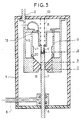
- FIG 1 there is a casing 1, made of insulating material, inside which there is a gas with good dielectric properties such as sulfur hexafluoride SF6, under a pressure of a few bars.
- a first socket 2 passing through the envelope in a sealed manner, is electrically connected, by means of a braid 3, to a first contact 4, called semi-fixed for reasons explained below.
- the contact 4 is terminated by a wearing part 4A made of a material resistant to the effects of the electric arc, for example a tungsten-based alloy.
- the rod 7 has an end 7A of material resistant to the effects of the electric arc.
- the semi-fixed contact 4 is fixed to a piston 8 sliding in a fixed cylinder 9 delimiting a first volume V1; the stroke of the piston 8 is limited upwards by a crown 9A and downwards by a shoulder 9B of the cylinder 9.
- the contact 4 is pushed by a spring 10 which is compressed when the circuit breaker is in the engaged position, as is the case in Figure 1.
- the cylinder 9 is placed inside a cylinder 12, of larger dimensions; V2 denotes the volume between the cylinders 9 and 12.
- the volumes V1 and V2 communicate through openings 13 made in the wall of cylinder 9, at the top of the latter.
- the cylinders 9 and 12 close at their lower part to define axial channels 14 passing through a blowing nozzle 15 through which the contact rod 7 slides.
- the travel limits of the end of the semi-fixed contact 4 are indicated by a and b, and by a and c the excursion limits of the movable contact 7.
- the circuit breaker works as follows.
- the movable contact 7 is driven by the operating device; contact 4, pushed by spring 10, moves with contact 7 to dimension b; during this phase, the volume V1 is compressed adiabatically; at the start of the movement, the piston 8 crosses the openings 13, so that there is no longer any communication between the volumes V1 and V2.
- contacts 4 and 7 separate and an arc springs; as soon as the end of the contact 7 has passed the neck of the nozzle 15 (dimension c), the gas of the volume V1 expands through the nozzle 15 and blows the arc.
- intensity currents for example between once the nominal current of the circuit and a given threshold value, for example five times the nominal current.
- the operation is similar, but, on separation of the contacts, the arc is of such intensity that the heating generates an overpressure which pushes the piston 8 against the action of the spring 10; however, as the current to be cut is only of medium intensity, this overpressure is insufficient to push the piston back beyond the openings 13, so that the volume V1 remains isolated.
- the overpressure in volume V1 is however sufficient to cut off the medium intensity currents.
- the arc which springs generates such an overpressure that it pushes the piston 8 beyond the area of the openings 13 and that communication is established between the volumes V1 and V2.
- the overpressure is limited to an acceptable value; when the current passes through zero, the gas pressurized in the volume V2 blows the arc through the channels 14 and through the openings 13 and the volume V1 if the piston 8 has remained beyond the area of these openings (FIG. 2) or through the volume V1 and the channels 14 if the piston 8 has passed through the area of the openings 13 (FIG. 3).
- FIG. 4 is a partial schematic view in axial section of a circuit breaker according to a second embodiment.
- the elements common to this figure and to the Figure 1 received the same reference numbers.
- This embodiment differs from that of FIGS. 1 to 3 in that the openings 13 are eliminated and replaced by valves 19, which can only open in the direction of the volume V1 towards the volume V2.
- These valves are calibrated to open only when the pressure in the volume V1 reaches a given threshold value, corresponding to an arc caused by the breaking of a high current. The operation is unchanged for breaking low and medium intensity currents.
- the pressure build-up in volume V1 causes the valves 19 to open and the volumes V1 and V2 to be put into communication. There is then a rise in pressure in the volume V2 and blowing of the arc by the blowing channels 14.
- Figure 5 is a schematic partial view in axial section of a circuit breaker according to an alternative embodiment.
- the elements common to this figure and to figure 1 have been given the same reference numbers.
- the communication between the volumes V1 and V2 is carried out through the openings 13, as in FIG. 1, but the channels 14 are eliminated and replaced by one or more one-way valves 20 allowing the passage of gas only from the volume V2 to volume V1.
- This alternative embodiment has the advantage of allowing circulation of the hot gases in the volume V2, since they enter through the openings 13 and exit through the valves 20; a better regeneration of the dielectric properties of the blowing gas is thus obtained.
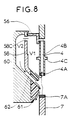
- FIG. 7 is a partial schematic view in axial section of another embodiment of the invention; here again, the elements common to this figure and to figure 1 have been given the same reference numbers.
- the casing 1 is closed at its upper part by a metal plate constituting the first socket 50.
- the semi-fixed contact 4 is extended outside the casing 1 and includes a 4D end suitable for receiving a spring 52 resting moreover on an insulating structure 53 surmounting the envelope 1.
- the electrical contact between the rod 4 and the plate 50 is produced by means of sliding contacts 54.
- the contact 4 comprises a flange 4C against which comes abut the piston 56 which, this time is no longer secured to the contact 4, but can slide along the contact.
- a spring 57 bears against the plate 50 and pushes the piston 56 against the flange 4C.
- the piston 56 slides in a cylinder 58, of volume V1, comprising inside a shoulder 58A to limit the stroke of the piston 56.
- the end of the cylinder opposite the piston is terminated by a conical portion 58B, made of insulating material, provided with an orifice for the passage of the movable contact 7.
- the cylinder 58 is provided in its part upper of a plurality of openings 58C communicating when the piston 56 is in the high position, the volume V1 with a volume V2 defined by a cylinder 60 coaxial with the cylinder 58 and fixed to the plate 50.
- the cylinder 60 is closed at its lower part by an insulating nozzle 61 defining, with the conical part 58B, a passage 62 opening onto the arc zone.
- the interior of the tube 4 communicates with the volume V3 surmounting the piston 56 by holes 64; this volume V3 communicates with the volume V4 outside the cylinder 60 by holes 65. All these holes promote the circulation of the gas inside the envelope 1.
Landscapes
- Circuit Breakers (AREA)
- Electrical Discharge Machining, Electrochemical Machining, And Combined Machining (AREA)
- Emergency Protection Circuit Devices (AREA)
- Gas-Insulated Switchgears (AREA)
- Organic Insulating Materials (AREA)
- Driving Mechanisms And Operating Circuits Of Arc-Extinguishing High-Tension Switches (AREA)
- Keying Circuit Devices (AREA)
- Electrophonic Musical Instruments (AREA)
- Push-Button Switches (AREA)
Applications Claiming Priority (2)
| Application Number | Priority Date | Filing Date | Title |
|---|---|---|---|
| FR8911018 | 1989-08-18 | ||
| FR8911018A FR2651065B1 (fr) | 1989-08-18 | 1989-08-18 | Disjoncteur a moyenne tension a autosoufflage |
Publications (2)
| Publication Number | Publication Date |
|---|---|
| EP0415098A1 EP0415098A1 (fr) | 1991-03-06 |
| EP0415098B1 true EP0415098B1 (fr) | 1995-03-01 |
Family
ID=9384796
Family Applications (1)
| Application Number | Title | Priority Date | Filing Date |
|---|---|---|---|
| EP90114568A Expired - Lifetime EP0415098B1 (fr) | 1989-08-18 | 1990-07-30 | Disjoncteur à moyennne tension à autosoufflage |
Country Status (11)
| Country | Link |
|---|---|
| US (1) | US5179257A (da) |
| EP (1) | EP0415098B1 (da) |
| JP (1) | JP2568304B2 (da) |
| CN (1) | CN1050287A (da) |
| AT (1) | ATE119313T1 (da) |
| BR (1) | BR9004060A (da) |
| CA (1) | CA2023525C (da) |
| DE (1) | DE69017310T2 (da) |
| DK (1) | DK0415098T3 (da) |
| ES (1) | ES2070221T3 (da) |
| FR (1) | FR2651065B1 (da) |
Families Citing this family (8)
| Publication number | Priority date | Publication date | Assignee | Title |
|---|---|---|---|---|
| FR2694127B1 (fr) * | 1992-07-24 | 1994-08-19 | Alsthom Gec | Disjoncteur à deux chambres de coupure concentriques. |
| RU94028648A (ru) * | 1993-08-10 | 1996-07-27 | Трик Холдингз Лимитед (BM) | Способ и устройство для технического обслуживания внутренней поверхности большого резервуара |
| JP5242461B2 (ja) * | 2009-03-06 | 2013-07-24 | 株式会社東芝 | ガス遮断器 |
| CN104335315B (zh) | 2012-05-22 | 2017-04-05 | 三菱电机株式会社 | 气体断路器 |
| KR101809385B1 (ko) * | 2013-07-19 | 2017-12-14 | 가부시키가이샤 히타치세이사쿠쇼 | 가스 차단기 |
| JP6435227B2 (ja) * | 2015-04-07 | 2018-12-05 | 株式会社日立製作所 | ガス遮断器 |
| US10984973B2 (en) * | 2017-07-31 | 2021-04-20 | General Electric Technology Gmbh | Electric switch provided with an arc-blasting unit |
| CN108970792A (zh) * | 2018-07-12 | 2018-12-11 | 姹や匠 | 一种碎纸机 |
Family Cites Families (8)
| Publication number | Priority date | Publication date | Assignee | Title |
|---|---|---|---|---|
| NL272063A (da) * | 1960-12-02 | |||
| JPS53117764A (en) * | 1977-03-24 | 1978-10-14 | Mitsubishi Electric Corp | Switch |
| CH649416A5 (de) * | 1980-01-25 | 1985-05-15 | Sprecher & Schuh Ag | Druckgasschalter. |
| US4327263A (en) * | 1980-06-17 | 1982-04-27 | Mitsubishi Denke Kabushiki Kaisha | Switching device |
| FR2520928A1 (fr) * | 1982-02-04 | 1983-08-05 | Alsthom Atlantique | Disjoncteur a auto-soufflage pneumatique |
| US4517425A (en) * | 1983-09-14 | 1985-05-14 | Mcgraw-Edison Company | Self-flow generating gas interrupter |
| DE3727802A1 (de) * | 1987-08-20 | 1989-03-02 | Licentia Gmbh | Selbstloeschender druckgasschalter |
| FR2622737B1 (fr) * | 1987-11-04 | 1995-04-14 | Merlin Gerin | Disjoncteur electrique a auto-expansion a volume de chambre d'extinction variable |
-
1989
- 1989-08-18 FR FR8911018A patent/FR2651065B1/fr not_active Expired - Fee Related
-
1990
- 1990-07-30 ES ES90114568T patent/ES2070221T3/es not_active Expired - Lifetime
- 1990-07-30 DE DE69017310T patent/DE69017310T2/de not_active Expired - Fee Related
- 1990-07-30 EP EP90114568A patent/EP0415098B1/fr not_active Expired - Lifetime
- 1990-07-30 DK DK90114568.0T patent/DK0415098T3/da active
- 1990-07-30 AT AT90114568T patent/ATE119313T1/de not_active IP Right Cessation
- 1990-08-16 JP JP2216452A patent/JP2568304B2/ja not_active Expired - Lifetime
- 1990-08-16 BR BR909004060A patent/BR9004060A/pt not_active IP Right Cessation
- 1990-08-17 US US07/569,056 patent/US5179257A/en not_active Expired - Fee Related
- 1990-08-17 CA CA002023525A patent/CA2023525C/fr not_active Expired - Fee Related
- 1990-08-18 CN CN90107927.8A patent/CN1050287A/zh active Pending
Also Published As
| Publication number | Publication date |
|---|---|
| ATE119313T1 (de) | 1995-03-15 |
| JPH0389423A (ja) | 1991-04-15 |
| DE69017310T2 (de) | 1995-06-29 |
| BR9004060A (pt) | 1991-09-03 |
| CA2023525C (fr) | 1996-12-31 |
| FR2651065A1 (fr) | 1991-02-22 |
| DK0415098T3 (da) | 1995-07-17 |
| CA2023525A1 (fr) | 1991-02-19 |
| CN1050287A (zh) | 1991-03-27 |
| US5179257A (en) | 1993-01-12 |
| ES2070221T3 (es) | 1995-06-01 |
| EP0415098A1 (fr) | 1991-03-06 |
| JP2568304B2 (ja) | 1997-01-08 |
| FR2651065B1 (fr) | 1996-07-05 |
| DE69017310D1 (de) | 1995-04-06 |
Similar Documents
| Publication | Publication Date | Title |
|---|---|---|
| FR2596575A1 (fr) | Disjoncteur a gaz dielectrique sous pression | |
| CA2035688C (fr) | Disjoncteur a moyenne ou haute tension a autosoufflage | |
| EP0415098B1 (fr) | Disjoncteur à moyennne tension à autosoufflage | |
| EP0591039B1 (fr) | Disjoncteur à haute tension à auto-soufflage ayant une chambre de coupure à compression de gaz réduite | |
| EP0302390B1 (fr) | Disjoncteur à haute ou moyenne tension à gaz sous pression à énergie de coupure prélevée sur celle de l'arc | |
| EP0239932B1 (fr) | Disjoncteur à haute tension à gaz diélectrique sous pression | |
| EP0380907B1 (fr) | Disjoncteur à haute et moyenne tension à gaz de soufflage | |
| FR2576144A1 (fr) | Disjoncteur a haute tension, a gaz comprime, a faible energie de manoeuvre | |
| EP0398211B1 (fr) | Disjoncteur à haute tension à gaz diélectrique de soufflage | |
| EP0759629B1 (fr) | Disjoncteur muni d'une résistance de fermeture avec dispositif d'insertion | |
| CA2017127C (fr) | Disjoncteur a moyenne tension a courant nominal eleve | |
| EP0458236B1 (fr) | Disjoncteur à moyenne tension | |
| EP0515268B1 (fr) | Dispositif d'insertion d'une varistance, incorporé dans un disjoncteur à haute tension | |
| EP0406794B1 (fr) | Disjoncteur à haute ou moyenne tension | |
| EP0456025B1 (fr) | Disjoncteur à haute tension à arc série | |
| FR2610763A1 (fr) | Disjoncteur a faible energie de manoeuvre | |
| EP0450567B1 (fr) | Disjoncteur à haute ou moyenne tension à contacts d'arc en bout | |
| EP0393458A1 (fr) | Disjoncteur à moyenne tension à gaz de soufflage | |
| FR2490397A2 (fr) | Disjoncteur a haute tension a arc tournant et autosoufflage | |
| FR2783088A1 (fr) | Interrupteur avec un systeme d'insertion d'une resistance a longue duree d'insertion | |
| EP0398116B1 (fr) | Disjoncteur à moyenne tension à autosoufflage | |
| FR2646961A1 (fr) | Disjoncteur a moyenne tension a autosoufflage | |
| EP0009446A1 (fr) | Disjoncteur à gaz pour circuits électriques sous haute tension | |
| FR2704685A1 (fr) | Disjoncteur à énergie de manÓoeuvre d'ouverture réduite. |
Legal Events
| Date | Code | Title | Description |
|---|---|---|---|
| PUAI | Public reference made under article 153(3) epc to a published international application that has entered the european phase |
Free format text: ORIGINAL CODE: 0009012 |
|
| AK | Designated contracting states |
Kind code of ref document: A1 Designated state(s): AT BE CH DE DK ES FR GB GR IT LI LU NL SE |
|
| 17P | Request for examination filed |
Effective date: 19910903 |
|
| 17Q | First examination report despatched |
Effective date: 19931102 |
|
| GRAA | (expected) grant |
Free format text: ORIGINAL CODE: 0009210 |
|
| AK | Designated contracting states |
Kind code of ref document: B1 Designated state(s): AT BE CH DE DK ES FR GB GR IT LI LU NL SE |
|
| REF | Corresponds to: |
Ref document number: 119313 Country of ref document: AT Date of ref document: 19950315 Kind code of ref document: T |
|
| REF | Corresponds to: |
Ref document number: 69017310 Country of ref document: DE Date of ref document: 19950406 |
|
| ITF | It: translation for a ep patent filed | ||
| GBT | Gb: translation of ep patent filed (gb section 77(6)(a)/1977) |
Effective date: 19950421 |
|
| REG | Reference to a national code |
Ref country code: ES Ref legal event code: FG2A Ref document number: 2070221 Country of ref document: ES Kind code of ref document: T3 |
|
| REG | Reference to a national code |
Ref country code: DK Ref legal event code: T3 |
|
| REG | Reference to a national code |
Ref country code: GR Ref legal event code: FG4A Free format text: 3016290 |
|
| PLBE | No opposition filed within time limit |
Free format text: ORIGINAL CODE: 0009261 |
|
| STAA | Information on the status of an ep patent application or granted ep patent |
Free format text: STATUS: NO OPPOSITION FILED WITHIN TIME LIMIT |
|
| 26N | No opposition filed | ||
| PGFP | Annual fee paid to national office [announced via postgrant information from national office to epo] |
Ref country code: GB Payment date: 19990614 Year of fee payment: 10 |
|
| PGFP | Annual fee paid to national office [announced via postgrant information from national office to epo] |
Ref country code: FR Payment date: 19990616 Year of fee payment: 10 |
|
| PGFP | Annual fee paid to national office [announced via postgrant information from national office to epo] |
Ref country code: CH Payment date: 19990617 Year of fee payment: 10 |
|
| PGFP | Annual fee paid to national office [announced via postgrant information from national office to epo] |
Ref country code: DK Payment date: 19990621 Year of fee payment: 10 |
|
| PGFP | Annual fee paid to national office [announced via postgrant information from national office to epo] |
Ref country code: SE Payment date: 19990622 Year of fee payment: 10 Ref country code: AT Payment date: 19990622 Year of fee payment: 10 |
|
| PGFP | Annual fee paid to national office [announced via postgrant information from national office to epo] |
Ref country code: NL Payment date: 19990624 Year of fee payment: 10 |
|
| PGFP | Annual fee paid to national office [announced via postgrant information from national office to epo] |
Ref country code: DE Payment date: 19990626 Year of fee payment: 10 |
|
| PGFP | Annual fee paid to national office [announced via postgrant information from national office to epo] |
Ref country code: LU Payment date: 19990629 Year of fee payment: 10 |
|
| PGFP | Annual fee paid to national office [announced via postgrant information from national office to epo] |
Ref country code: BE Payment date: 19990706 Year of fee payment: 10 |
|
| PGFP | Annual fee paid to national office [announced via postgrant information from national office to epo] |
Ref country code: ES Payment date: 19990719 Year of fee payment: 10 |
|
| PGFP | Annual fee paid to national office [announced via postgrant information from national office to epo] |
Ref country code: GR Payment date: 19990728 Year of fee payment: 10 |
|
| PG25 | Lapsed in a contracting state [announced via postgrant information from national office to epo] |
Ref country code: LU Free format text: LAPSE BECAUSE OF NON-PAYMENT OF DUE FEES Effective date: 20000730 Ref country code: GB Free format text: LAPSE BECAUSE OF NON-PAYMENT OF DUE FEES Effective date: 20000730 Ref country code: DK Free format text: LAPSE BECAUSE OF NON-PAYMENT OF DUE FEES Effective date: 20000730 Ref country code: AT Free format text: LAPSE BECAUSE OF NON-PAYMENT OF DUE FEES Effective date: 20000730 |
|
| PG25 | Lapsed in a contracting state [announced via postgrant information from national office to epo] |
Ref country code: SE Free format text: LAPSE BECAUSE OF NON-PAYMENT OF DUE FEES Effective date: 20000731 Ref country code: LI Free format text: LAPSE BECAUSE OF NON-PAYMENT OF DUE FEES Effective date: 20000731 Ref country code: GR Free format text: LAPSE BECAUSE OF NON-PAYMENT OF DUE FEES Effective date: 20000731 Ref country code: ES Free format text: LAPSE BECAUSE OF NON-PAYMENT OF DUE FEES Effective date: 20000731 Ref country code: CH Free format text: LAPSE BECAUSE OF NON-PAYMENT OF DUE FEES Effective date: 20000731 Ref country code: BE Free format text: LAPSE BECAUSE OF NON-PAYMENT OF DUE FEES Effective date: 20000731 |
|
| BERE | Be: lapsed |
Owner name: S.A. GEC ALSTHOM Effective date: 20000731 |
|
| PG25 | Lapsed in a contracting state [announced via postgrant information from national office to epo] |
Ref country code: NL Free format text: LAPSE BECAUSE OF NON-PAYMENT OF DUE FEES Effective date: 20010201 |
|
| REG | Reference to a national code |
Ref country code: CH Ref legal event code: PL |
|
| EUG | Se: european patent has lapsed |
Ref document number: 90114568.0 |
|
| GBPC | Gb: european patent ceased through non-payment of renewal fee |
Effective date: 20000730 |
|
| REG | Reference to a national code |
Ref country code: DK Ref legal event code: EBP |
|
| PG25 | Lapsed in a contracting state [announced via postgrant information from national office to epo] |
Ref country code: FR Free format text: LAPSE BECAUSE OF NON-PAYMENT OF DUE FEES Effective date: 20010330 |
|
| NLV4 | Nl: lapsed or anulled due to non-payment of the annual fee |
Effective date: 20010201 |
|
| REG | Reference to a national code |
Ref country code: FR Ref legal event code: ST |
|
| PG25 | Lapsed in a contracting state [announced via postgrant information from national office to epo] |
Ref country code: DE Free format text: LAPSE BECAUSE OF NON-PAYMENT OF DUE FEES Effective date: 20010501 |
|
| REG | Reference to a national code |
Ref country code: ES Ref legal event code: FD2A Effective date: 20010810 |
|
| PG25 | Lapsed in a contracting state [announced via postgrant information from national office to epo] |
Ref country code: IT Free format text: LAPSE BECAUSE OF NON-PAYMENT OF DUE FEES;WARNING: LAPSES OF ITALIAN PATENTS WITH EFFECTIVE DATE BEFORE 2007 MAY HAVE OCCURRED AT ANY TIME BEFORE 2007. THE CORRECT EFFECTIVE DATE MAY BE DIFFERENT FROM THE ONE RECORDED. Effective date: 20050730 |