EP0415098B1 - Self-blast circuit breaker for medium voltage - Google Patents
Self-blast circuit breaker for medium voltage Download PDFInfo
- Publication number
- EP0415098B1 EP0415098B1 EP90114568A EP90114568A EP0415098B1 EP 0415098 B1 EP0415098 B1 EP 0415098B1 EP 90114568 A EP90114568 A EP 90114568A EP 90114568 A EP90114568 A EP 90114568A EP 0415098 B1 EP0415098 B1 EP 0415098B1
- Authority
- EP
- European Patent Office
- Prior art keywords
- volume
- piston
- blast
- circuit
- semi
- Prior art date
- Legal status (The legal status is an assumption and is not a legal conclusion. Google has not performed a legal analysis and makes no representation as to the accuracy of the status listed.)
- Expired - Lifetime
Links
- 230000007423 decrease Effects 0.000 claims abstract description 4
- 238000007599 discharging Methods 0.000 claims 2
- 238000007664 blowing Methods 0.000 description 21
- 239000007789 gas Substances 0.000 description 19
- 229910018503 SF6 Inorganic materials 0.000 description 4
- SFZCNBIFKDRMGX-UHFFFAOYSA-N sulfur hexafluoride Chemical compound FS(F)(F)(F)(F)F SFZCNBIFKDRMGX-UHFFFAOYSA-N 0.000 description 4
- 229960000909 sulfur hexafluoride Drugs 0.000 description 4
- 238000010586 diagram Methods 0.000 description 3
- 238000006073 displacement reaction Methods 0.000 description 3
- 230000000694 effects Effects 0.000 description 3
- 238000000926 separation method Methods 0.000 description 3
- 238000010891 electric arc Methods 0.000 description 2
- 238000010438 heat treatment Methods 0.000 description 2
- 239000011810 insulating material Substances 0.000 description 2
- 239000000463 material Substances 0.000 description 2
- 240000008042 Zea mays Species 0.000 description 1
- 239000000956 alloy Substances 0.000 description 1
- 229910045601 alloy Inorganic materials 0.000 description 1
- 230000008033 biological extinction Effects 0.000 description 1
- 230000006835 compression Effects 0.000 description 1
- 238000007906 compression Methods 0.000 description 1
- 238000009413 insulation Methods 0.000 description 1
- 238000002955 isolation Methods 0.000 description 1
- 229910052751 metal Inorganic materials 0.000 description 1
- 239000002184 metal Substances 0.000 description 1
- 230000008929 regeneration Effects 0.000 description 1
- 238000011069 regeneration method Methods 0.000 description 1
- 230000000284 resting effect Effects 0.000 description 1
- WFKWXMTUELFFGS-UHFFFAOYSA-N tungsten Chemical compound [W] WFKWXMTUELFFGS-UHFFFAOYSA-N 0.000 description 1
- 229910052721 tungsten Inorganic materials 0.000 description 1
- 239000010937 tungsten Substances 0.000 description 1
Images


Classifications
-
- H—ELECTRICITY
- H01—ELECTRIC ELEMENTS
- H01H—ELECTRIC SWITCHES; RELAYS; SELECTORS; EMERGENCY PROTECTIVE DEVICES
- H01H33/00—High-tension or heavy-current switches with arc-extinguishing or arc-preventing means
- H01H33/70—Switches with separate means for directing, obtaining, or increasing flow of arc-extinguishing fluid
- H01H33/98—Switches with separate means for directing, obtaining, or increasing flow of arc-extinguishing fluid the flow of arc-extinguishing fluid being initiated by an auxiliary arc or a section of the arc, without any moving parts for producing or increasing the flow
Definitions
- the present invention relates to a medium-voltage circuit breaker in which the insulation is ensured by a gas with good dielectric properties, such as sulfur hexafluoride (SF6), this same gas ensuring by self-blowing the extinction of the arc which form the separation of the arcing contacts of the circuit breaker.
- a gas with good dielectric properties such as sulfur hexafluoride (SF6)
- thermal volume or blowing volume which contains the arcing contacts and which, when these contacts are separated, is heated by the arcing and therefore undergoes a pressure increase. At the first zero crossing of the current, the gas expands and blows the arc.
- the blowing volume remains constant; when the current reaches a given threshold, an additional volume is added; for medium intensity cutting currents, the blowing volume increases by displacement of the piston against the action of the spring. In such devices, the expansion gas is polluted by the arc, which affects good blowing efficiency.
- An object of the present invention is to produce a circuit breaker which does not have this drawback and which makes it possible to ensure, when an upper threshold of current to be cut is reached, gas circulation, so as to better regenerate the dielectric qualities of the gas, and allow blowing on each of the roots of the arc.
- circuit breaker as defined by claim 1, the preamble of which reflects the state of the art according to DE-A-3,727,802.
- FIG 1 there is a casing 1, made of insulating material, inside which there is a gas with good dielectric properties such as sulfur hexafluoride SF6, under a pressure of a few bars.
- a first socket 2 passing through the envelope in a sealed manner, is electrically connected, by means of a braid 3, to a first contact 4, called semi-fixed for reasons explained below.
- the contact 4 is terminated by a wearing part 4A made of a material resistant to the effects of the electric arc, for example a tungsten-based alloy.
- the rod 7 has an end 7A of material resistant to the effects of the electric arc.
- the semi-fixed contact 4 is fixed to a piston 8 sliding in a fixed cylinder 9 delimiting a first volume V1; the stroke of the piston 8 is limited upwards by a crown 9A and downwards by a shoulder 9B of the cylinder 9.
- the contact 4 is pushed by a spring 10 which is compressed when the circuit breaker is in the engaged position, as is the case in Figure 1.
- the cylinder 9 is placed inside a cylinder 12, of larger dimensions; V2 denotes the volume between the cylinders 9 and 12.
- the volumes V1 and V2 communicate through openings 13 made in the wall of cylinder 9, at the top of the latter.
- the cylinders 9 and 12 close at their lower part to define axial channels 14 passing through a blowing nozzle 15 through which the contact rod 7 slides.
- the travel limits of the end of the semi-fixed contact 4 are indicated by a and b, and by a and c the excursion limits of the movable contact 7.
- the circuit breaker works as follows.
- the movable contact 7 is driven by the operating device; contact 4, pushed by spring 10, moves with contact 7 to dimension b; during this phase, the volume V1 is compressed adiabatically; at the start of the movement, the piston 8 crosses the openings 13, so that there is no longer any communication between the volumes V1 and V2.
- contacts 4 and 7 separate and an arc springs; as soon as the end of the contact 7 has passed the neck of the nozzle 15 (dimension c), the gas of the volume V1 expands through the nozzle 15 and blows the arc.
- intensity currents for example between once the nominal current of the circuit and a given threshold value, for example five times the nominal current.
- the operation is similar, but, on separation of the contacts, the arc is of such intensity that the heating generates an overpressure which pushes the piston 8 against the action of the spring 10; however, as the current to be cut is only of medium intensity, this overpressure is insufficient to push the piston back beyond the openings 13, so that the volume V1 remains isolated.
- the overpressure in volume V1 is however sufficient to cut off the medium intensity currents.
- the arc which springs generates such an overpressure that it pushes the piston 8 beyond the area of the openings 13 and that communication is established between the volumes V1 and V2.
- the overpressure is limited to an acceptable value; when the current passes through zero, the gas pressurized in the volume V2 blows the arc through the channels 14 and through the openings 13 and the volume V1 if the piston 8 has remained beyond the area of these openings (FIG. 2) or through the volume V1 and the channels 14 if the piston 8 has passed through the area of the openings 13 (FIG. 3).
- FIG. 4 is a partial schematic view in axial section of a circuit breaker according to a second embodiment.
- the elements common to this figure and to the Figure 1 received the same reference numbers.
- This embodiment differs from that of FIGS. 1 to 3 in that the openings 13 are eliminated and replaced by valves 19, which can only open in the direction of the volume V1 towards the volume V2.
- These valves are calibrated to open only when the pressure in the volume V1 reaches a given threshold value, corresponding to an arc caused by the breaking of a high current. The operation is unchanged for breaking low and medium intensity currents.
- the pressure build-up in volume V1 causes the valves 19 to open and the volumes V1 and V2 to be put into communication. There is then a rise in pressure in the volume V2 and blowing of the arc by the blowing channels 14.
- Figure 5 is a schematic partial view in axial section of a circuit breaker according to an alternative embodiment.
- the elements common to this figure and to figure 1 have been given the same reference numbers.
- the communication between the volumes V1 and V2 is carried out through the openings 13, as in FIG. 1, but the channels 14 are eliminated and replaced by one or more one-way valves 20 allowing the passage of gas only from the volume V2 to volume V1.
- This alternative embodiment has the advantage of allowing circulation of the hot gases in the volume V2, since they enter through the openings 13 and exit through the valves 20; a better regeneration of the dielectric properties of the blowing gas is thus obtained.
- FIG. 7 is a partial schematic view in axial section of another embodiment of the invention; here again, the elements common to this figure and to figure 1 have been given the same reference numbers.
- the casing 1 is closed at its upper part by a metal plate constituting the first socket 50.
- the semi-fixed contact 4 is extended outside the casing 1 and includes a 4D end suitable for receiving a spring 52 resting moreover on an insulating structure 53 surmounting the envelope 1.
- the electrical contact between the rod 4 and the plate 50 is produced by means of sliding contacts 54.
- the contact 4 comprises a flange 4C against which comes abut the piston 56 which, this time is no longer secured to the contact 4, but can slide along the contact.
- a spring 57 bears against the plate 50 and pushes the piston 56 against the flange 4C.
- the piston 56 slides in a cylinder 58, of volume V1, comprising inside a shoulder 58A to limit the stroke of the piston 56.
- the end of the cylinder opposite the piston is terminated by a conical portion 58B, made of insulating material, provided with an orifice for the passage of the movable contact 7.
- the cylinder 58 is provided in its part upper of a plurality of openings 58C communicating when the piston 56 is in the high position, the volume V1 with a volume V2 defined by a cylinder 60 coaxial with the cylinder 58 and fixed to the plate 50.
- the cylinder 60 is closed at its lower part by an insulating nozzle 61 defining, with the conical part 58B, a passage 62 opening onto the arc zone.
- the interior of the tube 4 communicates with the volume V3 surmounting the piston 56 by holes 64; this volume V3 communicates with the volume V4 outside the cylinder 60 by holes 65. All these holes promote the circulation of the gas inside the envelope 1.
Landscapes
- Circuit Breakers (AREA)
- Electrical Discharge Machining, Electrochemical Machining, And Combined Machining (AREA)
- Emergency Protection Circuit Devices (AREA)
- Electrophonic Musical Instruments (AREA)
- Push-Button Switches (AREA)
- Keying Circuit Devices (AREA)
- Driving Mechanisms And Operating Circuits Of Arc-Extinguishing High-Tension Switches (AREA)
- Gas-Insulated Switchgears (AREA)
- Organic Insulating Materials (AREA)
Abstract
Description
La présente invention concerne un disjoncteur à moyenne tension dans lequel l'isolation est assurée par un gaz à bonnes propriétés diélectriques, tel que l'hexafluorure de soufre (SF6), ce même gaz assurant par autosoufflage l'extinction de l'arc qui se forme à la séparation des contacts d'arc du disjoncteur.The present invention relates to a medium-voltage circuit breaker in which the insulation is ensured by a gas with good dielectric properties, such as sulfur hexafluoride (SF6), this same gas ensuring by self-blowing the extinction of the arc which form the separation of the arcing contacts of the circuit breaker.
On trouve, dans ce type de disjoncteur, un volume appelé volume thermique ou volume de soufflage, qui contient les contacts d'arc et qui, au moment de la séparation de ces contacts, est échauffé par l'arc et subit de ce fait une augmentation de pression. Au premier passage par zéro du courant, le gaz se détend et vient souffler l'arc. Un tel disjoncteur, dont part le préambule de la revendication 1, est décrit dans le document DE-A-3 727 802.In this type of circuit breaker, there is a volume called thermal volume or blowing volume, which contains the arcing contacts and which, when these contacts are separated, is heated by the arcing and therefore undergoes a pressure increase. At the first zero crossing of the current, the gas expands and blows the arc. Such a circuit breaker, including the preamble of
On connaît les difficultés rencontrées pour réaliser un tel appareil:
- lors de la coupure des courants de faible intensité (par exemple de valeur inférieure ou égale à l'intensité nominale du courant dans le circuit dans lequel est inséré le disjoncteur), la montée en pression peut être insuffisante ou trop importante, selon la dimension du volume de soufflage. Si le volume de soufflage est important, la montée en pression est faible et le soufflage peut être insuffisant; si le volume de soufflage est faible, la montée en pression est importante, mais la durée de soufflage peut être insuffisante pour une bonne efficacité.
- lors de la coupure des courants de grande intensité (courants de court-circuit par exemple), la montée en pression ne doit pas être trop importante, ce qui pourrait entraîner des risques d'endommagement de la chambre de coupure.
- when cutting low intensity currents (for example of value less than or equal to the nominal current intensity in the circuit in which the circuit breaker is inserted), the pressure increase may be insufficient or too large, depending on the size of the blowing volume. If the blowing volume is large, the pressure build-up is low and the blowing may be insufficient; if the blowing volume is low, the pressure rise is significant, but the blowing time may be insufficient for good efficiency.
- when cutting large currents (short-circuit currents for example), the pressure build-up must not be too great, which could lead to risks of damage to the switching chamber.
Pour résoudre ces problèmes, il a été proposé, notamment par les documents DE - A -3 727 802 et EP - A - 0 315 505, de prévoir une chambre de coupure, servant de volume de soufflage, à volume variable selon l'intensité du courant à couper. Ceci est obtenu en remplaçant le contact fixe qu'on trouve habituellement dans les disjoncteur par un contact semi-fixe lié à un piston repoussé par un ressort antagoniste. Selon l'intensité du courant à couper, le déplacement du piston est plus ou moins important et corrélativement, le volume de soufflage est plus ou moins grand. Plus précisément, pour les faibles courants, le volume de soufflage reste constant; lorsque le courant atteint un seuil donné, un volume additionnel est ajouté; pour les courants à couper de moyenne intensité, le volume de soufflage augmente par déplacement du piston contre l'action du ressort. Dans de tels appareils, le gaz d'expansion est pollué par l'arc, ce qui nuit à une bonne efficacité du soufflage.To solve these problems, it has been proposed, in particular by documents DE - A -3 727 802 and EP - A - 0 315 505, to provide a cut-off chamber, serving as blowing volume, with variable volume according to the intensity of the current to be cut. This is achieved by replacing the fixed contact usually found in circuit breakers with a semi-fixed contact linked to a piston pushed back by an opposing spring. Depending on the intensity of the current to be cut, the displacement of the piston is more or less important and correlatively, the blowing volume is more or less large. More precisely, for low currents, the blowing volume remains constant; when the current reaches a given threshold, an additional volume is added; for medium intensity cutting currents, the blowing volume increases by displacement of the piston against the action of the spring. In such devices, the expansion gas is polluted by the arc, which affects good blowing efficiency.
Un but de la présente invention est de réaliser un disjoncteur ne présentant pas cet inconvénient et permettant d'assurer, lorsqu'un seuil supérieur de courant à couper est atteint, une circulation du gaz, de manière à mieux régénérer les qualités diélectriques du gaz, et de permettre un soufflage sur chacune des racines de l'arc.An object of the present invention is to produce a circuit breaker which does not have this drawback and which makes it possible to ensure, when an upper threshold of current to be cut is reached, gas circulation, so as to better regenerate the dielectric qualities of the gas, and allow blowing on each of the roots of the arc.
Ce but est atteint selon l'invention par le disjoncteur tel que défini par la revendication 1 dont le préambule reflète l'état de la technique selon DE-A- 3 727 802.This object is achieved according to the invention by the circuit breaker as defined by
En ce qui concerne des exemples de mise en oeuvre préférés de l'invention, référence est faite aux revendications secondaires.As regards preferred examples of implementation of the invention, reference is made to the secondary claims.
L'invention sera bien comprise par la description donnée ci-après de divers modes de réalisation de l'invention,en référence au dessin dans lequel:
- la figure 1 est une vue schématique partielle en coupe axiale d'un disjoncteur selon un premier mode de réalisation,
- les figures 2 et 3 sont des schémas expliquant le fonctionnement du disjoncteur de la figure 1 lors de la coupure des courants de forte intensité,
- la figure 4 est une vue schématique partielle en coupe axiale d'un disjoncteur selon un second mode de réalisation de l'invention,
- la figure 5 est une vue schématique partielle en coupe axiale d'un disjoncteur selon un troisième mode de réalisation de l'invention,
- la figure 6 est un schéma expliquant le fonctionnement du disjoncteur de la figure 5,
- la figure 7 est une vue schématique partielle en coupe axiale d'un disjoncteur selon un quatrième mode de réalisation de l'invention,
- la figure 8 est un schéma expliquant le fonctionnement du disjoncteur de la figure 7,
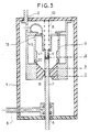
- FIG. 1 is a partial schematic view in axial section of a circuit breaker according to a first embodiment,
- FIGS. 2 and 3 are diagrams explaining the operation of the circuit breaker of FIG. 1 during the breaking of high currents,
- FIG. 4 is a partial schematic view in axial section of a circuit breaker according to a second embodiment of the invention,
- FIG. 5 is a partial schematic view in axial section of a circuit breaker according to a third embodiment of the invention,
- FIG. 6 is a diagram explaining the operation of the circuit breaker of FIG. 5,
- FIG. 7 is a partial schematic view in axial section of a circuit breaker according to a fourth embodiment of the invention,
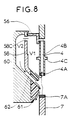
- FIG. 8 is a diagram explaining the operation of the circuit breaker of FIG. 7,
Dans la figure 1, on distingue une enveloppe 1, en matériau isolant, à l'intérieur de laquelle se trouve un gaz à bonnes propriétés diélectriques tel que l'hexafluorure de soufre SF6, sous une pression de quelques bars. Une première prise de courant 2, traversant l'enveloppe de manière étanche, est électriquement reliée, par l'intermédiaire d'une tresse 3, à un premier contact 4, appelé semi-fixe pour des raisons exposées plus loin. Le contact 4 est terminé par une pièce d'usure 4A en matériau résistant aux effets de l'arc électrique, par exemple un alliage à base de tungstène.In Figure 1, there is a
Une seconde prise de courant 5, traversant l'enveloppe 1 de manière étanche, est électriquement reliée par des contacts glissants 6, à une tige 7 constituant un contact mobile du disjoncteur; la tige 7 traverse l'enveloppe de manière étanche et est reliée à un mécanisme de manoeuvre non représenté. La tige 7 possède une extrémité 7A en matériau résistant aux effets de l'arc électrique.A
Le contact semi-fixe 4 est fixé à un piston 8 coulissant dans un cylindre fixe 9 délimitant un premier volume V1; la course du piston 8 est limitée vers le haut par une couronne 9A et vers le bas par un épaulement 9B du cylindre 9. Le contact 4 est poussé par un ressort 10 qui est comprimé lorsque le disjoncteur est en position enclenchée, comme c'est le cas dans la figure 1.The
Le cylindre 9 est placé à l'intérieur d'un cylindre 12, de dimensions plus grande; on désigne par V2 le volume compris entre les cylindres 9 et 12. Les volume V1 et V2 communiquent par des ouvertures 13 pratiquées dans la paroi du cylindre 9, à la partie haute de ce dernier. Les cylindres 9 et 12 se referment, à leur partie inférieure, pour définir des canaux axiaux 14 traversant une buse de soufflage 15 à travers laquelle coulisse la tige de contact 7.The
On a indiqué par a et b les limites de course de l'extrémité du contact semi-fixe 4, et par a et c les limites d'excursion du contact mobile 7.The travel limits of the end of the
Des trous tels que 16, pratiqués dans la prise 2, assurent une parfaite circulation des gaz à l'intérieur de l'enceinte 1.Holes such as 16, made in the
Le fonctionnement du disjoncteur est le suivant.The circuit breaker works as follows.
Il s'agit des courants dont l'intensité est inférieure ou égale à l'intensité nominale du circuit dans lequel est inséré le disjoncteur.These are currents whose intensity is less than or equal to the nominal current of the circuit in which the circuit breaker is inserted.
Le contact mobile 7 est entraîné par le dispositif de manoeuvre; le contact 4, poussé par le ressort 10,se déplace avec le contact 7 jusqu'à la cote b; pendant cette phase, le volume V1 est comprimé adiabatiquement; au début du mouvement, le piston 8 franchit les ouvertures 13, de sorte qu'il n'y a plus de communication entre les volumes V1 et V2. Lorsque l'extrémité du contact 4 atteint la cote b, les contacts 4 et 7 se séparent et un arc jaillit; dès que l'extrémité du contact 7 a dépassé le col de la buse 15 (cote c), le gaz du volume V1 se détend à travers la buse 15 et souffle l'arc. Dans cette opération, la surpression due à l'échauffement du gaz du volume V1 est faible, puisque le courant à couper est faible, et son action qui tend à repousser le piston 9 est contrebalancée par l'action du ressort 10. La faible énergie de soufflage nécessaire à la coupure d'un courant de faible intensité est fournie par la compression du gaz dans le volume V1 réduit au minimum.The
Il s'agit des courants d'intensité comprise par exemple entre une fois l'intensité nominale du circuit et une valeur de seuil donnée, par exemple cinq fois l'intensité nominale.These are the intensity currents for example between once the nominal current of the circuit and a given threshold value, for example five times the nominal current.
Le fonctionnement est analogue, mais, à la séparation des contacts, l'arc est d'une telle intensité que l'échauffement engendre une surpression qui repousse le piston 8 contre l'action du ressort 10; toutefois, comme le courant à couper n'est que d'intensité moyenne, cette surpression est insuffisante pour repousser le piston au-delà des ouvertures 13, de sorte que le volume V1 reste isolé. La surpression dans le volume V1 est cependant suffisante pour couper les courants de moyenne intensité.The operation is similar, but, on separation of the contacts, the arc is of such intensity that the heating generates an overpressure which pushes the
Il s'agit des courants dont l'intensité est supérieure à celle de la valeur de seuil précitée.These are currents whose intensity is greater than that of the aforementioned threshold value.
A la séparation des contacts, l'arc qui jaillit engendre une telle surpression qu'elle repousse le piston 8 au-delà de la zone des ouvertures 13 et qu'une communication s'établit entre les volumes V1 et V2. De la sorte, la surpression est limitée à valeur acceptable; au passage par zéro du courant,le gaz mis en pression dans le volume V2 souffle l'arc par les canaux 14 et par les ouvertures 13 et le volume V1 si le piston 8 est resté au-delà de la zone de ces ouvertures (figure 2) ou par le volume V1 et les canaux 14 si le piston 8 a repassé la zone des ouvertures 13 (figure 3).Upon separation of the contacts, the arc which springs generates such an overpressure that it pushes the
On note que grâce à la présence des canaux 14, le soufflage de l'arc, bien centré par la buse 15, est exercé très près de la racine de l'arc, ce qui est une garantie d'efficacité.It is noted that thanks to the presence of the
Il peut être avantageux de prévoir une ouverture axiale 4B du contact 4, ce qui permet d'exercer un soufflage encore près de l'autre racine de l'arc et dans le sens opposé à celui des autres jets de gaz.It may be advantageous to provide an axial opening 4B of the
La figure 4 est une vue schématique partielle en coupe axiale d'un disjoncteur selon un deuxième mode de réalisation. Les éléments communs à cette figure et à la figure 1 ont reçu les mêmes numéros de référence. Ce mode de réalisation diffère de celui des figures 1 à 3 en ce que les ouvertures 13 sont supprimées et remplacées par des clapets 19, qui ne peuvent s'ouvrir que dans le sens du volume V1 vers le volume V2. Ces clapets sont tarés pour ne s'ouvrir que lorsque la pression dans le volume V1 atteint une valeur de seuil donnée, correspondant à un arc occasionné par la coupure d'un courant de forte intensité. Le fonctionnement est inchangé pour la coupure des courants de faible et moyenne intensité. Pour la coupure des courants de forte intensité, la montée en pression dans le volume V1 provoque l'ouverture des clapets 19 et la mise en communication des volumes V1 et V2. Il y a alors montée en pression dans le volume V2 et soufflage de l'arc par les canaux de soufflage 14.Figure 4 is a partial schematic view in axial section of a circuit breaker according to a second embodiment. The elements common to this figure and to the Figure 1 received the same reference numbers. This embodiment differs from that of FIGS. 1 to 3 in that the
La figure 5 est une vue partielle schématique en coupe axiale d'un disjoncteur selon une variante de réalisation. Les éléments communs à cette figure et à la figure 1 ont reçu les mêmes numéros de référence.Figure 5 is a schematic partial view in axial section of a circuit breaker according to an alternative embodiment. The elements common to this figure and to figure 1 have been given the same reference numbers.
Dans cette variante, la communication entre les volumes V1 et V2 est réalisée par les ouvertures 13, comme dans la figure 1, mais les canaux 14 sont supprimés et remplacés par un ou plusieurs clapets unidirectionnels 20 n'autorisant le passage du gaz que du volume V2 vers le volume V1.In this variant, the communication between the volumes V1 and V2 is carried out through the
Le fonctionnement pour la coupure des courants faibles ou moyens est le même que précédemment.The operation for breaking low or medium currents is the same as before.
Le fonctionnement lors de la coupure des courants de forte intensité est le suivant:
- pendant la période où le courant est maximal, la montée en pression dans le volume V1 entraîne la remontée vers le haut du
contact 4 et dupiston 8 qui franchit les ouvertures 13, ce qui met en communication les volumes V1 et V2. La pression dans le volume V1 est alors supérieure à celle du volume V2. Les clapets 20 sont donc fermés. - lorsque le courant décroît vers zéro, - la coupure s'effectue au passage par zéro du courant-, la pression dans le volume V1 décroît ce qui peut provoquer le déplacement vers le bas du
piston 8 et l'isolement du volume V2 par rapport au volume V1. Lorsque la pression dans le volume V1 devient inférieure à celle du volume V2, les clapets 20 s'ouvrent et le gaz du volume V2 passe dans le volume V1 et contribue ainsi au soufflage de l'arc (figure 6).
- during the period when the current is maximum, the pressure increase in the volume V1 causes the upward movement of the
contact 4 and of thepiston 8 which crosses theopenings 13, which brings the volumes V1 and V2 into communication. The pressure in volume V1 is then higher than that in volume V2. Thevalves 20 are therefore closed. - when the current decreases towards zero, - the cut is made at the zero crossing of the current -, the pressure in the volume V1 decreases which can cause the displacement downwards of the
piston 8 and the isolation of the volume V2 with respect to the volume V1. When the pressure in volume V1 becomes lower than that in volume V2, thevalves 20 open and the gas in volume V2 passes into volume V1 and thus contributes to the blowing of the arc (FIG. 6).
Cette variante de réalisation présente l'avantage de permettre une circulation des gaz chauds dans le volume V2, puisqu'ils rentrent par les ouvertures 13 et sortent par les clapets 20; une meilleure régénération des propriétés diélectriques du gaz de soufflage est ainsi obtenue.This alternative embodiment has the advantage of allowing circulation of the hot gases in the volume V2, since they enter through the
La figure 7 est une vue schématique partielle en coupe axiale d'un autre mode de réalisation de l'invention; là encore, les éléments communs à cette figure et à la figure 1 ont reçu les mêmes numéros de référence.Figure 7 is a partial schematic view in axial section of another embodiment of the invention; here again, the elements common to this figure and to figure 1 have been given the same reference numbers.
Dans cette réalisation, l'enveloppe 1 est fermée à sa partie supérieure par un plateau métallique constituant la première prise de courant 50. Le contact semi-fixe 4 est prolongé à l'extérieur de l'enveloppe 1 et comprend une extrémité 4D apte à recevoir un ressort 52 s'appuyant par ailleurs sur une structure isolante 53 surmontant l'enveloppe 1. Le contact électrique entre la tige 4 et le plateau 50 est réalisé au moyen de contacts glissants 54. Le contact 4 comporte une collerette 4C contre laquelle vient buter le piston 56 qui, cette fois n'est plus solidaire du contact 4, mais peut coulisser le long du contact. Un ressort 57 s'appuie contre le plateau 50 et vient pousser le piston 56 contre la collerette 4C. Le piston 56 coulisse dans un cylindre 58, de volume V1, comprenant à son intérieur un épaulement 58A pour limiter la course du piston 56. L'extrémité du cylindre opposée au piston est terminée par une portion conique 58B, en matériau isolant, munie d'un orifice pour le passage du contact mobile 7. Le cylindre 58 est muni à sa partie supérieure d'une pluralité d'ouvertures 58C mettant en communication lorsque le piston 56 est en position haute, le volume V1 avec un volume V2 défini par un cylindre 60 coaxial au cylindre 58 et fixé au plateau 50. Le cylindre 60 est fermé à sa partie inférieure par une buse isolante 61 définissant, avec la partie conique 58B, un passage 62 s'ouvrant sur la zone d'arc.In this embodiment, the
L'intérieur du tube 4 communique avec le volume V3 surmontant le piston 56 par des perçages 64; ce volume V3 communique avec le volume V4 extérieur au cylindre 60 par des perçages 65. Tous ces perçages favorisent la circulation du gaz à l'intérieur de l'enveloppe 1.The interior of the
Le fonctionnement du disjoncteur, représenté en position enclenchée dans la figure 7, est analogue à celui décrit en référence à la figure 1, mais il existe une petite différence: lors de la coupure des courants de forte intensité, le piston remonte sous l'effet de la surpression dans le volume V1 jusqu'au-delà de la zone des ouvertures 58C, ce qui met en communication les volumes V1 et V2; mais, contrairement à ce qui se passait dans le dispositif de la figure 1, le contact 4, désolidarisé du piston, continue sa course sous l'action du ressort 52, de telle sorte que les gaz de soufflage agissent beaucoup plus près des racines de l'arc, comme le montre la figure 8.The operation of the circuit breaker, shown in the engaged position in Figure 7, is similar to that described with reference to Figure 1, but there is a small difference: when cutting high currents, the piston goes up under the effect from the overpressure in the volume V1 to beyond the area of the
Claims (7)
- Medium-voltage self-blast circuit-breaker comprising a sealed enclosure (1) filled with a dielectric gas and containing a semi-fixed first contact (4) electrically connected to a first terminal (2) and a mobile second contact (7) electrically connected to a second terminal (5) and mechanically coupled to an operating member, said semi-fixed contact being associated with a piston (8) moving in a first cylinder (9) constituting a first blast volume (V1) in which the tripping arc occurs and provided at one end with a blast nozzle (15) in which the mobile contact can be inserted when the circuit-breaker is in the engaged position, said piston being acted on by a spring (10) urging the piston in the direction in which said first volume decreases, means (13) being provided for causing the gas to circulate automatically between said first volume (V1) and a second volume (V2) when the high current to be interrupted reaches a predetermined threshold value, characterised in that said second volume (V2) is associated with means (14, 20, 62) for communication with the adjoining area of the blast nozzle (15) and in that said semi-fixed contact (4) is a tube communicating with a third volume (V3) consisting of the remainder of the enclosure.
- Circuit-breaker according to claim 1 characterised in that said means comprise a series of openings (13) in said first cylinder (9) discharging into said second blast volume (V2) and enabling effective circulation of said gas constituting the gas blast, said second volume (V2) communicating with the interior of the nozzle (15) via passages (14).
- Circuit-breaker according to claim 1 characterised in that said means comprise valves (19) disposed in the first cylinder (9) and discharging into the second volume (V2), said valves opening only in the direction from the first cylinder (9) towards the second volume (V2) and being calibrated to open only if the pressure in the first cylinder (9) reaches a predetermined threshold representing an arc caused by interrupting a high current, said second volume communicating via passages (14) with the interior of the blast nozzle (15).
- Circuit-breaker according to any one of claims 1 to 3 characterised in that said semi-fixed contact (4) is attached to the blast piston (8).
- Circuit-breaker according to any one of claims 1 to 3 characterised in that the semi-fixed contact (4) is separate from the piston (56).
- Circuit-breaker according to claim 1 characterised in that said communication means comprise passages (14) in the wall of said second volume and in the nozzle.
- Circuit-breaker according to claim 6 characterised in that said communication means comprise one-way valves (20) disposed between the first volume (V1) and the second volume (V2) in the vicinity of the nozzle (15).
Applications Claiming Priority (2)
| Application Number | Priority Date | Filing Date | Title |
|---|---|---|---|
| FR8911018A FR2651065B1 (en) | 1989-08-18 | 1989-08-18 | SELF-BLOWING MEDIUM VOLTAGE CIRCUIT BREAKER |
| FR8911018 | 1989-08-18 |
Publications (2)
| Publication Number | Publication Date |
|---|---|
| EP0415098A1 EP0415098A1 (en) | 1991-03-06 |
| EP0415098B1 true EP0415098B1 (en) | 1995-03-01 |
Family
ID=9384796
Family Applications (1)
| Application Number | Title | Priority Date | Filing Date |
|---|---|---|---|
| EP90114568A Expired - Lifetime EP0415098B1 (en) | 1989-08-18 | 1990-07-30 | Self-blast circuit breaker for medium voltage |
Country Status (11)
| Country | Link |
|---|---|
| US (1) | US5179257A (en) |
| EP (1) | EP0415098B1 (en) |
| JP (1) | JP2568304B2 (en) |
| CN (1) | CN1050287A (en) |
| AT (1) | ATE119313T1 (en) |
| BR (1) | BR9004060A (en) |
| CA (1) | CA2023525C (en) |
| DE (1) | DE69017310T2 (en) |
| DK (1) | DK0415098T3 (en) |
| ES (1) | ES2070221T3 (en) |
| FR (1) | FR2651065B1 (en) |
Families Citing this family (8)
| Publication number | Priority date | Publication date | Assignee | Title |
|---|---|---|---|---|
| FR2694127B1 (en) * | 1992-07-24 | 1994-08-19 | Alsthom Gec | Circuit breaker with two concentric breaking chambers. |
| NZ264205A (en) * | 1993-08-10 | 1996-07-26 | Tric Holdings Ltd | Servicing inside of large cylindrical vessel with small top opening: radial arms pivoted to central shaft so as to open outwardly after insertion in vessel |
| JP5242461B2 (en) * | 2009-03-06 | 2013-07-24 | 株式会社東芝 | Gas circuit breaker |
| US9384924B2 (en) | 2012-05-22 | 2016-07-05 | Mitsubishi Electric Corporation | Gas circuit breaker |
| WO2015008515A1 (en) * | 2013-07-19 | 2015-01-22 | 株式会社日立製作所 | Gas circuit breaker |
| JP6435227B2 (en) * | 2015-04-07 | 2018-12-05 | 株式会社日立製作所 | Gas circuit breaker |
| CN110914947B (en) * | 2017-07-31 | 2021-12-28 | 通用电器技术有限公司 | Electrical switch provided with an arc-blowing unit |
| CN108970792A (en) * | 2018-07-12 | 2018-12-11 | 姹や匠 | A kind of shredder |
Family Cites Families (8)
| Publication number | Priority date | Publication date | Assignee | Title |
|---|---|---|---|---|
| NL272063A (en) * | 1960-12-02 | |||
| JPS53117764A (en) * | 1977-03-24 | 1978-10-14 | Mitsubishi Electric Corp | Switch |
| CH649416A5 (en) * | 1980-01-25 | 1985-05-15 | Sprecher & Schuh Ag | EXHAUST GAS SWITCH. |
| US4327263A (en) * | 1980-06-17 | 1982-04-27 | Mitsubishi Denke Kabushiki Kaisha | Switching device |
| FR2520928A1 (en) * | 1982-02-04 | 1983-08-05 | Alsthom Atlantique | PNEUMATIC SELF-BLOWING CIRCUIT BREAKER |
| US4517425A (en) * | 1983-09-14 | 1985-05-14 | Mcgraw-Edison Company | Self-flow generating gas interrupter |
| DE3727802A1 (en) * | 1987-08-20 | 1989-03-02 | Licentia Gmbh | Self-extinguishing gas-blast circuit breaker |
| FR2622737B1 (en) * | 1987-11-04 | 1995-04-14 | Merlin Gerin | SELF-EXPANSIONAL ELECTRIC CIRCUIT BREAKER WITH VARIABLE EXTINCTION CHAMBER VOLUME |
-
1989
- 1989-08-18 FR FR8911018A patent/FR2651065B1/en not_active Expired - Fee Related
-
1990
- 1990-07-30 EP EP90114568A patent/EP0415098B1/en not_active Expired - Lifetime
- 1990-07-30 AT AT90114568T patent/ATE119313T1/en not_active IP Right Cessation
- 1990-07-30 ES ES90114568T patent/ES2070221T3/en not_active Expired - Lifetime
- 1990-07-30 DE DE69017310T patent/DE69017310T2/en not_active Expired - Fee Related
- 1990-07-30 DK DK90114568.0T patent/DK0415098T3/en active
- 1990-08-16 BR BR909004060A patent/BR9004060A/en not_active IP Right Cessation
- 1990-08-16 JP JP2216452A patent/JP2568304B2/en not_active Expired - Lifetime
- 1990-08-17 US US07/569,056 patent/US5179257A/en not_active Expired - Fee Related
- 1990-08-17 CA CA002023525A patent/CA2023525C/en not_active Expired - Fee Related
- 1990-08-18 CN CN90107927.8A patent/CN1050287A/en active Pending
Also Published As
| Publication number | Publication date |
|---|---|
| JPH0389423A (en) | 1991-04-15 |
| FR2651065B1 (en) | 1996-07-05 |
| CN1050287A (en) | 1991-03-27 |
| EP0415098A1 (en) | 1991-03-06 |
| ES2070221T3 (en) | 1995-06-01 |
| US5179257A (en) | 1993-01-12 |
| DE69017310T2 (en) | 1995-06-29 |
| DE69017310D1 (en) | 1995-04-06 |
| CA2023525C (en) | 1996-12-31 |
| ATE119313T1 (en) | 1995-03-15 |
| CA2023525A1 (en) | 1991-02-19 |
| FR2651065A1 (en) | 1991-02-22 |
| BR9004060A (en) | 1991-09-03 |
| JP2568304B2 (en) | 1997-01-08 |
| DK0415098T3 (en) | 1995-07-17 |
Similar Documents
| Publication | Publication Date | Title |
|---|---|---|
| FR2596575A1 (en) | PRESSURE DIELECTRIC GAS CIRCUIT BREAKER | |
| EP0415098B1 (en) | Self-blast circuit breaker for medium voltage | |
| EP0591039B1 (en) | H.T. self-blast circuit breaker having an arc chamber with reduced gas compression | |
| EP0302390B1 (en) | High or medium voltage gas blast circuit breaker with opening energy taken from the arc energy | |
| CA2035688C (en) | Self-extinguishing high or medium voltage circuit breaker | |
| EP0239932B1 (en) | High-tension gas blast circuit breaker | |
| EP0380907B2 (en) | High and medium voltage gas blast circuit breaker | |
| EP0398211B1 (en) | High tension gas blast circuit breaker | |
| EP0759629B1 (en) | Circuit breaker with closing resistor and insertion device | |
| CA2017127C (en) | High current rating medium voltage circuit-breaker | |
| EP0458236B1 (en) | Medium high voltage circuit breaker | |
| EP0406794B1 (en) | High or middle tension circuit breaker | |
| EP0456025B1 (en) | High voltage circuit interrupter with arc in series | |
| EP0450567B1 (en) | High- or medium voltage circuit breaker with abutting arcing contacts | |
| EP0515268B1 (en) | Varistor insertion device incorporated in an H.T. circuit breaker | |
| EP0393458A1 (en) | Blast gas medium voltage circuit breaker | |
| FR2490397A2 (en) | HV gas filled circuit breaker with semi-mobile arcing contact - uses arcing contact which moves down into arc chamber to divert arc current away from fixed contacts and form second series arc | |
| FR2783088A1 (en) | SWITCH WITH A LONG-TERM INSERTION RESISTOR INSERTION SYSTEM | |
| EP0398116B1 (en) | Medium high voltage self-blowing circuit breaker | |
| FR2646961A1 (en) | Self-blasting medium voltage circuit breaker. | |
| EP0009446A1 (en) | Compressed-gas high tension circuit interruptor | |
| FR2704685A1 (en) | Circuit breaker with reduced opening-operation energy |
Legal Events
| Date | Code | Title | Description |
|---|---|---|---|
| PUAI | Public reference made under article 153(3) epc to a published international application that has entered the european phase |
Free format text: ORIGINAL CODE: 0009012 |
|
| AK | Designated contracting states |
Kind code of ref document: A1 Designated state(s): AT BE CH DE DK ES FR GB GR IT LI LU NL SE |
|
| 17P | Request for examination filed |
Effective date: 19910903 |
|
| 17Q | First examination report despatched |
Effective date: 19931102 |
|
| GRAA | (expected) grant |
Free format text: ORIGINAL CODE: 0009210 |
|
| AK | Designated contracting states |
Kind code of ref document: B1 Designated state(s): AT BE CH DE DK ES FR GB GR IT LI LU NL SE |
|
| REF | Corresponds to: |
Ref document number: 119313 Country of ref document: AT Date of ref document: 19950315 Kind code of ref document: T |
|
| REF | Corresponds to: |
Ref document number: 69017310 Country of ref document: DE Date of ref document: 19950406 |
|
| ITF | It: translation for a ep patent filed | ||
| GBT | Gb: translation of ep patent filed (gb section 77(6)(a)/1977) |
Effective date: 19950421 |
|
| REG | Reference to a national code |
Ref country code: ES Ref legal event code: FG2A Ref document number: 2070221 Country of ref document: ES Kind code of ref document: T3 |
|
| REG | Reference to a national code |
Ref country code: DK Ref legal event code: T3 |
|
| REG | Reference to a national code |
Ref country code: GR Ref legal event code: FG4A Free format text: 3016290 |
|
| PLBE | No opposition filed within time limit |
Free format text: ORIGINAL CODE: 0009261 |
|
| STAA | Information on the status of an ep patent application or granted ep patent |
Free format text: STATUS: NO OPPOSITION FILED WITHIN TIME LIMIT |
|
| 26N | No opposition filed | ||
| PGFP | Annual fee paid to national office [announced via postgrant information from national office to epo] |
Ref country code: GB Payment date: 19990614 Year of fee payment: 10 |
|
| PGFP | Annual fee paid to national office [announced via postgrant information from national office to epo] |
Ref country code: FR Payment date: 19990616 Year of fee payment: 10 |
|
| PGFP | Annual fee paid to national office [announced via postgrant information from national office to epo] |
Ref country code: CH Payment date: 19990617 Year of fee payment: 10 |
|
| PGFP | Annual fee paid to national office [announced via postgrant information from national office to epo] |
Ref country code: DK Payment date: 19990621 Year of fee payment: 10 |
|
| PGFP | Annual fee paid to national office [announced via postgrant information from national office to epo] |
Ref country code: SE Payment date: 19990622 Year of fee payment: 10 Ref country code: AT Payment date: 19990622 Year of fee payment: 10 |
|
| PGFP | Annual fee paid to national office [announced via postgrant information from national office to epo] |
Ref country code: NL Payment date: 19990624 Year of fee payment: 10 |
|
| PGFP | Annual fee paid to national office [announced via postgrant information from national office to epo] |
Ref country code: DE Payment date: 19990626 Year of fee payment: 10 |
|
| PGFP | Annual fee paid to national office [announced via postgrant information from national office to epo] |
Ref country code: LU Payment date: 19990629 Year of fee payment: 10 |
|
| PGFP | Annual fee paid to national office [announced via postgrant information from national office to epo] |
Ref country code: BE Payment date: 19990706 Year of fee payment: 10 |
|
| PGFP | Annual fee paid to national office [announced via postgrant information from national office to epo] |
Ref country code: ES Payment date: 19990719 Year of fee payment: 10 |
|
| PGFP | Annual fee paid to national office [announced via postgrant information from national office to epo] |
Ref country code: GR Payment date: 19990728 Year of fee payment: 10 |
|
| PG25 | Lapsed in a contracting state [announced via postgrant information from national office to epo] |
Ref country code: LU Free format text: LAPSE BECAUSE OF NON-PAYMENT OF DUE FEES Effective date: 20000730 Ref country code: GB Free format text: LAPSE BECAUSE OF NON-PAYMENT OF DUE FEES Effective date: 20000730 Ref country code: DK Free format text: LAPSE BECAUSE OF NON-PAYMENT OF DUE FEES Effective date: 20000730 Ref country code: AT Free format text: LAPSE BECAUSE OF NON-PAYMENT OF DUE FEES Effective date: 20000730 |
|
| PG25 | Lapsed in a contracting state [announced via postgrant information from national office to epo] |
Ref country code: SE Free format text: LAPSE BECAUSE OF NON-PAYMENT OF DUE FEES Effective date: 20000731 Ref country code: LI Free format text: LAPSE BECAUSE OF NON-PAYMENT OF DUE FEES Effective date: 20000731 Ref country code: GR Free format text: LAPSE BECAUSE OF NON-PAYMENT OF DUE FEES Effective date: 20000731 Ref country code: ES Free format text: LAPSE BECAUSE OF NON-PAYMENT OF DUE FEES Effective date: 20000731 Ref country code: CH Free format text: LAPSE BECAUSE OF NON-PAYMENT OF DUE FEES Effective date: 20000731 Ref country code: BE Free format text: LAPSE BECAUSE OF NON-PAYMENT OF DUE FEES Effective date: 20000731 |
|
| BERE | Be: lapsed |
Owner name: S.A. GEC ALSTHOM Effective date: 20000731 |
|
| PG25 | Lapsed in a contracting state [announced via postgrant information from national office to epo] |
Ref country code: NL Free format text: LAPSE BECAUSE OF NON-PAYMENT OF DUE FEES Effective date: 20010201 |
|
| REG | Reference to a national code |
Ref country code: CH Ref legal event code: PL |
|
| EUG | Se: european patent has lapsed |
Ref document number: 90114568.0 |
|
| GBPC | Gb: european patent ceased through non-payment of renewal fee |
Effective date: 20000730 |
|
| REG | Reference to a national code |
Ref country code: DK Ref legal event code: EBP |
|
| PG25 | Lapsed in a contracting state [announced via postgrant information from national office to epo] |
Ref country code: FR Free format text: LAPSE BECAUSE OF NON-PAYMENT OF DUE FEES Effective date: 20010330 |
|
| NLV4 | Nl: lapsed or anulled due to non-payment of the annual fee |
Effective date: 20010201 |
|
| REG | Reference to a national code |
Ref country code: FR Ref legal event code: ST |
|
| PG25 | Lapsed in a contracting state [announced via postgrant information from national office to epo] |
Ref country code: DE Free format text: LAPSE BECAUSE OF NON-PAYMENT OF DUE FEES Effective date: 20010501 |
|
| REG | Reference to a national code |
Ref country code: ES Ref legal event code: FD2A Effective date: 20010810 |
|
| PG25 | Lapsed in a contracting state [announced via postgrant information from national office to epo] |
Ref country code: IT Free format text: LAPSE BECAUSE OF NON-PAYMENT OF DUE FEES;WARNING: LAPSES OF ITALIAN PATENTS WITH EFFECTIVE DATE BEFORE 2007 MAY HAVE OCCURRED AT ANY TIME BEFORE 2007. THE CORRECT EFFECTIVE DATE MAY BE DIFFERENT FROM THE ONE RECORDED. Effective date: 20050730 |