EP0456025B1 - High voltage circuit interrupter with arc in series - Google Patents
High voltage circuit interrupter with arc in series Download PDFInfo
- Publication number
- EP0456025B1 EP0456025B1 EP91106454A EP91106454A EP0456025B1 EP 0456025 B1 EP0456025 B1 EP 0456025B1 EP 91106454 A EP91106454 A EP 91106454A EP 91106454 A EP91106454 A EP 91106454A EP 0456025 B1 EP0456025 B1 EP 0456025B1
- Authority
- EP
- European Patent Office
- Prior art keywords
- tube
- contact
- volume
- fixed
- blast
- Prior art date
- Legal status (The legal status is an assumption and is not a legal conclusion. Google has not performed a legal analysis and makes no representation as to the accuracy of the status listed.)
- Expired - Lifetime
Links
- 229910052751 metal Inorganic materials 0.000 claims description 18
- 239000002184 metal Substances 0.000 claims description 18
- 238000005422 blasting Methods 0.000 abstract 1
- 230000001737 promoting effect Effects 0.000 abstract 1
- 238000007664 blowing Methods 0.000 description 12
- 239000011324 bead Substances 0.000 description 8
- 230000000694 effects Effects 0.000 description 4
- 239000011810 insulating material Substances 0.000 description 3
- 239000000463 material Substances 0.000 description 3
- 239000000956 alloy Substances 0.000 description 2
- 229910045601 alloy Inorganic materials 0.000 description 2
- 238000012550 audit Methods 0.000 description 2
- 229910018503 SF6 Inorganic materials 0.000 description 1
- 230000015556 catabolic process Effects 0.000 description 1
- 238000010276 construction Methods 0.000 description 1
- 238000000354 decomposition reaction Methods 0.000 description 1
- 238000006731 degradation reaction Methods 0.000 description 1
- 238000009434 installation Methods 0.000 description 1
- 238000003754 machining Methods 0.000 description 1
- 238000012423 maintenance Methods 0.000 description 1
- 238000004519 manufacturing process Methods 0.000 description 1
- 229910052573 porcelain Inorganic materials 0.000 description 1
- SFZCNBIFKDRMGX-UHFFFAOYSA-N sulfur hexafluoride Chemical compound FS(F)(F)(F)(F)F SFZCNBIFKDRMGX-UHFFFAOYSA-N 0.000 description 1
- 229960000909 sulfur hexafluoride Drugs 0.000 description 1
- WFKWXMTUELFFGS-UHFFFAOYSA-N tungsten Chemical compound [W] WFKWXMTUELFFGS-UHFFFAOYSA-N 0.000 description 1
- 229910052721 tungsten Inorganic materials 0.000 description 1
- 239000010937 tungsten Substances 0.000 description 1
Images
Classifications
-
- H—ELECTRICITY
- H01—ELECTRIC ELEMENTS
- H01H—ELECTRIC SWITCHES; RELAYS; SELECTORS; EMERGENCY PROTECTIVE DEVICES
- H01H33/00—High-tension or heavy-current switches with arc-extinguishing or arc-preventing means
- H01H33/70—Switches with separate means for directing, obtaining, or increasing flow of arc-extinguishing fluid
- H01H33/88—Switches with separate means for directing, obtaining, or increasing flow of arc-extinguishing fluid the flow of arc-extinguishing fluid being produced or increased by movement of pistons or other pressure-producing parts
- H01H33/90—Switches with separate means for directing, obtaining, or increasing flow of arc-extinguishing fluid the flow of arc-extinguishing fluid being produced or increased by movement of pistons or other pressure-producing parts this movement being effected by or in conjunction with the contact-operating mechanism
- H01H33/901—Switches with separate means for directing, obtaining, or increasing flow of arc-extinguishing fluid the flow of arc-extinguishing fluid being produced or increased by movement of pistons or other pressure-producing parts this movement being effected by or in conjunction with the contact-operating mechanism making use of the energy of the arc or an auxiliary arc
- H01H33/903—Switches with separate means for directing, obtaining, or increasing flow of arc-extinguishing fluid the flow of arc-extinguishing fluid being produced or increased by movement of pistons or other pressure-producing parts this movement being effected by or in conjunction with the contact-operating mechanism making use of the energy of the arc or an auxiliary arc and assisting the operating mechanism
Definitions
- the present invention relates to a dielectric gas circuit breaker with self-blowing, of the type comprising additional contacts making it possible to generate, during an opening operation, a secondary arc in series with the main arc, the energy of this arc secondary being used to operate the device.
- a circuit breaker of this type has for example been described in French Patent No. 2,610,763.
- An object of the present invention is to provide a circuit breaker of the aforementioned type of simple embodiment, in particular in the generating part of the secondary arc.
- Another object of the invention is to produce a circuit breaker not comprising sliding contacts in the area of the secondary arc; this area, in fact, is polluted by the decomposition products of the dielectric gas, which can cause a degradation of the quality of the sliding contacts.
- Another object of the invention is to provide a circuit breaker comprising no insulating piston, the construction of which is expensive and which is subject to wear requiring frequent replacement.
- Another object of the invention is to provide a circuit breaker with a mobile assembly which is light, so that it requires only a small operating energy for its operation.
- said third tube is fixed by an insulating tubular portion to a fourth tube electrically connected to a second outlet of the circuit breaker, said second tube has its second end also in electrical contact with fingers electrically connected to said fourth tube and the other of said auxiliary contacts is fixed to said fourth tube, said auxiliary contacts coming into contact with a tube integral with the movable assembly and comprising an insulating portion and a metal portion , the position and the respective length of these two tubular portions being chosen so that in the engaged position, at least one of the auxiliary contacts is in contact with the insulating portion and so that during an opening operation, the two auxiliary contacts first come simultaneously into contact with the metal portion, at least one of said auxiliary contacts then leaving this metal portion.
- the second end of said second tube is shaped as a bead carrying an outer cylindrical portion on which said fingers rest and a portion internal cylindrical bearing sliding contacts cooperating with said fourth tube.
- the blowing piston is fitted with a calibrated one-way valve letting the gas pass from the inside to the outside of the blowing volume.
- the blowing piston is fitted with a one-way valve allowing the passage of gas only from the outside to the inside of the blowing volume.
- the second piston is fitted with a one-way valve allowing the passage of gas only from the outside to the inside of the second volume.
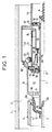
- a breaking chamber will be described; it is understood that a high-voltage circuit breaker may comprise, for each phase, several breaking chambers of the type which will now be described.
- the reference 1 designates an insulating envelope, preferably of porcelain, delimiting a chamber 2 filled with a gas with good dielectric properties, for example sulfur hexafluoride under a pressure of a few bars.
- the fixed assembly comprises an arcing contact 3, consisting of a metal tube whose end 3A is made of a material resistant to the effects of the arcing, by example an alloy based on tungsten.
- the fixed assembly also includes a main contact 4 consisting of fingers protected by a corona hood 5. The arcing contact and the fixed contact are electrically connected to a first socket, not shown.
- the movable assembly comprises an operating part 6, consisting of a tube of insulating material passing through the chamber 2 in a sealed manner and connected to a mechanism not shown.
- a metal assembly comprising two tubes 7 and 8, coaxial and connected by a metal ring 9. These tubes and this ring are preferably made in one piece from machining.
- the tube 7 constitutes the movable arcing contact; its end 7A is made of material resistant to the effects of the arc and cooperates with the contact 3-3A.
- the tube 8 has a first end 8A, of reduced diameter, and carrying a blowing nozzle 10 made of insulating material.
- the tubular portion 8A constitutes the main movable contact of the circuit breaker and cooperates, when the circuit breaker is in the engaged position, as shown in FIG. 1, with the fingers 4.
- the contact is effected by a portion of external cylindrical surface of the bead 8B.
- bead 8B preferably forms a single piece with the tubes 7 and 8 and the crown 9.
- the piston includes seals 17; it is provided with a calibrated valve 18 to limit the pressure inside the volume V1; this valve will be used, as we will see, when cutting low currents.
- the piston finally comprises a one-way valve 19, authorizing the passage of gas only from the outside to the inside of the volume V1; this valve is a simple washer applied to holes 20 passing through the piston.
- the crown 9 is pierced with holes 9A.
- the bead 8B carries, on a cylindrical inner surface, sliding electrical contacts 22 bearing on the tube 14.
- the bead 8B is pierced with holes 23 intended to lighten it and facilitate the circulation of the gas.
- the tube 14 and the tube 11 carry, on either side of the insulating portion 15 two auxiliary contact elements 25 and 26 intended to form a secondary arc.
- These elements consist of tube portions whose ends are made of an alloy resistant to the effects of the arc.
- the contacts 25 and 26 cooperate with a switching tube fixed to the tube 7, therefore movable with it, and comprising an insulating portion 28 and a metal portion 29 the end of which is made of material resistant to the effects of the arc.
- the circuit breaker further comprises a metal piston 30, integral with the operating tube 6, provided with a gasket 31 and a one-way valve 32 allowing the passage of gas only from the outside to the inside of the volume V2 constituted by the tubes 7 and 14, and the pistons 16 and 30.
- the circuit breaker works as follows: in the on position ( Figure 1), the current flows through the fingers 4, the tube 8A-8-8B, the fingers 13, the crown 12 and the tube 11.
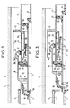
- the operating tube is actuated and moves to the right of the figure.
- the main contacts 4 and 8A separate (figure 2) and the current is switched on the arcing contacts 3 and 7A; the fingers 13 leave the bead 8A, but the contacts 25 and 26 come into contact with the metal portion of the switching tube; in this way, the current takes the following path: the tube 3, the tube 7, the crown 9, the tube 8, the bead 8B, the contacts 22, the tube 14, the contact 25, the tube 29, the contact 26 and tube 11.
- the closing of the circuit breaker is caused by the movement to the left of the figures of the operating tube 6.
- the valves 19 open during this maneuver, so that there is no need to overcome either depression or overpressure; the closing operation also requires only a low operating energy.
- the circuit breaker of the invention has a simple structure, therefore economical, compact, therefore robust and rigid, without electrical contacts in the arcing zones, therefore of reduced maintenance.
- the invention applies to the production of high voltage circuit breakers.
Landscapes
- Circuit Breakers (AREA)
- Arc-Extinguishing Devices That Are Switches (AREA)
- Circuit Arrangements For Discharge Lamps (AREA)
- Arc Welding Control (AREA)
- Lasers (AREA)
- Organic Insulating Materials (AREA)
Abstract
Description
La présente invention est relative à un disjoncteur à gaz diélectrique à autosoufflage, du type comprenant des contacts supplémentaires permettant de générer, lors d'une manoeuvre d'ouverture, un arc secondaire en série avec l'arc principal, l'énergie de cet arc secondaire étant utilisée pour la manoeuvre de l'appareil.The present invention relates to a dielectric gas circuit breaker with self-blowing, of the type comprising additional contacts making it possible to generate, during an opening operation, a secondary arc in series with the main arc, the energy of this arc secondary being used to operate the device.
Un disjoncteur de ce type a par exemple été décrit dans le brevet français n° 2 610 763.A circuit breaker of this type has for example been described in French Patent No. 2,610,763.
L'invention concerne plus précisément un disjoncteur à haute tension à gaz diélectrique sous pression, comprenant pour chaque phase au moins une chambre de coupure comportant une enveloppe isolante remplie dudit gaz à l'intérieur de laquelle sont disposés :
- un ensemble fixe comprenant un contact principal fixe et un contact d'arc fixe reliés électriquement à une première prise de courant,
- un ensemble mobile comprenant un organe de manoeuvre solidaire d'une pièce formée d'un premier tube constituant le contact d'arc mobile, d'un second tube, coaxial audit premier tube, dont une première extrémité constitue le contact principal mobile et portant une buse de soufflage, lesdits premier et second tubes délimitant un volume de soufflage fermé par une couronne percée reliant lesdits tubes et par un piston fixe de soufflage,
- deux contacts d'arc auxiliaires disposés dans un second volume situé du côté opposé au volume de soufflage par rapport au piston fixe de soufflage, qui est maintenu par un troisième tube métallique coaxial au premier tube et délimitant, avec ce dernier et un second piston solidaire dudit premier tube, ledit second volume,
ledit second tube ayant une seconde extrémité en contact électrique avec ledit troisième tube à l'extérieur de ce dernier,
l'un desdits contacts auxiliaires étant fixé audit troisième tube.The invention relates more precisely to a high voltage circuit breaker with pressurized dielectric gas, comprising for each phase at least one breaking chamber comprising an insulating envelope filled with said gas inside which are arranged:
- a fixed assembly comprising a fixed main contact and a fixed arcing contact electrically connected to a first socket outlet,
- a mobile assembly comprising an operating member integral with a part formed by a first tube constituting the movable arcing contact, by a second tube, coaxial with said first tube, one first end of which constitutes the movable main contact and carrying a blowing nozzle, said first and second tubes delimiting a blowing volume closed by a pierced crown connecting said tubes and by a fixed blowing piston,
- two auxiliary arcing contacts arranged in a second volume located on the side opposite the blowing volume relative to the fixed blowing piston, which is held by a third metal tube coaxial with the first tube and delimiting, with the latter and a second piston integral of said first tube, said second volume,
said second tube having a second end in electrical contact with said third tube outside of the latter,
one of said auxiliary contacts being fixed to said third tube.
Un tel disjoncteur est décrit dans le document de brevet EP-A-0 334 181.Such a circuit breaker is described in patent document EP-A-0 334 181.
Un but de la présente invention est de réaliser un disjoncteur du type précité de réalisation simple, notamment dans la partie génératrice de l'arc secondaire.An object of the present invention is to provide a circuit breaker of the aforementioned type of simple embodiment, in particular in the generating part of the secondary arc.
Un autre but de l'invention est de réaliser un disjoncteur ne comportant pas de contacts coulissants dans la zone de l'arc secondaire; cette zone, en effet, est polluée par les produits de décomposition du gaz diélectrique, ce qui peut provoquer une dégradation de la qualité des contacts coulissants.Another object of the invention is to produce a circuit breaker not comprising sliding contacts in the area of the secondary arc; this area, in fact, is polluted by the decomposition products of the dielectric gas, which can cause a degradation of the quality of the sliding contacts.
Un autre but de l'invention est de réaliser un disjoncteur ne comportant aucun piston isolant, dont la réalisation est onéreuse et qui est sujet à usure nécessitant un remplacement fréquent.Another object of the invention is to provide a circuit breaker comprising no insulating piston, the construction of which is expensive and which is subject to wear requiring frequent replacement.
Un autre but de l'invention est de réaliser un disjoncteur dont l'équipage mobile est léger, de sorte qu'il ne nécessite pour son fonctionnement qu'une faible énergie de manoeuvre.Another object of the invention is to provide a circuit breaker with a mobile assembly which is light, so that it requires only a small operating energy for its operation.
Pour ce faire, selon l'invention, dans le disjoncteur selon le préambule de la revendication 1 ledit troisième tube est fixé par une portion tubulaire isolante à un quatrième tube relié électriquement à une seconde prise de courant du disjoncteur, ledit second tube a sa seconde extrémité également en contact électrique avec des doigts reliés électriquement audit quatrième tube et l'autre desdits contacts auxiliaires est fixé audit quatrième tube, lesdits contacts auxiliaires venant en contact avec un tube solidaire de l'ensemble mobile et comprenant une portion isolante et une portion métallique, la position et la longueur respective de ces deux portions tubulaires étant choisies pour qu'en position enclenchée, l'un au moins des contacts auxiliaires soit en contact avec la portion isolante et pour qu'au cours d'une manoeuvre d'ouverture, les deux contacts auxiliaires viennent d'abord simultanément en contact avec la portion métallique, l'un au moins desdits contacts auxiliaires quittant ensuite cette portion métallique.To do this, according to the invention, in the circuit breaker according to the preamble of claim 1 said third tube is fixed by an insulating tubular portion to a fourth tube electrically connected to a second outlet of the circuit breaker, said second tube has its second end also in electrical contact with fingers electrically connected to said fourth tube and the other of said auxiliary contacts is fixed to said fourth tube, said auxiliary contacts coming into contact with a tube integral with the movable assembly and comprising an insulating portion and a metal portion , the position and the respective length of these two tubular portions being chosen so that in the engaged position, at least one of the auxiliary contacts is in contact with the insulating portion and so that during an opening operation, the two auxiliary contacts first come simultaneously into contact with the metal portion, at least one of said auxiliary contacts then leaving this metal portion.
Dans une forme particulière de réalisation, la seconde extrémité dudit second tube est conformée en bourrelet portant une portion cylindrique extérieure sur laquelle s'appuient lesdits doigts et une portion cylindrique intérieure portant des contacts glissants coopérant avec ledit quatrième tube.In a particular embodiment, the second end of said second tube is shaped as a bead carrying an outer cylindrical portion on which said fingers rest and a portion internal cylindrical bearing sliding contacts cooperating with said fourth tube.
Le piston de soufflage est muni d'un clapet unidirectionnel taré laissant passer le gaz de l'intérieur vers l'extérieur du volume de soufflage.The blowing piston is fitted with a calibrated one-way valve letting the gas pass from the inside to the outside of the blowing volume.
Le piston de soufflage est muni d'un clapet unidirectionnel n'autorisant le passage du gaz que de l'extérieur vers l'intérieur du volume de soufflage.The blowing piston is fitted with a one-way valve allowing the passage of gas only from the outside to the inside of the blowing volume.
Le second piston est muni d'un clapet unidirectionnel n'autorisant le passage du gaz que de l'extérieur vers l'intérieur du second volume.The second piston is fitted with a one-way valve allowing the passage of gas only from the outside to the inside of the second volume.
L'invention sera bien comprise par la description donné ci-après d'un exemple de réalisation de l'invention, en référence au dessin annexé dans lequel:
- la figure 1 est une vue schématique partielle en demi-coupe axiale d'une chambre de coupure d'un disjoncteur selon l'invention, représenté en position enclenchée,
- la figure 2 est une vue schématique partielle en demi-coupe axiale de la même chambre, représentée en début de déclenchement,
- la figure 3 est une vue schématique partielle de la même chambre, représentée dans une phase postérieure de la manoeuvre de déclenchement.
- FIG. 1 is a partial schematic view in axial half-section of a breaking chamber of a circuit breaker according to the invention, shown in the engaged position,
- FIG. 2 is a partial schematic view in axial half-section of the same chamber, shown at the start of triggering,
- Figure 3 is a partial schematic view of the same chamber, shown in a later phase of the triggering operation.
Dans ce qui suit, on décrira une chambre de coupure; il est bien entendu qu'un disjoncteur à haute tension peut comporter, pour chaque phase, plusieurs chambres de coupure du type qui va être décrit maintenant.In what follows, a breaking chamber will be described; it is understood that a high-voltage circuit breaker may comprise, for each phase, several breaking chambers of the type which will now be described.
Dans les figures, la référence 1 désigne une enveloppe isolante, de préférence en porcelaine, délimitant une chambre 2 remplie d'un gaz à bonnes propriétés diélectrique, par exemple l'hexafluorure de soufre sous une pression de quelques bars.In the figures, the reference 1 designates an insulating envelope, preferably of porcelain, delimiting a chamber 2 filled with a gas with good dielectric properties, for example sulfur hexafluoride under a pressure of a few bars.
L'ensemble fixe comprend un contact d'arc 3, constitué d'un tube métallique dont l'extrémité 3A est réalisée en un matériau résistant aux effets de l'arc, par exemple un alliage à base de tungstène. L'ensemble fixe comprend également un contact principal 4 constitué de doigts protégés par un capot pare-effluves 5. Le contact d'arc et le contact fixe sont reliés électriquement à une première prise de courant, non représentée.The fixed assembly comprises an arcing contact 3, consisting of a metal tube whose
L'équipage mobile comprend une pièce de manoeuvre 6, constituée d'un tube en matériau isolant traversant la chambre 2 de manière étanche et relié à un mécanisme non représenté.The movable assembly comprises an
A la pièce de manoeuvre 6 est relié un ensemble métallique comprenant deux tubes 7 et 8, coaxiaux et reliés par une couronne métallique 9. Ces tubes et cette couronne sont de préférence réalisés en une seule pièce venue d'usinage.To the
Le tube 7 constitue le contact d'arc mobile; son extrémité 7A est réalisée en matériau résistant aux effets de l'arc et coopère avec le contact 3-3A.The
Le tube 8 possède une première extrémité 8A, de diamètre réduit, et portant une buse de soufflage 10 en matériau isolant.The
La portion tubulaire 8A constitue le contact principal mobile du disjoncteur et coopère, lorsque le disjoncteur est en position enclenchée, comme le montre la figure 1, avec les doigts 4.The
Un tube fixe métallique 11, relié électriquement à une seconde prise de courant du disjoncteur, non représentée, porte une couronne 12 servant de support à des doigts métalliques 13, venant en contact électrique, lorsque le disjoncteur est en position enclenchée, avec une extrémité 8B du tube 8, réalisée sous la forme d'un bourrelet plus épais que le tube. Le contact s'effectue par une portion de surface cylindrique extérieure du bourrelet 8B.A
Là encore, on doit comprendre que le bourrelet 8B forme de préférence une seule et même pièce avec les tubes 7 et 8 et la couronne 9.Again, it should be understood that the
Un tube métallique 14, de préférence de diamètre voisin de celui du tube 11, et fixé à ce dernier par une portion tubulaire 15 en matériau isolant, est relié mécaniquement à un piston métallique 16, pouvant coulisser dans le volume annulaire V1 délimité par les tubes 7 et 8 et la couronne 9. On a compris que les tubes 14 et 15, les contacts 13 ainsi que le piston 16, sont des éléments fixes du disjoncteur puisqu'ils sont tous fixés au tube fixe 11.A
Le piston comprend des joints d'étanchéité 17; il est muni d'un clapet taré 18 pour limiter la pression à l'intérieur du volume V1; ce clapet servira, comme on le verra, lors de la coupure des courants de faible intensité. Le piston comprend enfin un clapet unidirectionnel 19, n'autorisant le passage du gaz que de l'extérieur vers l'intérieur du volume V1; ce clapet est une simple rondelle s'appliquant sur des trous 20 traversant le piston.The piston includes
Pour permettre le passage du gaz à travers la buse 10, la couronne 9 est percée de trous 9A.To allow gas to pass through the
Le bourrelet 8B porte, sur une surface intérieure cylindrique, des contacts électriques glissants 22 en appui sur le tube 14. Le bourrelet 8B est percé de trous 23 destinés à l'alléger et à faciliter la circulation du gaz.The
Le tube 14 et le tube 11 portent, de part et d'autre de la portion isolante 15 deux éléments de contacts auxiliaires 25 et 26 destinés à former un arc secondaire. Ces éléments sont constitués de portions de tube dont les extrémités sont réalisées en un alliage résistant aux effets de l'arc.The
Les contacts 25 et 26 coopèrent avec un tube de commutation fixé au tube 7, donc mobile avec lui, et comprenant une portion isolante 28 et une portion métallique 29 dont l'extrémité est réalisée en matériau résistant aux effets de l'arc.The
Le disjoncteur comprend en outre un piston métallique 30, solidaire du tube de manoeuvre 6, muni d'un joint d'étanchéité 31 et d'un clapet unidirectionnel 32 n'autorisant le passage du gaz que de l'extérieur vers l'intérieur du volume V2 constitué par les tubes 7 et 14, et les pistons 16 et 30.The circuit breaker further comprises a
Le fonctionnement du disjoncteur est le suivant : en position enclenchée (figure 1), le courant traverse les doigts 4, le tube 8A-8-8B, les doigts 13, la couronne 12 et le tube 11.The circuit breaker works as follows: in the on position (Figure 1), the current flows through the
Il s'agit des courants de court-circuit.These are short-circuit currents.
Le tube de manoeuvre est actionné et se déplace vers la droite de la figure.The operating tube is actuated and moves to the right of the figure.
Les contacts principaux 4 et 8A se séparent (figure 2) et le courant est commuté sur les contacts d'arc 3 et 7A; les doigts 13 quittent le bourrelet 8A, mais les contacts 25 et 26 viennent en contact avec la portion métallique du tube de commutation; de la sorte, le courant emprunte le chemin suivant : le tube 3, le tube 7, la couronne 9, le tube 8, le bourrelet 8B, les contacts 22, le tube 14, le contact 25, le tube 29, le contact 26 et le tube 11.The
Lorsque les contacts d'arc 3A-7A se séparent (figure 3), un arc primaire 50 jaillit entre eux; à peu près en même temps, les contacts 25 et 29 se séparent, et un arc secondaire 51 jaillit dans le volume V2. Cet arc secondaire échauffe le gaz du volume V2, ce qui produit une augmentation de pression qui, d'une part vient aider à la manoeuvre d'ouverture en apportant de l'énergie au tube de manoeuvre par action sur le piston 30 et, d'autre part vient contribuer au soufflage de l'arc primaire en verrouillant le clapet limiteur 18, ce qui fait que tout le gaz du volume V1 est soufflé.When the
Il s'agit des courants inférieurs ou égaux au courant nominal de l'installation.These are currents less than or equal to the nominal current of the installation.
Le fonctionnement est voisin de celui qui a été décrit précédemment mais cette fois-ci, le courant à couper est faible, de sorte que l'arc secondaire 51 apporte une énergie insuffisante pour fermer le clapet 18 contre la pression régnant dans le volume V1. La pression dans le volume V1 est limitée par le clapet taré 18.The operation is close to that which has been described above, but this time, the current to be cut is low, so that the
Il n'y a pas de dépression dans le volume V2, car le clapet 32 s'ouvre et remplit de gaz le volume V2.There is no vacuum in the volume V2, because the
La fermeture du disjoncteur est provoquée par le déplacement vers la gauche des figures du tube de manoeuvre 6. Les clapets 19 s'ouvre au cours de cette manoeuvre, de sorte qu'il n'y a à vaincre ni dépression, ni surpression; la manoeuvre de fermeture ne nécessite également qu'une faible énergie de manoeuvre.The closing of the circuit breaker is caused by the movement to the left of the figures of the operating
Le disjoncteur de l'invention possède une structure simple, donc économique, compacte, donc robuste et rigide, sans contacts électriques dans les zones d'arc, donc d'entretien plus réduit.The circuit breaker of the invention has a simple structure, therefore economical, compact, therefore robust and rigid, without electrical contacts in the arcing zones, therefore of reduced maintenance.
L'invention s'applique à la réalisation de disjoncteur à haute tension.The invention applies to the production of high voltage circuit breakers.
Claims (5)
- A high tension circuit-breaker containing dielectric gas under pressure and including, at least one interrupting chamber per phase, each chamber comprising an insulating case filled with said gas, and containing the following:
an assembly comprising a fixed main contact (4) and a fixed arcing contact (3-3A) which are electrically connected to a first terminal;
a moving assembly comprising a drive member (6) which is integral with a part formed by a first tube (7-7A) constituting the moving arcing contact, and with a second tube (8-8A-8B) which is coaxial with said first tube and which has a first end (8A) constituting the moving main contact and carrying a blast nozzle (10), said first and second tubes delimiting a blast first volume (V1) closed by a perforated annulus (9) interconnecting said tubes and by a fixed blast piston (16); and
two secondary arcing contacts (25, 26) disposed in a second volume (V2) situated on the opposite side of the fixed blast piston (16) to the blast volume, which blast piston is supported by a third metal tube (14) which is coaxial to the first tube (7-7A) and which co-operates therewith and with a second piston (30) which is an integral part of the first tube (7-7A) to delimit said second volume (V2), said second tube having its second end (8B) in electrical contact with the outside of said third tube one contact (25) of said secondary arcing contacts being fixed to said third tube (14), the circuit-breaker being characterized in that said third tube (14) is fixed by an insulating tubular portion (15) to a fourth tube (11) which is electrically connected to a second terminal of the circuit-breaker, in that said second tube also has its second end (8B) in electrical contact with the fingers (13) electrically connected to said fourth tube (11), and in that the other one of said secondary contacts (26) is fixed to said fourth tube, said secondary arcing contacts making contact with a tube (28-29) which is integral with the moving assembly and which comprises an insulating portion (28) and a metal portion (29), the respective positions and lengths of these two tubular portions being chosen so that in the engaged position, at least one contact (26) of the secondary arcing contacts makes contact with the insulating portion (28), and so that during opening, the two secondary arcing contacts initially make contact simultaneously with the metal portion (29), and later at least one (25) of said secondary arcing contacts leaves this metal portion (29). - A circuit-breaker according to claim 1, characterized in that the second end (8B) of said second tube (8) is formed into a collar having an external cylindrical portion against which said fingers (13) bear and having an internal cylindrical portion fitted with sliding contacts (22) which co-operate with said fourth tube (14).
- A circuit-breaker according to claim 1 or 2, characterized in that the fixed blast piston (16) is fitted with a calibrated non-return valve (18) which allows the gas to pass from the inside to the outside of the blast volume (V1).
- A circuit-breaker according to any one of claims 1 to 3, characterized in that said fixed blast piston (16) is fitted with a non-return valve (19) allowing gas to pass only from the outside to the inside of the blast volume (V1).
- A circuit-breaker according to any one of claims 1 to 4, characterized in that the second piston (30) is fitted with a non-return valve allowing the gas to pass only from the outside to the inside of the second volume (V2).
Applications Claiming Priority (2)
| Application Number | Priority Date | Filing Date | Title |
|---|---|---|---|
| FR9005326A FR2661550B1 (en) | 1990-04-26 | 1990-04-26 | HIGH VOLTAGE CIRCUIT BREAKER WITH SERIES ARC. |
| FR9005326 | 1990-04-26 |
Publications (2)
| Publication Number | Publication Date |
|---|---|
| EP0456025A1 EP0456025A1 (en) | 1991-11-13 |
| EP0456025B1 true EP0456025B1 (en) | 1995-03-01 |
Family
ID=9396115
Family Applications (1)
| Application Number | Title | Priority Date | Filing Date |
|---|---|---|---|
| EP91106454A Expired - Lifetime EP0456025B1 (en) | 1990-04-26 | 1991-04-22 | High voltage circuit interrupter with arc in series |
Country Status (10)
| Country | Link |
|---|---|
| US (1) | US5160818A (en) |
| EP (1) | EP0456025B1 (en) |
| JP (1) | JP2563855B2 (en) |
| CN (1) | CN1023924C (en) |
| AT (1) | ATE119312T1 (en) |
| BR (1) | BR9101564A (en) |
| CA (1) | CA2041234C (en) |
| DE (1) | DE69107670T2 (en) |
| ES (1) | ES2070357T3 (en) |
| FR (1) | FR2661550B1 (en) |
Families Citing this family (6)
| Publication number | Priority date | Publication date | Assignee | Title |
|---|---|---|---|---|
| FR2720188B1 (en) * | 1994-05-19 | 1996-06-14 | Gec Alsthom T & D Sa | Reduced auto-compression circuit breaker. |
| DE19524217A1 (en) * | 1995-07-03 | 1997-01-09 | Abb Research Ltd | Circuit breaker |
| CN101930871B (en) * | 2010-08-25 | 2012-11-21 | 中国西电电气股份有限公司 | Arc extinguish chamber with high current-carrying capability for high-voltage switch equipment |
| KR101483086B1 (en) * | 2013-05-21 | 2015-01-16 | 한국전기연구원 | Hybrid extinction type gas circuit breaker |
| CN106328430B (en) * | 2016-08-25 | 2018-08-07 | 中国西电电气股份有限公司 | A kind of arc-chutes of series connection plenum chamber |
| US10026571B1 (en) * | 2017-03-31 | 2018-07-17 | General Electric Technology Gmbh | Switching chamber for a gas-insulated circuit breaker comprising an optimized thermal channel |
Family Cites Families (8)
| Publication number | Priority date | Publication date | Assignee | Title |
|---|---|---|---|---|
| DE2349263C2 (en) * | 1973-10-01 | 1982-08-26 | Brown, Boveri & Cie Ag, 6800 Mannheim | Electric pressure gas switch |
| JP2528100B2 (en) * | 1986-07-08 | 1996-08-28 | 株式会社日立製作所 | Patch type gas circuit breaker |
| FR2610763B1 (en) * | 1987-02-09 | 1989-04-28 | Alsthom | LOW ENERGY MANEUVER CIRCUIT BREAKER |
| FR2619246B1 (en) * | 1987-08-03 | 1989-11-17 | Alsthom | HIGH OR MEDIUM VOLTAGE CIRCUIT BREAKER UNDER PRESSURE WITH CURING ENERGY TAKEN FROM THE ARC |
| FR2629260B1 (en) * | 1988-03-23 | 1994-07-08 | Alsthom | HIGH-VOLTAGE LOW-ENERGY CIRCUIT BREAKER |
| FR2638564B1 (en) * | 1988-11-02 | 1990-11-30 | Alsthom Gec | HIGH VOLTAGE CIRCUIT BREAKER WITH DIELECTRIC GAS UNDER PRESSURE |
| FR2647949B1 (en) * | 1989-05-31 | 1994-02-18 | Gec Alsthom Sa | HIGH VOLTAGE CIRCUIT BREAKER WITH SUPPLY DIELECTRIC GAS |
| FR2649531B1 (en) * | 1989-07-04 | 1995-11-10 | Alsthom Gec | HIGH OR MEDIUM VOLTAGE CIRCUIT BREAKER |
-
1990
- 1990-04-26 FR FR9005326A patent/FR2661550B1/en not_active Expired - Lifetime
-
1991
- 1991-04-18 BR BR919101564A patent/BR9101564A/en not_active Application Discontinuation
- 1991-04-22 US US07/688,797 patent/US5160818A/en not_active Expired - Fee Related
- 1991-04-22 EP EP91106454A patent/EP0456025B1/en not_active Expired - Lifetime
- 1991-04-22 DE DE69107670T patent/DE69107670T2/en not_active Expired - Fee Related
- 1991-04-22 ES ES91106454T patent/ES2070357T3/en not_active Expired - Lifetime
- 1991-04-22 AT AT91106454T patent/ATE119312T1/en not_active IP Right Cessation
- 1991-04-24 CN CN91103342.4A patent/CN1023924C/en not_active Expired - Fee Related
- 1991-04-25 CA CA002041234A patent/CA2041234C/en not_active Expired - Fee Related
- 1991-04-26 JP JP3097392A patent/JP2563855B2/en not_active Expired - Lifetime
Also Published As
| Publication number | Publication date |
|---|---|
| ES2070357T3 (en) | 1995-06-01 |
| EP0456025A1 (en) | 1991-11-13 |
| FR2661550A1 (en) | 1991-10-31 |
| DE69107670D1 (en) | 1995-04-06 |
| BR9101564A (en) | 1991-12-10 |
| ATE119312T1 (en) | 1995-03-15 |
| JPH05159671A (en) | 1993-06-25 |
| CN1056767A (en) | 1991-12-04 |
| FR2661550B1 (en) | 1992-06-12 |
| CN1023924C (en) | 1994-03-02 |
| CA2041234C (en) | 1994-11-22 |
| DE69107670T2 (en) | 1995-06-29 |
| US5160818A (en) | 1992-11-03 |
| JP2563855B2 (en) | 1996-12-18 |
Similar Documents
| Publication | Publication Date | Title |
|---|---|---|
| EP0388323A1 (en) | Autoexpansion electric circuit breaker with insulating gas | |
| EP0821382B1 (en) | High-voltage circuit breaker of self-blasting type | |
| EP0591039B1 (en) | H.T. self-blast circuit breaker having an arc chamber with reduced gas compression | |
| EP0367072B1 (en) | Gas-blast circuit interrupter for highpotential | |
| EP0302390B1 (en) | High or medium voltage gas blast circuit breaker with opening energy taken from the arc energy | |
| EP0456025B1 (en) | High voltage circuit interrupter with arc in series | |
| CA2206950C (en) | High-voltage switch with resistor insertion upon closing | |
| EP0807946A1 (en) | High-voltage gas-blast puffer type circuit-breaker | |
| FR2576144A1 (en) | HIGH VOLTAGE, COMPRESSED GAS, LOW-ENERGY CIRCUIT BREAKER | |
| EP0398211B1 (en) | High tension gas blast circuit breaker | |
| FR2629260A1 (en) | HIGH-VOLTAGE LOW-ENERGY CIRCUIT BREAKER | |
| EP0415098B1 (en) | Self-blast circuit breaker for medium voltage | |
| FR2610763A1 (en) | Circuit breaker with low actuating energy | |
| EP0398213B1 (en) | Middle high-voltage circuit breaker for high nominal current | |
| EP0450567B1 (en) | High- or medium voltage circuit breaker with abutting arcing contacts | |
| EP0458236B1 (en) | Medium high voltage circuit breaker | |
| CA2017804C (en) | Dielectric gas blast high voltage circuit-breaker | |
| EP0785562A1 (en) | Circuit breaker having contacts with double movement | |
| EP0664552A1 (en) | Puffer-type gas-blast circuit breaker with double movement | |
| EP0515268A1 (en) | Varistor insertion device incorporated in an H.T. circuit breaker | |
| CH688702A5 (en) | High-voltage switch having an arc extinguishing chamber variable blast volume. | |
| FR2607621A1 (en) | HIGH VOLTAGE CIRCUIT BREAKER WITH DIELECTRIC GAS WITH CLOSURE RESISTANCE | |
| EP0701264A1 (en) | Gas blast circuitbreaker with semi mobile piston | |
| FR2509521A1 (en) | HIGH-VOLTAGE CIRCUIT BREAKER WITH ENCLOSURE CONTAINING AN INSULATING GAS | |
| FR2556496A1 (en) | Gas blast circuit breaker with fixed and moving contacts |
Legal Events
| Date | Code | Title | Description |
|---|---|---|---|
| PUAI | Public reference made under article 153(3) epc to a published international application that has entered the european phase |
Free format text: ORIGINAL CODE: 0009012 |
|
| AK | Designated contracting states |
Kind code of ref document: A1 Designated state(s): AT BE CH DE DK ES FR GB GR IT LI LU NL SE |
|
| 17P | Request for examination filed |
Effective date: 19911218 |
|
| 17Q | First examination report despatched |
Effective date: 19940125 |
|
| GRAA | (expected) grant |
Free format text: ORIGINAL CODE: 0009210 |
|
| AK | Designated contracting states |
Kind code of ref document: B1 Designated state(s): AT BE CH DE DK ES FR GB GR IT LI LU NL SE |
|
| PG25 | Lapsed in a contracting state [announced via postgrant information from national office to epo] |
Ref country code: NL Free format text: LAPSE BECAUSE OF NON-PAYMENT OF DUE FEES Effective date: 19950301 Ref country code: GR Free format text: LAPSE BECAUSE OF FAILURE TO SUBMIT A TRANSLATION OF THE DESCRIPTION OR TO PAY THE FEE WITHIN THE PRESCRIBED TIME-LIMIT Effective date: 19950301 Ref country code: GB Effective date: 19950301 Ref country code: DK Effective date: 19950301 |
|
| REF | Corresponds to: |
Ref document number: 119312 Country of ref document: AT Date of ref document: 19950315 Kind code of ref document: T |
|
| REF | Corresponds to: |
Ref document number: 69107670 Country of ref document: DE Date of ref document: 19950406 |
|
| PG25 | Lapsed in a contracting state [announced via postgrant information from national office to epo] |
Ref country code: LU Free format text: LAPSE BECAUSE OF NON-PAYMENT OF DUE FEES Effective date: 19950430 Ref country code: BE Effective date: 19950430 |
|
| ITF | It: translation for a ep patent filed | ||
| REG | Reference to a national code |
Ref country code: ES Ref legal event code: FG2A Ref document number: 2070357 Country of ref document: ES Kind code of ref document: T3 |
|
| NLV1 | Nl: lapsed or annulled due to failure to fulfill the requirements of art. 29p and 29m of the patents act | ||
| GBV | Gb: ep patent (uk) treated as always having been void in accordance with gb section 77(7)/1977 [no translation filed] |
Effective date: 19950301 |
|
| BERE | Be: lapsed |
Owner name: S.A. GEC ALSTHOM Effective date: 19950430 |
|
| PLBE | No opposition filed within time limit |
Free format text: ORIGINAL CODE: 0009261 |
|
| STAA | Information on the status of an ep patent application or granted ep patent |
Free format text: STATUS: NO OPPOSITION FILED WITHIN TIME LIMIT |
|
| 26N | No opposition filed | ||
| PGFP | Annual fee paid to national office [announced via postgrant information from national office to epo] |
Ref country code: SE Payment date: 19970324 Year of fee payment: 7 Ref country code: AT Payment date: 19970324 Year of fee payment: 7 |
|
| PGFP | Annual fee paid to national office [announced via postgrant information from national office to epo] |
Ref country code: CH Payment date: 19970326 Year of fee payment: 7 |
|
| PGFP | Annual fee paid to national office [announced via postgrant information from national office to epo] |
Ref country code: ES Payment date: 19970418 Year of fee payment: 7 |
|
| PG25 | Lapsed in a contracting state [announced via postgrant information from national office to epo] |
Ref country code: AT Free format text: LAPSE BECAUSE OF NON-PAYMENT OF DUE FEES Effective date: 19980422 |
|
| PG25 | Lapsed in a contracting state [announced via postgrant information from national office to epo] |
Ref country code: SE Free format text: LAPSE BECAUSE OF NON-PAYMENT OF DUE FEES Effective date: 19980423 Ref country code: ES Free format text: LAPSE BECAUSE OF NON-PAYMENT OF DUE FEES Effective date: 19980423 |
|
| PG25 | Lapsed in a contracting state [announced via postgrant information from national office to epo] |
Ref country code: LI Free format text: LAPSE BECAUSE OF NON-PAYMENT OF DUE FEES Effective date: 19980430 Ref country code: CH Free format text: LAPSE BECAUSE OF NON-PAYMENT OF DUE FEES Effective date: 19980430 |
|
| REG | Reference to a national code |
Ref country code: CH Ref legal event code: PL |
|
| EUG | Se: european patent has lapsed |
Ref document number: 91106454.1 |
|
| PGFP | Annual fee paid to national office [announced via postgrant information from national office to epo] |
Ref country code: FR Payment date: 19990324 Year of fee payment: 9 |
|
| PGFP | Annual fee paid to national office [announced via postgrant information from national office to epo] |
Ref country code: DE Payment date: 20000320 Year of fee payment: 10 |
|
| REG | Reference to a national code |
Ref country code: ES Ref legal event code: FD2A Effective date: 20000403 |
|
| PG25 | Lapsed in a contracting state [announced via postgrant information from national office to epo] |
Ref country code: FR Free format text: LAPSE BECAUSE OF NON-PAYMENT OF DUE FEES Effective date: 20001229 |
|
| REG | Reference to a national code |
Ref country code: FR Ref legal event code: ST |
|
| PG25 | Lapsed in a contracting state [announced via postgrant information from national office to epo] |
Ref country code: DE Free format text: LAPSE BECAUSE OF NON-PAYMENT OF DUE FEES Effective date: 20020201 |
|
| PG25 | Lapsed in a contracting state [announced via postgrant information from national office to epo] |
Ref country code: IT Free format text: LAPSE BECAUSE OF NON-PAYMENT OF DUE FEES;WARNING: LAPSES OF ITALIAN PATENTS WITH EFFECTIVE DATE BEFORE 2007 MAY HAVE OCCURRED AT ANY TIME BEFORE 2007. THE CORRECT EFFECTIVE DATE MAY BE DIFFERENT FROM THE ONE RECORDED. Effective date: 20050422 |