EP0414514A2 - Cable ducting and method for installing cables through ducts - Google Patents
Cable ducting and method for installing cables through ducts Download PDFInfo
- Publication number
- EP0414514A2 EP0414514A2 EP90309189A EP90309189A EP0414514A2 EP 0414514 A2 EP0414514 A2 EP 0414514A2 EP 90309189 A EP90309189 A EP 90309189A EP 90309189 A EP90309189 A EP 90309189A EP 0414514 A2 EP0414514 A2 EP 0414514A2
- Authority
- EP
- European Patent Office
- Prior art keywords
- duct
- cable
- ribs
- ducts
- spiral
- Prior art date
- Legal status (The legal status is an assumption and is not a legal conclusion. Google has not performed a legal analysis and makes no representation as to the accuracy of the status listed.)
- Granted
Links
Images


Classifications
-
- H—ELECTRICITY
- H02—GENERATION; CONVERSION OR DISTRIBUTION OF ELECTRIC POWER
- H02G—INSTALLATION OF ELECTRIC CABLES OR LINES, OR OF COMBINED OPTICAL AND ELECTRIC CABLES OR LINES
- H02G1/00—Methods or apparatus specially adapted for installing, maintaining, repairing or dismantling electric cables or lines
- H02G1/06—Methods or apparatus specially adapted for installing, maintaining, repairing or dismantling electric cables or lines for laying cables, e.g. laying apparatus on vehicle
- H02G1/08—Methods or apparatus specially adapted for installing, maintaining, repairing or dismantling electric cables or lines for laying cables, e.g. laying apparatus on vehicle through tubing or conduit, e.g. rod or draw wire for pushing or pulling
-
- G—PHYSICS
- G02—OPTICS
- G02B—OPTICAL ELEMENTS, SYSTEMS OR APPARATUS
- G02B6/00—Light guides; Structural details of arrangements comprising light guides and other optical elements, e.g. couplings
- G02B6/44—Mechanical structures for providing tensile strength and external protection for fibres, e.g. optical transmission cables
- G02B6/4439—Auxiliary devices
- G02B6/4459—Ducts; Conduits; Hollow tubes for air blown fibres
-
- H—ELECTRICITY
- H02—GENERATION; CONVERSION OR DISTRIBUTION OF ELECTRIC POWER
- H02G—INSTALLATION OF ELECTRIC CABLES OR LINES, OR OF COMBINED OPTICAL AND ELECTRIC CABLES OR LINES
- H02G9/00—Installations of electric cables or lines in or on the ground or water
- H02G9/06—Installations of electric cables or lines in or on the ground or water in underground tubes or conduits; Tubes or conduits therefor
Definitions
- the present invention relates to cable ducting and to cable installation.
- transmission cable was pulled through a duct which either had no interior ribs or had longitudinal interior ribs.
- An example of the ribbed duct is shown in US-A-4,565,351.
- transmission cable was strung through corrugated ducting, i.e. ducting having transverse ribs.
- Corrugated ducting i.e. ducting having transverse ribs.
- smooth-walled ducting had the highest coefficient of friction, and therefore required high forces to be used when pulling a transmission cable there-through.
- relatively short lengths of transmission cable could be placed underground before the forces built up to the point where the cable itself became endangered.
- Corrugated and longitudinally ribbed ducting reduced surface friction with the cable. Both the longitudinally ribbed and smooth-walled ducts, however, had a tendency to damage the cable sheath. Such damage to the sheath would not normally be discovered until a later date, and replacement of the cable would be necessary. The replacement process was highly undesirable and needlessly expensive.
- Corrugated tubing had a relatively low coefficient of friction relative to the transmission cable, and did not have a tendency to damage the sheathing.
- corrugated ducting is relatively thin and has uneven walls because of the necessity of continuously blow-moulding it during its manufacturing process.
- the thin-walled corrugations had a tendency to stretch or break during field installation because of their own relatively low tensile strength.
- the flexible nature of corrugated tubing also allowed it to rotate and shear.
- the thin wall thickness also wore quickly and perforated when transmission cable was pulled through it.
- the depth of the corrugations is generally two to four times as deep as longitudinal ribs, thus causing the lubricant to well up between successive corrugations and impede normal cable lubrication efforts.
- This invention uses a duct including a polymeric tubing having an inner and outer wall.
- the inner wall has spiral ribs.
- the use of spiral ribs has been found to give the best combination of results when used with a transmission cable for reducing the friction between the cable and the duct, providing structural integrity of the tubing, and not damaging the sheath on the cable.
- the spiral ribs act much like corrugations in that they do not shave off the sheathing because the cable tends to pass over them in a transverse manner.
- the internally spiralled duct is much stronger than corrugated tubing and does not have a tendency to rip or tear during its installation. It is also flexible enough to go around corners.
- the valleys between the spiral ribs also act as a resrvoir for lubricant which is commonly used to reduce friction between the cable and the duct.
- a duct according to the invention for transmission cable and other includes a polymeric tubing having an inner wall and an outer wall. Spiral ribs having peaks and valleys are located along the inner wall, and the valleys are adapted to receive lubrication. The peaks form a surface over which the cable may travel at reduced friction.
- a plurality of takeoff reels 10, 12 and 14 on stands 16, 18 and 20, respectively, are located so that they feed a plurality of ducts 22, 24 and 26 into a feeder tube 30.
- the feeder tube 30, as well as the apparatus for pulling the ducts through an outer duct 32, is described in US-A- 4,296,157; US-A- 4,028,473; and US-A- 4,326,605.
- lubricant is also often used and is fed into the feeder tube with the transmission cable.
- the ducts 22, 24 and 26 are pulled by means of a draw line 32 towards a take-up reel 36 mounted on a stand 38.
- the draw line 32 is attached to the duct, as described in the above-noted US-A- 4,028,473.
- the draw line 32 is wound on the reel 36 and is followed by the duct.
- the duct transmission or other cable enters a work area, such as 40, by means of an outer duct 44 and may be passed back into another outer duct, such as 46 or 48, to relay them to another location.
- the inner wall 50 of the duct 22 has peaks 54 and valleys 56 forming spiral ribs 58 along the interior of the tubing.
- the material which comprises the duct is normally a thermoplastic, such as polyethylene, although other materials are well known in the art.
- the lubricant used with the transmission cable is that such as described in US-A- 4,111,820.
- the use of spiral ribs has been found to reduce dramatically the coefficient of friction without noticeably damaging the cable sheaths or jackets when the cable is pulled through.
- the coefficient of friction (f) of the transmission cable as it passes over the spiral ribs can be measured over various load and velocity conditions by pulling cable through a duct coiled about a fixed drum.
- Load Factors K
- the velocity-compensated load factor (coefficient of friction) is substantially reduced to 0.0764 at the 11.34kg (25 pound) incoming load, whereas its non-spiralled counterpart fused the cable to the duct wall.
- the coefficient of friction is minimized, at between one and three turns per 0.305m (1 ft).
- the duct diameter is not critical, although typically ducts range from 25.4 mm to 152.4 mm (one inch to six inches) inside diameter. Wall thicknesses may also vary, but useful thicknesses are sizes such as Standard Thermoplastic Pipe Dimension Ratio (SIDR) 5 to 21. Rib height preferably is from about 0.127 mm to 3.81 mm (0.005 inch to 0.150 inch), with the preferred being about 0.381 mm (0.015 inch). The rib spacing typically varies between about 0.688 mm and 12.5 mm (0.025 inch and 0.500 inch), with the preferred spacing being 3.175 mm (6.125 inch).
- SIDR Standard Thermoplastic Pipe Dimension Ratio
- the frequency of spirals can range between 32.8 turns per m and 0.16 turns per m (10 revolutions per foot and 0.05 revolution per foot), the preferred being about 1.08 turns per m (0.33 revolution per foot), or one revolution every 0.914 m (three feet).
- the direction of spiral rotation can be altered in a periodic fashion to create a sinusoidal wave, as well, without diminishing the improved effect.
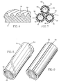
- the outer wall 52 of the duct may be smooth, as shown in Figs. 2 to 4, or, alternatively, as illustrated in Figs. 5 and 6, may be ribbed along the length thereof.
- a spiral rib 59 may be used along the outer wall 52. The spiral nature of the rib will add additional strength, and also will cause a type of interlocking with other ducts if they are placed together as illustrated in Fig.7.
- longitudinal ribs 60 as shown in Fig.6, may be used along the outer wall 52 to aid in inserting the duct through an outer duct. The use of the ribbing reduces friction in this regard, as does the internal spiral ribbing 58.
- the spiral ribbing 58 may be continuous as shown in Fig.5, or it may alternate in direction.
- the benefit of alternating the direction of the spiral rib 58 is that a cable passed through the duct will not have a tendency to rotate with the spiral. By reducing the area of the duct that touches the outer duct, the friction, and therefore the force needed to pull the duct through the outer duct, is substantially reduced.
- a series of ducts 62, 64, and 66 having inner walls with spiral ribs 68, 70, and 72, respectively, are used to hold transmission cables 74, 76 and 78.
- Exterior ribs 82, 84 and 86 interlock with each other, whether spiral or longitudinal, in order to prevent rotation of one duct relative to the other.
- the three conduits shown in Fig.7 may be connected along their length in the moulding process or, alternatively, may be moulded separately and placed in the ground separately.
- Fig.8 illustrates an open trench 90 having side walls 92, 94 and a bottom 96.
- Ducts 100, 102 and 104 are laid in the trench 90 in a generally triangular fashion and are bound together by a band 106.
- the ducts have spiral ribs 108 on their outer wall 110.
- spiral ribs on the inner wall of the duct.
- the ribs 108 may also be longitudinal so that the ducts interlock and do not rotate relative to one another. After the ducts have been laid, they are covered with soil.
- a plough 112 is attached to a large tractor (not shown). As the plough moves forward, or from left to right as shown in Fig.9, the point 114 disrupts the earth and loosens it so that the ducts 116 and 118 having spiral ribs 121, 122 can pass through the hollow inner section, out of the back of the plough and into the ground. In this embodiment, it is not necessary to cover the ducts in a subsequent step. Accordingly, this process is relatively fast. As previously discussed, the optical cables are then passed through the ducts after they have been laid in place.
Landscapes
- Physics & Mathematics (AREA)
- General Physics & Mathematics (AREA)
- Optics & Photonics (AREA)
- Insulated Conductors (AREA)
- Laying Of Electric Cables Or Lines Outside (AREA)
- Electric Cable Installation (AREA)
- Details Of Indoor Wiring (AREA)
- Light Guides In General And Applications Therefor (AREA)
- Rigid Pipes And Flexible Pipes (AREA)
Abstract
Description
- The present invention relates to cable ducting and to cable installation.
- When it was discovered that fibre-optic cable could be used more efficiently than electric wires for the transmission of telephone conversations, a need for an enormous replacement undertaking became apparent. The copper cable that was previously used underground had to be replaced by fibre-optic cable in a cost-efficient manner which would maintain the integrity of the transmission cable.
- When installing the fibre-optic transmission cable, which is usually sheathed in a thermoplastic insulator, there are a number of problems that must be avoided. The plastic sheathing itself must not encounter any sharp surfaces that damage or shave it away to any substantial degree. If this were to happen, exposure of the light guide would occur, along with the pertinent problems. Moreover, tension must not exceed a certain safety margin of the transmission cable or it might break.
- Because of the forces necessary to pull the transmission cable through a duct, it is highly advantageous to lower the friction between the transmission cable and its duct. When the coefficient of friction of the duct is lowered, the resulting lower forces to pull the cable through the duct allow longer lengths to be strung without a relay.
- Previously, transmission cable was pulled through a duct which either had no interior ribs or had longitudinal interior ribs. An example of the ribbed duct is shown in US-A-4,565,351. Alternatively, transmission cable was strung through corrugated ducting, i.e. ducting having transverse ribs. Each of these ducts caused problems. Smooth-walled ducting had the highest coefficient of friction, and therefore required high forces to be used when pulling a transmission cable there-through. As a result, relatively short lengths of transmission cable could be placed underground before the forces built up to the point where the cable itself became endangered.
- Corrugated and longitudinally ribbed ducting reduced surface friction with the cable. Both the longitudinally ribbed and smooth-walled ducts, however, had a tendency to damage the cable sheath. Such damage to the sheath would not normally be discovered until a later date, and replacement of the cable would be necessary. The replacement process was highly undesirable and needlessly expensive.
- Corrugated tubing had a relatively low coefficient of friction relative to the transmission cable, and did not have a tendency to damage the sheathing. However, corrugated ducting is relatively thin and has uneven walls because of the necessity of continuously blow-moulding it during its manufacturing process. Moreover, the thin-walled corrugations had a tendency to stretch or break during field installation because of their own relatively low tensile strength. The flexible nature of corrugated tubing also allowed it to rotate and shear. The thin wall thickness also wore quickly and perforated when transmission cable was pulled through it. The depth of the corrugations is generally two to four times as deep as longitudinal ribs, thus causing the lubricant to well up between successive corrugations and impede normal cable lubrication efforts.
- This invention uses a duct including a polymeric tubing having an inner and outer wall. The inner wall has spiral ribs. The use of spiral ribs has been found to give the best combination of results when used with a transmission cable for reducing the friction between the cable and the duct, providing structural integrity of the tubing, and not damaging the sheath on the cable. The spiral ribs act much like corrugations in that they do not shave off the sheathing because the cable tends to pass over them in a transverse manner. The internally spiralled duct is much stronger than corrugated tubing and does not have a tendency to rip or tear during its installation. It is also flexible enough to go around corners. The valleys between the spiral ribs also act as a resrvoir for lubricant which is commonly used to reduce friction between the cable and the duct.
- A duct according to the invention for transmission cable and other includes a polymeric tubing having an inner wall and an outer wall. Spiral ribs having peaks and valleys are located along the inner wall, and the valleys are adapted to receive lubrication. The peaks form a surface over which the cable may travel at reduced friction.
- The invention is further described, by way of example, with reference to the accompanying drawings, in which:-
- Fig.1 is a schematic representation of the installation of multiple ducts which are surrounded by an outer duct;
- Fig.2 is a longitudinal section of a duct according to this invention;
- Fig.3 is a transverse cross section of the duct of Fig.2;
- Fig.4 is a developed view of internal spiral ribs of the duct of Figs. 2 and 3;
- Fig.5 is a perspective view which illustrates one embodiment of exterior ribs of a duct according to the invention;
- Fig.6 is a similar view which illustrates an alternative embodiment of exterior ribs on the duct;
- Fig.7 is a cross-section which illustrates a plurality of ducts and transmission cables;
- Fig.8 is a schematic representation of the installation of ducts in an open trench; and
- Fig.9 is a schematic representation of the direct installation of ducts by means of a plough.
- As particularly illustrated in Fig.1, a plurality of
takeoff reels stands ducts feeder tube 30. Thefeeder tube 30, as well as the apparatus for pulling the ducts through anouter duct 32, is described in US-A- 4,296,157; US-A- 4,028,473; and US-A- 4,326,605. As described therein, lubricant is also often used and is fed into the feeder tube with the transmission cable. - The
ducts draw line 32 towards a take-up reel 36 mounted on astand 38. Thedraw line 32 is attached to the duct, as described in the above-noted US-A- 4,028,473. Thedraw line 32 is wound on thereel 36 and is followed by the duct. As a result of this invention, the distance from thework area 40 to thework area 42 has been substantially increased for the length of the transmission cable that may be pulled through the duct. At the present time, this distance may be 914 to 1828m (3000 to 6000 feet) with the use of this invention. - Normally, the duct transmission or other cable enters a work area, such as 40, by means of an
outer duct 44 and may be passed back into another outer duct, such as 46 or 48, to relay them to another location. - As particularly illustrated in Figs, 2, 3 and 4, the
inner wall 50 of theduct 22 haspeaks 54 andvalleys 56 formingspiral ribs 58 along the interior of the tubing. The material which comprises the duct is normally a thermoplastic, such as polyethylene, although other materials are well known in the art. The lubricant used with the transmission cable is that such as described in US-A- 4,111,820. - The use of spiral ribs has been found to reduce dramatically the coefficient of friction without noticeably damaging the cable sheaths or jackets when the cable is pulled through. The coefficient of friction (f) of the transmission cable as it passes over the spiral ribs can be measured over various load and velocity conditions by pulling cable through a duct coiled about a fixed drum. The following mathematical relationship can be used to calculate values of f from cable tension measurments leading into and out of a duct loop:
f = (1/2πn).ℓn (tension out/tension in)
where n is the number of complete duct wraps about the fixed drum and ℓn is the natural logarithm. - It has also been found that velocity has an effect on the measured values, such that either load or velocity must remain constant to compare test data. In testing, it was found that the relationship between f and velocity varied in a predictable way which could be mathematically expressed as K = f/log
v , where K is known as the velocity-compensated frictional load factor andv is the average velocity. By comparing values of K a more accurate picture is expressed relating friction, load and pulling velocity. For any constant incoming load, both f and K can be calculated. In actual tests, the following load factors K were found for unlubricated duct:Load Factors (K) Incoming Load on Loop 4.81kg (10.6lb) 9.07kg (20.0lb) 11.34kg (25.0lb) 16.15kg (35.6lb) 18.14kg (40.0lb) No spiral longitudinally 0.1008 0.0916 fused can't pull can't pull ±0.111 - 1 turn/ 0.0925 0.0838 0.0764 0.0896 fused 1.828 m (6 ft) ±.0072 ±.0128 ±.0055 ±.0362 1 turn/ 0.0936 0.0787 0.040 0.0740 0.914 m (3 ft) ±.0089 ±.0065 ±.004 ±.0073 1 turn/ 0.0896 0.0813 0.0822 0.0754 0.0717 0.609 m (2 ft) ±.0036 ±.0068 ±.0067 ±.0062 1 turn/ 0.0905 0.0772 0.0752 0.0756 0.305 m (1 ft) ±.0083 ±.0051 ±.0027 ±.0070 - Thus, even at relatively low degrees of spiralling, such as one turn per 1.828m (six feet), the velocity-compensated load factor (coefficient of friction) is substantially reduced to 0.0764 at the 11.34kg (25 pound) incoming load, whereas its non-spiralled counterpart fused the cable to the duct wall. In addition, the coefficient of friction is minimized, at between one and three turns per 0.305m (1 ft).
- The testing showed other important ramifications. Regardless of how sharp the spiral ribs were pointed, no jacket cutting or abrasion to the cable was observed. This is a significant improvement over both smooth-walled and longitudinally ribbed duct. In those cases, resulting damage from shearing, cutting, and fusion to the cable commonly occurred. The spiral ribbed duct did not itself experience any damage such as that commonly found in corrugated tubing. Moreover, although the ribbing is spiral, there was no tendency to twist the transmission cable.
- Because lubricants are commonly used during transmission cable placement, it is desirable to keep the frequency of spirals as low as possible in order to have the lubricant pass efficiently along the cable. Lack of passage of the lubricant is another drawback of corrugated duct, since the lubricant tends to be wiped off with the initial corrugations. With a low frequency spiral, however, lubricant is free to move along the duct, again gaining the benefit of low friction corrugations with ease of lubrication. With lubrication manufactured by Arnco Corp., Model No. SF150DF, load factors as low as 0.0050 have been measured for cable travelling at 30.48 m/min (100 ft/min) with an incoming load of 90.72 kg (200 pounds).
- The duct diameter is not critical, although typically ducts range from 25.4 mm to 152.4 mm (one inch to six inches) inside diameter. Wall thicknesses may also vary, but useful thicknesses are sizes such as Standard Thermoplastic Pipe Dimension Ratio (SIDR) 5 to 21. Rib height preferably is from about 0.127 mm to 3.81 mm (0.005 inch to 0.150 inch), with the preferred being about 0.381 mm (0.015 inch). The rib spacing typically varies between about 0.688 mm and 12.5 mm (0.025 inch and 0.500 inch), with the preferred spacing being 3.175 mm (6.125 inch). The frequency of spirals can range between 32.8 turns per m and 0.16 turns per m (10 revolutions per foot and 0.05 revolution per foot), the preferred being about 1.08 turns per m (0.33 revolution per foot), or one revolution every 0.914 m (three feet). The direction of spiral rotation can be altered in a periodic fashion to create a sinusoidal wave, as well, without diminishing the improved effect.
- The
outer wall 52 of the duct may be smooth, as shown in Figs. 2 to 4, or, alternatively, as illustrated in Figs. 5 and 6, may be ribbed along the length thereof. Aspiral rib 59 may be used along theouter wall 52. The spiral nature of the rib will add additional strength, and also will cause a type of interlocking with other ducts if they are placed together as illustrated in Fig.7. Alternatively,longitudinal ribs 60, as shown in Fig.6, may be used along theouter wall 52 to aid in inserting the duct through an outer duct. The use of the ribbing reduces friction in this regard, as does theinternal spiral ribbing 58. Thespiral ribbing 58 may be continuous as shown in Fig.5, or it may alternate in direction. The benefit of alternating the direction of thespiral rib 58 is that a cable passed through the duct will not have a tendency to rotate with the spiral. By reducing the area of the duct that touches the outer duct, the friction, and therefore the force needed to pull the duct through the outer duct, is substantially reduced. - As illustrated in Fig.7, a series of
ducts spiral ribs transmission cables Exterior ribs - Fig.8 illustrates an
open trench 90 havingside walls Ducts trench 90 in a generally triangular fashion and are bound together by aband 106. The ducts havespiral ribs 108 on theirouter wall 110. Similarly, there are spiral ribs on the inner wall of the duct. Theribs 108 may also be longitudinal so that the ducts interlock and do not rotate relative to one another. After the ducts have been laid, they are covered with soil. - Another method of laying the ducts is known as "direct plough". By this method, a
plough 112 is attached to a large tractor (not shown). As the plough moves forward, or from left to right as shown in Fig.9, thepoint 114 disrupts the earth and loosens it so that theducts spiral ribs 121, 122 can pass through the hollow inner section, out of the back of the plough and into the ground. In this embodiment, it is not necessary to cover the ducts in a subsequent step. Accordingly, this process is relatively fast. As previously discussed, the optical cables are then passed through the ducts after they have been laid in place. - While the invention has been shown and described with respect to a particular embodiment therof, this is for the purpose of illustration rather than limitation, and other variations and modifications of the specific embodiment herein shown and described will be apparent to those skilled in the art all within the intended spirit and scope of the invention. Accordingly, the patent is not to be limited in scope and effect to the specific embodiment herein shown and described nor in any other way that is inconsistent with the extent to which the progress in the art has been advanced by the invention.
Claims (19)
an outer duct under the surface of the ground and extending between two points;
a plurality of ducts in the outer duct, each of the ducts including polymeric tubing with spiral ribs along the inner walls of the tubing, the spiral ribs having peaks and valleys, the peaks forming a surface over which cable may pass at reduced friction without contacting the valleys and cables in the ducts.
attaching one end of a pull line to the duct, sending the other end of the pull line through the outer duct, pulling the duct through the outer duct, the duct including a polymeric tubing;
ribs on the outer walls of the duct that reduce the amount of friction and therefore the force required to pull the.duct through the outer duct;
spiral ribs having valleys and peaks on the inner wall of the duct; and
pulling a cable over the peaks of the spiral ribs in the duct, thereby reducing the force necessary to install the cable and increasing the length of cable that can be pulled through the duct without breaking it.
opening a trench in the soil;
laying ducts in the trench, the inner walls of the ducts having spiral ribs with valleys and peaks;
binding the ducts to each other longitudinally to stop them from rotating relative to one another; and
passing the cable over the peaks of the spiral ribs in the duct, thereby reducing the force necessary to install the cable and increasing the length of cable that can be pulled through the duct without breaking it.
pulling a plough through the soil;
disrupting the soil and loosening it with the plough;
passing at least one duct through an opening from the top to the bottom rear area of the plough;
placing the duct in the soil; and
pulling a cable through the or each duct over peaks of spiral ribs along the inner wall of the duct, thereby reducing the force necessary to install the cable and increasing the length of cable that can be pulled through the duct without breaking the cable.
Applications Claiming Priority (2)
| Application Number | Priority Date | Filing Date | Title |
|---|---|---|---|
| US397740 | 1989-08-23 | ||
| US07/397,740 US5087153A (en) | 1989-08-23 | 1989-08-23 | Internally spiraled duct and method of installation |
Publications (3)
| Publication Number | Publication Date |
|---|---|
| EP0414514A2 true EP0414514A2 (en) | 1991-02-27 |
| EP0414514A3 EP0414514A3 (en) | 1992-02-05 |
| EP0414514B1 EP0414514B1 (en) | 1995-05-10 |
Family
ID=23572439
Family Applications (1)
| Application Number | Title | Priority Date | Filing Date |
|---|---|---|---|
| EP90309189A Revoked EP0414514B1 (en) | 1989-08-23 | 1990-08-22 | Cable ducting and method for installing cables through ducts |
Country Status (8)
| Country | Link |
|---|---|
| US (1) | US5087153A (en) |
| EP (1) | EP0414514B1 (en) |
| JP (1) | JPH03122603A (en) |
| AU (1) | AU630221B2 (en) |
| BR (1) | BR9004158A (en) |
| CA (1) | CA2023060C (en) |
| DE (1) | DE69019262T2 (en) |
| ES (1) | ES2072986T3 (en) |
Cited By (7)
| Publication number | Priority date | Publication date | Assignee | Title |
|---|---|---|---|---|
| EP0527311A3 (en) * | 1991-07-20 | 1993-07-21 | Dipl.-Ing. Dr. Ernst Vogelsang Gmbh & Co. Kg | Cable guiding device with at least one cable guiding pipe |
| GB2268002A (en) * | 1992-06-13 | 1993-12-22 | Vogelsang Ernst Gmbh Co Kg | Cable conduit |
| EP0732789A1 (en) * | 1995-03-14 | 1996-09-18 | CSELT Centro Studi e Laboratori Telecomunicazioni S.p.A. | Improvements to underground tubular ducts for telecommunications networks |
| FR2760814A1 (en) * | 1997-03-14 | 1998-09-18 | Novotech | EXTENDED TUBULAR PRODUCT, ESPECIALLY OF THE TYPE OF INSTALLATION DUCT |
| IT201700037789A1 (en) * | 2017-04-06 | 2018-10-06 | Ultraflex Spa | CABLE PROBE OR FOR SIMILAR FLEXIBLE ELEMENTS |
| CN112952658A (en) * | 2021-04-25 | 2021-06-11 | 广东电网有限责任公司 | Turning auxiliary device for laying cable |
| GB2634044A (en) * | 2023-09-27 | 2025-04-02 | Subsea Energy Solutions Ltd | Protective housing assembly |
Families Citing this family (24)
| Publication number | Priority date | Publication date | Assignee | Title |
|---|---|---|---|---|
| JP2663665B2 (en) * | 1990-02-09 | 1997-10-15 | 日立電線株式会社 | Optical fiber laying pipe and method of laying optical fiber using the same |
| DE4016726C1 (en) * | 1990-05-24 | 1991-07-25 | Dipl.-Ing. Dr. Ernst Vogelsang Gmbh & Co Kg, 4352 Herten, De | |
| US5238328A (en) * | 1992-01-23 | 1993-08-24 | Adams Robert M | System for coextruded innerduct with filled outer layer |
| US5713700A (en) * | 1993-06-14 | 1998-02-03 | Dipl-Inc. Dr. Ernst Vogelsang Gmbh & Co.Kg | Method of providing subterranean cable systems |
| FI95962C (en) * | 1994-01-21 | 1996-04-10 | Aineko Ab Oy | Device especially for sanitization of sewerage systems by using forced retraction method |
| US5658613A (en) * | 1995-01-27 | 1997-08-19 | Technology Licensing Company | Hot melt fluidized cladding of innerduct liner |
| US5678609A (en) * | 1995-03-06 | 1997-10-21 | Arnco Corporation | Aerial duct with ribbed liner |
| DE19542595A1 (en) * | 1995-11-15 | 1997-05-22 | Asea Brown Boveri | System for the transmission of electrical energy with at least one underground, high-voltage current conductor and method for producing such a system |
| US5861191A (en) * | 1996-02-26 | 1999-01-19 | Technology Licensing Company | Bacteriostatic coating of polymeric conduit |
| JP3040506U (en) * | 1997-02-13 | 1997-08-26 | 英一 鈴木 | Conduit that makes it easy to pull in electric wires |
| US7351009B2 (en) * | 1998-05-06 | 2008-04-01 | Corning Cable Systems Llc | Fiber optic installation structures in a paved surface, ducts, and methods therefor |
| FI104923B (en) * | 1998-11-09 | 2000-04-28 | Uponor Innovation Ab | Cable protection tubes and a method and apparatus for making a cable protection tubes |
| TWI290403B (en) * | 2000-08-07 | 2007-11-21 | Ashimori Ind Co Ltd | Method for laying communication cable in underground pipe, laying structure and members used therefor |
| US6751834B2 (en) * | 2001-03-26 | 2004-06-22 | Brooks Automation, Inc. | Automatic jacketing of a cable |
| US6845789B2 (en) * | 2001-11-30 | 2005-01-25 | Corning Cable Systems Llc | High density fiber optic cable inner ducts |
| US7182104B2 (en) * | 2002-02-20 | 2007-02-27 | Arnco Corporation | Collapsible duct |
| US6796547B1 (en) | 2002-02-20 | 2004-09-28 | Arnco Corporation | Collapsible duct |
| DE20211322U1 (en) | 2002-07-26 | 2002-09-26 | Fränkische Rohrwerke Gebr. Kirchner GmbH + Co. KG, 97486 Königsberg | Corrugated pipe with an optimal ratio of properties to materials |
| US20070093802A1 (en) * | 2005-10-21 | 2007-04-26 | Danek Christopher J | Energy delivery devices and methods |
| GB0614416D0 (en) * | 2006-07-20 | 2006-08-30 | Thomas Elfed | Laying network cables in sewers |
| US20080128041A1 (en) * | 2006-12-04 | 2008-06-05 | The Lamson & Sessions Co. | Duct having silicone inner striping and composition for lubricious stripe coating |
| USD707419S1 (en) | 2013-02-07 | 2014-06-24 | Nisshin Foods Inc. | Macaroni |
| DE102015220318A1 (en) * | 2015-10-19 | 2017-04-20 | Lisa Dräxlmaier GmbH | DOZEN AND METHOD FOR MANUFACTURING SUCH A PIECE |
| EP3574358A1 (en) | 2017-02-01 | 2019-12-04 | Commscope Technologies LLC | Low friction indoor/outdoor optic fiber cable with fluted outer shape |
Family Cites Families (118)
| Publication number | Priority date | Publication date | Assignee | Title |
|---|---|---|---|---|
| US293752A (en) * | 1884-02-19 | Covering for steam boilers | ||
| US360782A (en) * | 1887-04-05 | Covering for steam pipes | ||
| US527414A (en) * | 1894-10-16 | Sylvania | ||
| US356152A (en) * | 1887-01-18 | Conduit system for electric conductors | ||
| US401155A (en) * | 1889-04-09 | gillette | ||
| US125596A (en) * | 1872-04-09 | Improvement in vulcanized-rubber tubings | ||
| US267343A (en) * | 1882-11-14 | Andrew harbison | ||
| US412095A (en) * | 1889-10-01 | Signor of one-half to oliver t | ||
| US855106A (en) * | 1906-01-31 | 1907-05-28 | Emil Hensel | Flexible link-shaft. |
| US896984A (en) * | 1907-07-13 | 1908-08-25 | Horace C Freeman | Conduit for electric wires. |
| US1400658A (en) * | 1920-06-12 | 1921-12-20 | Brown John Broughton | Conveyer-conduit |
| US1588142A (en) * | 1922-07-12 | 1926-06-08 | Franklin L Rohrbach | Antifriction cable support for heavy-duty power cables |
| US1644237A (en) * | 1925-06-29 | 1927-10-04 | Walter D Christensen | Electric-arc-welding tool |
| US1593367A (en) * | 1926-04-10 | 1926-07-20 | Nat Vulcanized Fibre Co | Tube process and product |
| US1743506A (en) * | 1927-04-25 | 1930-01-14 | Watson John Francis | Electric cable |
| US1742353A (en) * | 1927-08-12 | 1930-01-07 | Hunter Philip Vassar | Conduit or duct for electric cables |
| FR700428A (en) * | 1929-08-24 | 1931-02-28 | Index Werke | Bar guide tube for machine tools |
| US1953915A (en) * | 1931-10-22 | 1934-04-03 | Una Welding & Bonding Company | Welding rod conduit |
| US1959194A (en) * | 1933-08-24 | 1934-05-15 | Gen Electric | Electrode nozzle |
| US1959180A (en) * | 1933-09-19 | 1934-05-15 | Gen Electric | Electrode nozzle |
| US2083937A (en) * | 1934-05-17 | 1937-06-15 | Midland Steel Prod Co | Flexible conduit |
| DE627402C (en) | 1934-09-26 | 1936-03-24 | Adam Opel Akt Ges | Device for transmitting tensile and compressive forces |
| US2189207A (en) * | 1936-11-27 | 1940-02-06 | George F Heath | Conduit |
| CH208259A (en) | 1938-01-12 | 1940-01-15 | Gluehlampenfabrike Elektrische | Bearing for a shaft for electrical control devices that is mounted in a hollow shaft. |
| US2218444A (en) * | 1938-04-11 | 1940-10-15 | George S Vineyard | Merchandise dispenser |
| US2375614A (en) * | 1938-11-24 | 1945-05-08 | Michigan Patents Corp | Hose conduit |
| GB524202A (en) * | 1938-12-15 | 1940-08-01 | Hadley Company Ltd | Improvements in moulded chutes or guides for machine-gun cartridge belts |
| US2347912A (en) * | 1941-03-11 | 1944-05-02 | Detroit Edison Co | Method of installing electric cables |
| US2382966A (en) * | 1941-05-03 | 1945-08-21 | Arens Controls | Transmission cable |
| US2412562A (en) * | 1943-05-21 | 1946-12-17 | British Celanese | Fabric |
| US2387729A (en) * | 1943-11-01 | 1945-10-30 | Joseph E Harvlie | Cable elbow |
| US2432641A (en) * | 1944-06-20 | 1947-12-16 | Wilsons Sons Inc William M | Dispensing nozzle or faucet |
| US2420221A (en) * | 1945-10-08 | 1947-05-06 | Gates Rubber Co | Duplex welding tube |
| US2687997A (en) * | 1949-12-10 | 1954-08-31 | Marchand John Felix | Dialyzers |
| US2624366A (en) * | 1952-07-22 | 1953-01-06 | William J Pugh | Plural hose |
| US2771181A (en) * | 1953-01-14 | 1956-11-20 | New Britain Machine Co | Stock tube |
| US2736897A (en) * | 1953-09-02 | 1956-02-28 | American Plastics Corp | Method of covering rod-like material |
| US2934466A (en) * | 1953-11-17 | 1960-04-26 | F F A S P A Fabbriche Fiammife | Method and joint for forming tubes from corrugated material |
| US2871718A (en) * | 1955-07-05 | 1959-02-03 | Fox River Mfg Company | Transmission wire or core for control mechanism |
| US2817003A (en) * | 1955-11-18 | 1957-12-17 | Jerry A Dusek | Welding guns |
| US2821092A (en) * | 1956-08-16 | 1958-01-28 | Teleflex Inc | Control system and conduit cable |
| US2876334A (en) * | 1956-08-28 | 1959-03-03 | Union Carbide Corp | Gas shielded metal arc welding torch |
| US2831737A (en) * | 1957-02-04 | 1958-04-22 | Walter V Storm | Bearing construction |
| US3102740A (en) * | 1959-05-20 | 1963-09-03 | Walter A Plummer | Protective jacket for assembly about cold fluid-conveying ducts |
| US3093162A (en) * | 1959-06-29 | 1963-06-11 | Duriron Co | Plastic lined perforated metal tube |
| US3056102A (en) * | 1959-09-29 | 1962-09-25 | Auto Arc Weld Mfg Company | Electrode feed cable and method of making same |
| DE1415474A1 (en) * | 1959-09-29 | 1969-01-30 | Siemens Ag | Electric cable for laying in the ground |
| US3161210A (en) * | 1961-06-19 | 1964-12-15 | Loof Nils Oskar Tore | Plastic strips |
| US3143147A (en) * | 1961-09-08 | 1964-08-04 | Dore Co John L | Dip tube |
| GB1259285A (en) * | 1961-10-20 | 1972-01-05 | ||
| US3240233A (en) * | 1962-02-12 | 1966-03-15 | Archibald P Johnston | Guiding conduit for wire or the like |
| US3202754A (en) * | 1962-03-07 | 1965-08-24 | Anaconda Wire & Cable Co | Combined duct and electric cable |
| US3212154A (en) * | 1963-03-06 | 1965-10-19 | Houston L Crumpler | Apparatus for producing conduit structures by extrusion |
| US3363879A (en) * | 1965-10-24 | 1968-01-16 | Grantham & Oleson Electrical C | Cable guide for guiding cable into conduits |
| US3514048A (en) * | 1968-01-22 | 1970-05-26 | Nicholas Jerry Lowery | Cable feed apparatus |
| US3481156A (en) * | 1968-03-29 | 1969-12-02 | Pennsalt Chemicals Corp | Power transmission assembly |
| US3579623A (en) * | 1968-07-24 | 1971-05-18 | Philip Morris Inc | Forming filled continuous plastic rod such as plastic cigarette filter rod filled with a tow of cellulose acetate |
| US3538210A (en) * | 1968-07-24 | 1970-11-03 | Philip Morris Inc | Method for forming plastic tubing |
| FR1595580A (en) * | 1968-09-04 | 1970-06-15 | ||
| US3567268A (en) * | 1968-12-18 | 1971-03-02 | Donald E Peterson | Flexible conduit pulling means |
| US3739459A (en) * | 1969-03-13 | 1973-06-19 | A Otani | Method of manufacture of a ribbed pile |
| US3756244A (en) * | 1971-06-10 | 1973-09-04 | Hudson Oxygen Therapy Sales Co | Breathing aid |
| GB1435084A (en) * | 1972-08-18 | 1976-05-12 | Leng Armac Ltd | Brush |
| ES185731Y (en) * | 1972-11-06 | 1974-07-01 | Manufacturas De Acero | CRADLE FOR ANCHORING CABLES UNDER CONSTRUCTION. |
| US3875530A (en) * | 1973-01-02 | 1975-04-01 | Coherent Radiation | Gaseous laser with improved means for supporting the discharge confining bore tube |
| US3860040A (en) * | 1973-03-07 | 1975-01-14 | Parker Hannifin Corp | Hose construction |
| US3858687A (en) * | 1973-07-23 | 1975-01-07 | Allyn M Masarky | Method and apparatus for lubricating conductors being pulled through conduits |
| US4016356A (en) * | 1973-09-10 | 1977-04-05 | Raychem Limited | Heat recoverable article |
| US3903353A (en) * | 1973-11-14 | 1975-09-02 | Owens Illinois Inc | Glass conduit for electrical conductor |
| DE2411156A1 (en) | 1974-03-08 | 1975-09-18 | Jakobsmeier Franz Georg | Under floor electrical installation with tube for cables - has cord already inserted before laying to draw cable through |
| DE7417030U (en) * | 1974-05-15 | 1974-10-03 | Kabel Und Metallwerke Gutehoffnungshuette Ag | FLEXIBLE PIPE FOR CONVEYING LIQUID OR GAS MEDIA |
| GB1448793A (en) * | 1974-05-31 | 1976-09-08 | Post Office | Optical cables |
| US3941157A (en) * | 1974-07-24 | 1976-03-02 | Barnett Louis H | High strength multiple passageway plastic conduit |
| US4048807A (en) * | 1975-01-29 | 1977-09-20 | Bechtel International Corporation | Methods for emplacing and maintaining transmission lines |
| DE2504553C3 (en) * | 1975-01-31 | 1980-06-19 | Siemens Ag, 1000 Berlin Und 8000 Muenchen | Optical transmission element |
| US4161966A (en) * | 1975-10-23 | 1979-07-24 | Kabel-Und Metallwerke Gutehoffnungshutte Aktiengesellschaft | Spacer for coaxial tube systems |
| DE2547423A1 (en) * | 1975-10-23 | 1977-04-28 | Kabel Metallwerke Ghh | SPACER FOR COAXIAL PIPE SYSTEMS WITH A TEMPERATURE DANGER BETWEEN THE CONCENTRICALLY ARRANGED PIPES |
| DE2604500C3 (en) * | 1976-02-05 | 1981-05-27 | Rainer Isolierrohrfabrik Max Drossbach, 8852 Rain | Plastic drainage pipe |
| US4163474A (en) * | 1976-03-10 | 1979-08-07 | E. I. Du Pont De Nemours And Company | Internally finned tube |
| US4112708A (en) * | 1976-06-21 | 1978-09-12 | Nippon Cable Systems Inc. | Flexible drive cable |
| US4028902A (en) * | 1976-10-01 | 1977-06-14 | Central Illinois Tile Co. | Apparatus for laying elongated flexible tubing |
| FR2388930A1 (en) * | 1977-04-27 | 1978-11-24 | Lignes Telegraph Telephon | INLINE MANUFACTURING PROCESS OF OPTICAL FIBER WIRING ELEMENTS |
| IT1115656B (en) * | 1977-05-04 | 1986-02-03 | Pirelli | METHOD OF PRODUCTION OF COMPONENTS OF TELECOMMUNICATION CABLES AND SYSTEM FOR REALIZING IT |
| US4111820A (en) * | 1977-10-03 | 1978-09-05 | Conti Allen C | Coating and methods for pulling cable and drawing wire |
| US4101114A (en) * | 1977-10-12 | 1978-07-18 | Carpenter Rigging And Supply Company, Inc. | Cable pulling system |
| GB1601002A (en) * | 1977-12-21 | 1981-10-21 | Bicc Ltd | Optical cables |
| US4182581A (en) * | 1978-03-17 | 1980-01-08 | Mitsui Petrochemical Industries, Ltd. | Pipe for underdraining |
| DE2827602A1 (en) * | 1978-06-23 | 1980-01-03 | Peter Langen | CONVEYOR TUBE FOR A SCHUETTGUTANLAN |
| US4345363A (en) * | 1978-09-08 | 1982-08-24 | Kabel Und Metallwerke Gutehoffnungshutte Ag | Method of continuously making flexible, heat insulated metal tubing |
| US4197628A (en) * | 1978-11-30 | 1980-04-15 | Conti Allen C | Method for removing conductors from the sheathing of a cable |
| CH641599A5 (en) * | 1979-03-27 | 1984-02-29 | Streiff Mathias Ag | METHOD AND DEVICE FOR LAYING AND FASTENING HEAVY ELECTRIC CABLES IN A CABLE CHANNEL. |
| US4412673A (en) * | 1979-04-02 | 1983-11-01 | Bechtel International Corporation | Beaded liquid apparatus and method |
| US4248179A (en) * | 1979-07-13 | 1981-02-03 | Foster Wheeler Energy Corporation | Internally grooved heat transfer conduit |
| US4314648A (en) * | 1979-11-30 | 1982-02-09 | The Mead Corporation | Gravity feed shelf |
| US4331322A (en) * | 1980-02-25 | 1982-05-25 | Woodruff Harold F | Cable laying apparatus |
| US4337923A (en) * | 1980-09-23 | 1982-07-06 | Smith Jackson A | Fibre optical cable pulling eye |
| US4411409A (en) * | 1980-09-23 | 1983-10-25 | Smith Jackson A | Tube pulling and lubricating system |
| US4361381A (en) * | 1980-10-06 | 1982-11-30 | Northern Telecom Limited | Optical cable |
| US4496037A (en) * | 1980-11-28 | 1985-01-29 | The Mead Corporation | Gravity-feed shelf and components therefor |
| ES255155Y (en) * | 1980-12-19 | 1982-02-01 | DUCT FOR CHANNELING OF CABLES AND SIMILAR WITH INCORPORATED MEANS TO CHANNEL THEM | |
| US4403686A (en) * | 1981-06-01 | 1983-09-13 | Rycenga Jacob L | Modular chute assembly |
| FR2515887A1 (en) | 1981-10-30 | 1983-05-06 | Lignes Telegraph Telephon | Fibre=optic cable insertion into conduit - uses friction reducing synthetic ribbon with ball bearings between cable and inner surface of conduit |
| US4458880A (en) * | 1982-02-05 | 1984-07-10 | Conti Allen C | Method and apparatus to measure tension in a pull line for cable |
| FR2527246A1 (en) | 1982-05-21 | 1983-11-25 | Freyssinet Int Stup | IMPROVEMENTS IN PRE-STRESS CONDUITS AND THEIR MANUFACTURING METHODS |
| US4655639A (en) | 1982-12-14 | 1987-04-07 | The British Petroleum Company P.L.C. | Plough |
| US4576207A (en) * | 1983-02-11 | 1986-03-18 | Essex Group, Inc. | Texturized heat shrinkable tubing having radial and longitudinal shrinkage memory |
| US4508500A (en) * | 1983-11-03 | 1985-04-02 | Tamaqua Cable Products Corporation | Electrical duct extrusion apparatus |
| US4582093A (en) * | 1983-12-05 | 1986-04-15 | Libbey-Owens-Ford Company | Fiber optic duct insert |
| US4571450A (en) * | 1983-12-27 | 1986-02-18 | Essex Group, Inc. | Moisture impervious power cable and conduit system |
| AU581243B2 (en) * | 1984-06-28 | 1989-02-16 | Arnco Corporation | Method for installing cable using an inner duct |
| US4565351A (en) * | 1984-06-28 | 1986-01-21 | Arnco Corporation | Method for installing cable using an inner duct |
| US4661019A (en) | 1984-11-29 | 1987-04-28 | Mclaughlin Christopher M | Wire laying/burying apparatus |
| US4688890A (en) | 1985-03-11 | 1987-08-25 | Goodall Rubber Company | Fiber optic cable inner duct |
| DE3529541A1 (en) * | 1985-08-17 | 1987-02-26 | Vogelsang Ernst Gmbh Co Kg | Plastic cable-guidance tube |
| US4759389A (en) * | 1986-12-04 | 1988-07-26 | Kim Woo Suck | Synthetic resin pipe for underground installation |
| US4892442A (en) * | 1987-03-03 | 1990-01-09 | Dura-Line | Prelubricated innerduct |
| US4830537A (en) | 1988-04-19 | 1989-05-16 | Scoralin Inc. | Flexible pipe or cable laying apparatus |
| DE8901210U1 (en) * | 1989-02-03 | 1989-03-16 | Kabelmetal Electro Gmbh, 30179 Hannover | Cable for pulling into a cable duct |
-
1989
- 1989-08-23 US US07/397,740 patent/US5087153A/en not_active Expired - Lifetime
-
1990
- 1990-08-10 CA CA002023060A patent/CA2023060C/en not_active Expired - Lifetime
- 1990-08-14 AU AU60928/90A patent/AU630221B2/en not_active Expired
- 1990-08-22 ES ES90309189T patent/ES2072986T3/en not_active Expired - Lifetime
- 1990-08-22 DE DE69019262T patent/DE69019262T2/en not_active Revoked
- 1990-08-22 BR BR909004158A patent/BR9004158A/en not_active IP Right Cessation
- 1990-08-22 EP EP90309189A patent/EP0414514B1/en not_active Revoked
- 1990-08-23 JP JP2222338A patent/JPH03122603A/en active Pending
Cited By (21)
| Publication number | Priority date | Publication date | Assignee | Title |
|---|---|---|---|---|
| TR26183A (en) * | 1991-07-20 | 1995-02-15 | Vogelsang Ernst Gmbh Co Kg | CABLE STRENGTH ASSEMBLY WITH THE LOWEST CABLE RELEASE PIPE |
| EP0527311A3 (en) * | 1991-07-20 | 1993-07-21 | Dipl.-Ing. Dr. Ernst Vogelsang Gmbh & Co. Kg | Cable guiding device with at least one cable guiding pipe |
| CN1041874C (en) * | 1992-06-13 | 1999-01-27 | 爱恩斯特佛格桑股份公司 | Cable conduit assembly with at least one cable conduit tube made of thermoplastic plastics |
| GB2268002A (en) * | 1992-06-13 | 1993-12-22 | Vogelsang Ernst Gmbh Co Kg | Cable conduit |
| EP0578959A3 (en) * | 1992-06-13 | 1994-06-29 | Vogelsang Ernst Gmbh Co Kg | Cable guiding device with at least one cable guiding pipe of thermoplastic synthetic material |
| TR26974A (en) * | 1992-06-13 | 1994-09-12 | Vogelsang Ernst Gmbh Co Kg | At least one cable guide tube cable guide device made of thermoplastic material. |
| HRP930969A2 (en) * | 1992-06-13 | 1995-02-28 | Dipl. Ing. Dr. Ernst Vogelsang Gmbh & Co. Kg | Cable guiding device with at least one cable guiding pipe of thermoplastic synthetic material |
| GB2268002B (en) * | 1992-06-13 | 1996-03-13 | Vogelsang Ernst Gmbh Co Kg | Cable conduit assembly with at least one cable conduit tube made of Thermoplastic Plastics |
| RU2128389C1 (en) * | 1992-06-13 | 1999-03-27 | Дипл. Инж.др.Эрнст Фогельзанг ГмбХ унд Ко.КГ. | Cable drawing device with at least one thermoplastic cable-duct tube and method for drawing cables into cable-duct tubes |
| EP0732789A1 (en) * | 1995-03-14 | 1996-09-18 | CSELT Centro Studi e Laboratori Telecomunicazioni S.p.A. | Improvements to underground tubular ducts for telecommunications networks |
| US5789708A (en) * | 1995-03-14 | 1998-08-04 | Cselt-Centro Studi E Laboratori Telecommunicazioni S.P.A. | Underground tubular ducts for telecommunications networks |
| WO1998042052A1 (en) * | 1997-03-14 | 1998-09-24 | Novoplastic | Elongated tubular product, such as in particular an installation conduit |
| FR2760814A1 (en) * | 1997-03-14 | 1998-09-18 | Novotech | EXTENDED TUBULAR PRODUCT, ESPECIALLY OF THE TYPE OF INSTALLATION DUCT |
| GB2337367A (en) * | 1997-03-14 | 1999-11-17 | Novoplastic Sa | Elongated tubular product,suac as in particular an installation conduit |
| GB2337367B (en) * | 1997-03-14 | 2001-04-25 | Novoplastic Sa | Elongated tubular product, especially of the installation duct type |
| IT201700037789A1 (en) * | 2017-04-06 | 2018-10-06 | Ultraflex Spa | CABLE PROBE OR FOR SIMILAR FLEXIBLE ELEMENTS |
| EP3386047A1 (en) * | 2017-04-06 | 2018-10-10 | Ultraflex Spa | Draw tape for cables |
| US10801160B2 (en) | 2017-04-06 | 2020-10-13 | Ultraflex S.P.A. | Draw tape for cables or similar flexible elements |
| CN112952658A (en) * | 2021-04-25 | 2021-06-11 | 广东电网有限责任公司 | Turning auxiliary device for laying cable |
| CN112952658B (en) * | 2021-04-25 | 2022-04-12 | 广东电网有限责任公司 | Turning auxiliary device for laying cable |
| GB2634044A (en) * | 2023-09-27 | 2025-04-02 | Subsea Energy Solutions Ltd | Protective housing assembly |
Also Published As
| Publication number | Publication date |
|---|---|
| EP0414514A3 (en) | 1992-02-05 |
| AU6092890A (en) | 1991-02-28 |
| ES2072986T3 (en) | 1995-08-01 |
| US5087153B1 (en) | 1994-01-18 |
| US5087153A (en) | 1992-02-11 |
| JPH03122603A (en) | 1991-05-24 |
| DE69019262T2 (en) | 1995-10-26 |
| CA2023060A1 (en) | 1991-02-24 |
| AU630221B2 (en) | 1992-10-22 |
| EP0414514B1 (en) | 1995-05-10 |
| CA2023060C (en) | 1994-06-07 |
| DE69019262D1 (en) | 1995-06-14 |
| BR9004158A (en) | 1991-09-03 |
Similar Documents
| Publication | Publication Date | Title |
|---|---|---|
| EP0414514A2 (en) | Cable ducting and method for installing cables through ducts | |
| AP1290A (en) | Multiple channel duct assembly for cables. | |
| US4565351A (en) | Method for installing cable using an inner duct | |
| US7279643B2 (en) | Toneable conduit and method of preparing same | |
| US8280209B2 (en) | Cable conduits having ripcords for longitudinally slitting the conduit and related methods | |
| US12019294B2 (en) | Fibre optic cable, methods of manufacture and use thereof | |
| US6845789B2 (en) | High density fiber optic cable inner ducts | |
| US7361835B2 (en) | Toneable conduit and method of preparing same | |
| US4331322A (en) | Cable laying apparatus | |
| WO2001042842A1 (en) | Improvements in the laying of a cable within a duct | |
| AU581243B2 (en) | Method for installing cable using an inner duct | |
| CZ285441B6 (en) | Guiding device for cables and process for producing thereof | |
| US5713700A (en) | Method of providing subterranean cable systems | |
| US4202530A (en) | Method for pulling cable using a tear-away feeder tube | |
| JP7640375B2 (en) | Fiber optic cable | |
| JPH0862463A (en) | Pipe for laying optical fiber cable |
Legal Events
| Date | Code | Title | Description |
|---|---|---|---|
| PUAI | Public reference made under article 153(3) epc to a published international application that has entered the european phase |
Free format text: ORIGINAL CODE: 0009012 |
|
| AK | Designated contracting states |
Kind code of ref document: A2 Designated state(s): DE ES FR GB IT |
|
| PUAL | Search report despatched |
Free format text: ORIGINAL CODE: 0009013 |
|
| AK | Designated contracting states |
Kind code of ref document: A3 Designated state(s): DE ES FR GB IT |
|
| 17P | Request for examination filed |
Effective date: 19920615 |
|
| 17Q | First examination report despatched |
Effective date: 19940315 |
|
| GRAA | (expected) grant |
Free format text: ORIGINAL CODE: 0009210 |
|
| ITF | It: translation for a ep patent filed | ||
| AK | Designated contracting states |
Kind code of ref document: B1 Designated state(s): DE ES FR GB IT |
|
| REF | Corresponds to: |
Ref document number: 69019262 Country of ref document: DE Date of ref document: 19950614 |
|
| ET | Fr: translation filed | ||
| REG | Reference to a national code |
Ref country code: ES Ref legal event code: FG2A Ref document number: 2072986 Country of ref document: ES Kind code of ref document: T3 |
|
| PLBQ | Unpublished change to opponent data |
Free format text: ORIGINAL CODE: EPIDOS OPPO |
|
| PLBI | Opposition filed |
Free format text: ORIGINAL CODE: 0009260 |
|
| 26 | Opposition filed |
Opponent name: DIPL.-ING. DR. ERNST VOGELSANG GMBH & CO. KG Effective date: 19960124 |
|
| PLBF | Reply of patent proprietor to notice(s) of opposition |
Free format text: ORIGINAL CODE: EPIDOS OBSO |
|
| PLBF | Reply of patent proprietor to notice(s) of opposition |
Free format text: ORIGINAL CODE: EPIDOS OBSO |
|
| PLBF | Reply of patent proprietor to notice(s) of opposition |
Free format text: ORIGINAL CODE: EPIDOS OBSO |
|
| PLBF | Reply of patent proprietor to notice(s) of opposition |
Free format text: ORIGINAL CODE: EPIDOS OBSO |
|
| PLBQ | Unpublished change to opponent data |
Free format text: ORIGINAL CODE: EPIDOS OPPO |
|
| PLAB | Opposition data, opponent's data or that of the opponent's representative modified |
Free format text: ORIGINAL CODE: 0009299OPPO |
|
| R26 | Opposition filed (corrected) |
Opponent name: DIPL.-ING. DR. ERNST VOGELSANG GMBH & CO. KG Effective date: 19960124 |
|
| PLBO | Opposition rejected |
Free format text: ORIGINAL CODE: EPIDOS REJO |
|
| APAC | Appeal dossier modified |
Free format text: ORIGINAL CODE: EPIDOS NOAPO |
|
| APAE | Appeal reference modified |
Free format text: ORIGINAL CODE: EPIDOS REFNO |
|
| APAC | Appeal dossier modified |
Free format text: ORIGINAL CODE: EPIDOS NOAPO |
|
| PGFP | Annual fee paid to national office [announced via postgrant information from national office to epo] |
Ref country code: FR Payment date: 19990709 Year of fee payment: 10 |
|
| PGFP | Annual fee paid to national office [announced via postgrant information from national office to epo] |
Ref country code: GB Payment date: 19990716 Year of fee payment: 10 |
|
| PGFP | Annual fee paid to national office [announced via postgrant information from national office to epo] |
Ref country code: DE Payment date: 19990726 Year of fee payment: 10 |
|
| PGFP | Annual fee paid to national office [announced via postgrant information from national office to epo] |
Ref country code: ES Payment date: 19990806 Year of fee payment: 10 |
|
| APAC | Appeal dossier modified |
Free format text: ORIGINAL CODE: EPIDOS NOAPO |
|
| RDAH | Patent revoked |
Free format text: ORIGINAL CODE: EPIDOS REVO |
|
| RDAG | Patent revoked |
Free format text: ORIGINAL CODE: 0009271 |
|
| STAA | Information on the status of an ep patent application or granted ep patent |
Free format text: STATUS: PATENT REVOKED |
|
| 27W | Patent revoked |
Effective date: 19990714 |
|
| GBPR | Gb: patent revoked under art. 102 of the ep convention designating the uk as contracting state |
Free format text: 990714 |
|
| APAH | Appeal reference modified |
Free format text: ORIGINAL CODE: EPIDOSCREFNO |