EP0413932B1 - Dispositif de changement de vitesse pour une transmission de véhicule - Google Patents
Dispositif de changement de vitesse pour une transmission de véhicule Download PDFInfo
- Publication number
- EP0413932B1 EP0413932B1 EP90112324A EP90112324A EP0413932B1 EP 0413932 B1 EP0413932 B1 EP 0413932B1 EP 90112324 A EP90112324 A EP 90112324A EP 90112324 A EP90112324 A EP 90112324A EP 0413932 B1 EP0413932 B1 EP 0413932B1
- Authority
- EP
- European Patent Office
- Prior art keywords
- gear
- selector lever
- channel
- shift
- shift device
- Prior art date
- Legal status (The legal status is an assumption and is not a legal conclusion. Google has not performed a legal analysis and makes no representation as to the accuracy of the status listed.)
- Expired - Lifetime
Links
- 230000005540 biological transmission Effects 0.000 title claims abstract description 19
- 239000002184 metal Substances 0.000 claims description 3
- 102000004315 Forkhead Transcription Factors Human genes 0.000 claims description 2
- 108090000852 Forkhead Transcription Factors Proteins 0.000 claims description 2
- 238000005266 casting Methods 0.000 abstract description 2
- 229910001234 light alloy Inorganic materials 0.000 abstract 1
- 230000002349 favourable effect Effects 0.000 description 1
- 238000004519 manufacturing process Methods 0.000 description 1
- 238000000034 method Methods 0.000 description 1
- 230000007935 neutral effect Effects 0.000 description 1
- 230000003287 optical effect Effects 0.000 description 1
- 238000010079 rubber tapping Methods 0.000 description 1
Images


Classifications
-
- B—PERFORMING OPERATIONS; TRANSPORTING
- B60—VEHICLES IN GENERAL
- B60K—ARRANGEMENT OR MOUNTING OF PROPULSION UNITS OR OF TRANSMISSIONS IN VEHICLES; ARRANGEMENT OR MOUNTING OF PLURAL DIVERSE PRIME-MOVERS IN VEHICLES; AUXILIARY DRIVES FOR VEHICLES; INSTRUMENTATION OR DASHBOARDS FOR VEHICLES; ARRANGEMENTS IN CONNECTION WITH COOLING, AIR INTAKE, GAS EXHAUST OR FUEL SUPPLY OF PROPULSION UNITS IN VEHICLES
- B60K20/00—Arrangement or mounting of change-speed gearing control devices in vehicles
- B60K20/02—Arrangement or mounting of change-speed gearing control devices in vehicles of initiating means
- B60K20/04—Arrangement or mounting of change-speed gearing control devices in vehicles of initiating means floor mounted
-
- F—MECHANICAL ENGINEERING; LIGHTING; HEATING; WEAPONS; BLASTING
- F16—ENGINEERING ELEMENTS AND UNITS; GENERAL MEASURES FOR PRODUCING AND MAINTAINING EFFECTIVE FUNCTIONING OF MACHINES OR INSTALLATIONS; THERMAL INSULATION IN GENERAL
- F16H—GEARING
- F16H59/00—Control inputs to control units of change-speed-, or reversing-gearings for conveying rotary motion
- F16H59/02—Selector apparatus
- F16H59/0204—Selector apparatus for automatic transmissions with means for range selection and manual shifting, e.g. range selector with tiptronic
-
- F—MECHANICAL ENGINEERING; LIGHTING; HEATING; WEAPONS; BLASTING
- F16—ENGINEERING ELEMENTS AND UNITS; GENERAL MEASURES FOR PRODUCING AND MAINTAINING EFFECTIVE FUNCTIONING OF MACHINES OR INSTALLATIONS; THERMAL INSULATION IN GENERAL
- F16H—GEARING
- F16H59/00—Control inputs to control units of change-speed-, or reversing-gearings for conveying rotary motion
- F16H2059/006—Overriding automatic control
-
- F—MECHANICAL ENGINEERING; LIGHTING; HEATING; WEAPONS; BLASTING
- F16—ENGINEERING ELEMENTS AND UNITS; GENERAL MEASURES FOR PRODUCING AND MAINTAINING EFFECTIVE FUNCTIONING OF MACHINES OR INSTALLATIONS; THERMAL INSULATION IN GENERAL
- F16H—GEARING
- F16H59/00—Control inputs to control units of change-speed-, or reversing-gearings for conveying rotary motion
- F16H59/02—Selector apparatus
- F16H2059/0239—Up- and down-shift or range or mode selection by repeated movement
-
- F—MECHANICAL ENGINEERING; LIGHTING; HEATING; WEAPONS; BLASTING
- F16—ENGINEERING ELEMENTS AND UNITS; GENERAL MEASURES FOR PRODUCING AND MAINTAINING EFFECTIVE FUNCTIONING OF MACHINES OR INSTALLATIONS; THERMAL INSULATION IN GENERAL
- F16H—GEARING
- F16H59/00—Control inputs to control units of change-speed-, or reversing-gearings for conveying rotary motion
- F16H59/02—Selector apparatus
- F16H2059/026—Details or special features of the selector casing or lever support
-
- F—MECHANICAL ENGINEERING; LIGHTING; HEATING; WEAPONS; BLASTING
- F16—ENGINEERING ELEMENTS AND UNITS; GENERAL MEASURES FOR PRODUCING AND MAINTAINING EFFECTIVE FUNCTIONING OF MACHINES OR INSTALLATIONS; THERMAL INSULATION IN GENERAL
- F16H—GEARING
- F16H59/00—Control inputs to control units of change-speed-, or reversing-gearings for conveying rotary motion
- F16H59/02—Selector apparatus
- F16H59/08—Range selector apparatus
- F16H59/10—Range selector apparatus comprising levers
Definitions
- the invention relates to a switching device for a motor vehicle transmission according to the preamble of claim 1.
- Such a motor vehicle transmission is described in DE-A-3807881 (filing date 10.3.88, disclosure day 21.9.89). It combines the advantages of a conventional automatic transmission and a manual gearbox.
- the selector lever When the selector lever is swiveled in a first shift gate, the various selector positions of an automatic transmission can be preselected. If the selector lever is switched via a cross alley to a second shift alley parallel to the first shift alley, it can be used to shift the forward gears of the transmission directly in this second shift alley, which is advantageous for a sporty driving style.
- the characterizing features of claim 1 serve. If the bearing points of the selector lever are formed on both sides in a hollow frame attached to the motor vehicle body, a dimensionally stable and vibration-free mounting of the selector lever can be achieved. Since the hollow frame consists of a pot-shaped, cast lower part and a removable cover placed on top, the assembly of the selector lever and its bearings in the hollow frame presents no difficulties.
- the selection positions are detected by sensors 4, which give electrical signals to a control unit 5 of the transmission 3. From the selector position D, the selector lever 1 can be switched via a transverse alley 6 into a second selector gate 7 parallel to the first selector gate 2. The switching process is detected by a sensor 8, which delivers a signal to the control unit 5.
- a plus sensor 9 responds, the signal of which causes the control unit to shift up by one gear on the transmission 3. Then the selector lever 1 is pressed back by a spring 10 into the neutral central position of the shift gate 7. When tapping again on sensor 9, there is a further upshift by one gear if the highest gear is not already engaged.
- a minus sensor 11 sends a signal to the control unit 1 and triggers a downshift by one gear on the transmission 3.
- An optical display device 12 is connected to the control device 5, which displays the selected positions in the first shift gate 2 and the gear ratio 1, 2, 3 or 4 that is currently engaged.
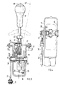
- FIGS. 2 and 3 The structural design of the switching device is shown in FIGS. 2 and 3.
- the first shift gate 2 and the second shift gate 7, which run in the longitudinal direction of the motor vehicle, and the transverse gate 6 are designed as backdrops for the selector lever 1 in a cover plate 13.
- the cover plate 13 is screwed onto a pot-shaped lower part 14, the walls of which are stiffened by ribs are.
- the cover plate 13 and the lower part 14 together form a hollow frame 17 which is fastened to the body of the motor vehicle.
- the lower part 14 is trapezoidal in longitudinal section (FIG. 2) and rectangular in cross section (FIG. 3).
- the part of the selector lever 1 protruding into the hollow frame 17 is connected to a universal joint 18, about the two transverse bearing pins 19 and 20 of which the selector lever 1 can be pivoted.
- the upper bearing pin 19 is mounted in the two side walls 15 and 16 of the lower part 14.
- the selector lever for executing the selector positions P, R, N, D, 3, 2, 1 can be swiveled around it.
- a pivot angle of a total of 34.6 ° in the opposite direction, a pivot angle of 28.2 ° is provided from the middle selector position D in the direction of travel of the motor vehicle.
- an articulated frame 23 is connected to it, which is pivoted when the selector positions are carried out.
- the bearing pin 20 is mounted in the articulated frame 13 below the bearing pin 19, about which the selector lever 1 can be pivoted when switching from the first shift gate 2 to the second shift gate 7.
- the swivel angle required for this is approx. 10 °.
- the switch positions of the selector lever are locked by a spring catch 24 acting on the underside of the selector lever 1 and fastened to the articulated frame 23.
- a pivoting of the selector lever in the second shift gate 7 of approximately 5 ° is sufficient to make the plus sensor 9 or the minus sensor 11 respond in the opposite direction and to trigger an upshift or a downshift by one gear on the transmission 3.
- the plus sensor 9 and the minus sensor 11 and the sensor 8 which detects the changeover are as Electromechanical microswitches formed and housed in a switch housing which is screwed onto the top plate 13.
- the actuating linkage 22 leading to the transmission consists of a fork head 31 articulated on the actuating lever 21 and a Bowden cable 32 attached to it, which can transmit tensile and compressive forces without buckling.
- the Bowden cable 32 is composed of a wire cable 29, which can transmit tensile and compressive forces, and a sheath 30 guiding it in the longitudinal direction.
- the sheath 30 is fixed in the bearing point 34, which is attached to the free end of a bracket 33 cast onto the lower part 14.
- the boom 33 is stiffened by ribs and forms a casting made of light metal with the lower part 14.
- the underside 35 of the boom 33 lies flush with the extension of the bottom 36 of the lower part 14.
- the selector lever 1 In order to place the handle 37 of the selector lever 1 at an ergonomically favorable location for the driver, given the position of the actuating linkage 22 and the mounting of the selector lever 1 in the hollow frame 17, the selector lever 1 is at an angle of approx. 15 in the upper region opposite to the direction of travel ° kinked. This makes it necessary to make the connecting element flexurally elastic from an unlocking button 38 which is guided longitudinally in the handle 37 to a locking device 39 for the respective gear selection position. At the same time, the connecting link must be able to transmit compressive forces without buckling. Both requirements can be met with a special Bowden cable 40 that can be subjected to pressure, the wire rope 41 of which is connected to the unlocking button 38 at the top and to the locking device 39 at the bottom.
Landscapes
- Engineering & Computer Science (AREA)
- Mechanical Engineering (AREA)
- General Engineering & Computer Science (AREA)
- Chemical & Material Sciences (AREA)
- Combustion & Propulsion (AREA)
- Transportation (AREA)
- Arrangement Or Mounting Of Control Devices For Change-Speed Gearing (AREA)
- Control Of Transmission Device (AREA)
- Gear-Shifting Mechanisms (AREA)
Claims (8)
- Dispositif de changement de vitesse pour une transmission automatique de véhicule commandée par une unité de commande électronique, comprenant un levier de sélection au moyen duquel, en le faisant pivoter, on peut sélectionner à l'avance dans un premier canal de changement de vitesse les diverses vitesses à changement automatique, le levier de sélection pouvant être amené par l'intermédiaire d'un passage transversal dans un second canal de changement de vitesse qui est parallèle au premier, les vitesses de la transmission pouvant être changées manuellement en faisant pivoter le levier de sélection dans le second canal de changement de vitesse, caractérisé en ce que le levier de sélection (1) est monté dans un cadre creux (17) constitué par l'assemblage d'une partie inférieure (14) en forme de pot et coulée en métal léger et d'une plaque de recouvrement (13) fixée sur elle par le haut, la partie inférieure (14) étant de forme trapézoïdale en section longitudinale et rectangulaire en section transversale.
- Dispositif de changement de vitesse selon la revendication 1, caractérisé en ce qu'un bras (33) est monté sur le côté extérieur de la partie inférieure (14), ce bras comprenant à son extrémité libre un point d'appui (34) destiné à une timonerie d'actionnement (22) allant à la transmission du véhicule et pouvant être déplacée longitudinalement par le levier de sélection (1).
- Dispositif de changement de vitesse selon la revendication 2, caractérisé en ce que la partie inférieure (14) est coulée en métal léger d'un seul tenant avec le bras (33).
- Dispositif de changement de vitesse selon la revendication 3, caractérisé en ce que le bras (33) va en se réduisant sous une forme conique depuis la partie inférieure (14) jusqu'au point (34) et est rendue rigide par des nervures.
- Dispositif de changement de vitesse selon la revendication 3, caractérisé en ce que le côté inférieur (35) du bras (33) est raccordé directement au fond (36) de la partie inférieure (14) et en prolongement avec lui.
- Dispositif de changement de vitesse selon la revendication 2, caractérisé en ce que la timonerie d'actionnement (22) est constituée par une chape (31) et un câble Bowden (32) guidé longitudinalement dans le point d'appui (34) et pouvant être sollicité en traction et en pression.
- Dispositif de changement de vitesse selon la revendication 1, caractérisé en ce que le levier de sélection (1) est coudé dans sa partie supérieure dans le sens inverse à celui de la marche.
- Dispositif de changement de vitesse selon la revendication 7, caractérisé en ce qu'une tête de déverrouillage (38) pouvant se déplacer longitudinalement dans la poignée (37) du levier de sélection (1) est reliée à un dispositif de verrouillage (39) des positions de sélection individuelles au moyen d'un câble Bowden (30) pouvant être sollicité en pression et passant au centre du levier de sélection (1).
Applications Claiming Priority (2)
| Application Number | Priority Date | Filing Date | Title |
|---|---|---|---|
| DE3927922A DE3927922C2 (de) | 1988-03-10 | 1989-08-24 | Schaltvorrichtung für ein Kraftfahrzeuggetriebe |
| DE3927922 | 1989-08-24 |
Publications (2)
| Publication Number | Publication Date |
|---|---|
| EP0413932A1 EP0413932A1 (fr) | 1991-02-27 |
| EP0413932B1 true EP0413932B1 (fr) | 1993-05-12 |
Family
ID=6387755
Family Applications (1)
| Application Number | Title | Priority Date | Filing Date |
|---|---|---|---|
| EP90112324A Expired - Lifetime EP0413932B1 (fr) | 1989-08-24 | 1990-06-28 | Dispositif de changement de vitesse pour une transmission de véhicule |
Country Status (4)
| Country | Link |
|---|---|
| EP (1) | EP0413932B1 (fr) |
| JP (1) | JPH03103650A (fr) |
| DE (1) | DE59001427D1 (fr) |
| ES (1) | ES2040529T3 (fr) |
Cited By (1)
| Publication number | Priority date | Publication date | Assignee | Title |
|---|---|---|---|---|
| CN100391758C (zh) * | 2003-10-15 | 2008-06-04 | 株式会社渥美精栈 | 车辆用自动变速操作装置 |
Families Citing this family (5)
| Publication number | Priority date | Publication date | Assignee | Title |
|---|---|---|---|---|
| ES2115493B1 (es) * | 1995-02-20 | 1999-02-16 | Fico Triad Sa | Dispositivo de mando para cambio de velocidades mixto automatico/manual-electronico. |
| JP3558111B2 (ja) * | 1997-08-29 | 2004-08-25 | 富士機工株式会社 | 自動変速機操作装置 |
| DE19905627B4 (de) * | 1998-02-16 | 2008-09-25 | Luk Gs Verwaltungs Kg | Getriebe für ein Kraftfahrzeug mit einer Wähleinrichtung |
| CN102518791B (zh) * | 2011-12-22 | 2015-03-11 | 宁波富诚汽车饰件有限公司 | 一种手球装配的复式连接结构及连接方法 |
| CN113586700A (zh) * | 2021-07-23 | 2021-11-02 | 上海科世达-华阳汽车电器有限公司 | 一种换挡系统和车辆 |
Citations (1)
| Publication number | Priority date | Publication date | Assignee | Title |
|---|---|---|---|---|
| EP0413116A1 (fr) * | 1989-08-18 | 1991-02-20 | Dr.Ing.h.c. F. Porsche Aktiengesellschaft | Dispositif de changement de vitesse |
Family Cites Families (5)
| Publication number | Priority date | Publication date | Assignee | Title |
|---|---|---|---|---|
| US4442730A (en) * | 1981-08-31 | 1984-04-17 | Twin Disc, Incorporated | Vehicle transmission system and a single lever control device therefor |
| US4541300A (en) * | 1983-03-28 | 1985-09-17 | Gulf & Western Manufacturing Company | Manually operable gearshift mechanism |
| DE3714285A1 (de) * | 1987-04-29 | 1988-11-10 | Ford Werke Ag | Waehlhebelanordnung fuer ein kraftfahrzeug-automatik-getriebe |
| DE3905769A1 (de) * | 1988-03-01 | 1989-09-14 | Zahnradfabrik Friedrichshafen | Elektrischer fahrschalter |
| DE3807881A1 (de) * | 1988-03-10 | 1989-09-21 | Porsche Ag | Schaltvorrichtung fuer ein automatikgetriebe eines kraftfahrzeugs |
-
1990
- 1990-06-28 ES ES199090112324T patent/ES2040529T3/es not_active Expired - Lifetime
- 1990-06-28 DE DE9090112324T patent/DE59001427D1/de not_active Expired - Lifetime
- 1990-06-28 EP EP90112324A patent/EP0413932B1/fr not_active Expired - Lifetime
- 1990-08-24 JP JP2221451A patent/JPH03103650A/ja active Pending
Patent Citations (1)
| Publication number | Priority date | Publication date | Assignee | Title |
|---|---|---|---|---|
| EP0413116A1 (fr) * | 1989-08-18 | 1991-02-20 | Dr.Ing.h.c. F. Porsche Aktiengesellschaft | Dispositif de changement de vitesse |
Cited By (1)
| Publication number | Priority date | Publication date | Assignee | Title |
|---|---|---|---|---|
| CN100391758C (zh) * | 2003-10-15 | 2008-06-04 | 株式会社渥美精栈 | 车辆用自动变速操作装置 |
Also Published As
| Publication number | Publication date |
|---|---|
| JPH03103650A (ja) | 1991-04-30 |
| ES2040529T3 (es) | 1993-10-16 |
| DE59001427D1 (de) | 1993-06-17 |
| EP0413932A1 (fr) | 1991-02-27 |
Similar Documents
| Publication | Publication Date | Title |
|---|---|---|
| DE3927922C2 (de) | Schaltvorrichtung für ein Kraftfahrzeuggetriebe | |
| EP0331797B2 (fr) | Dispositif de changement de vitesse pour une transmission automatique d'une automobile | |
| DE4005588C2 (de) | Schaltvorrichtung für ein automatisches Getriebe | |
| DE60200771T2 (de) | Elektrisch gesteuerte Getriebe für die Steuerung eines Kettenräderwechselgetriebes eines Fahrrads | |
| DE19549437C2 (de) | Schaltvorrichtung für ein automatisches Getriebe eines Kraftfahrzeugs | |
| EP0476291B1 (fr) | Dispositif de sélection pour une boîte de changement de vitesses de véhicule automobile | |
| DE19546547C1 (de) | Schaltvorrichtung für ein Gangwechselgetriebe eines Kraftfahrzeuges | |
| DE102005062167B3 (de) | Schalthebel mit Betätigungseinrichtung für eine Rückwärtsgangsperre | |
| DE4324788A1 (de) | Kraftfahrzeug mit einer Betätigungseinrichtung am Lenkrad | |
| DE3824296C2 (fr) | ||
| DE10259718A1 (de) | Schalthebelvorrichtung eines Automatikgetriebes zum Ermöglichen eines Handmodusbetriebs | |
| EP0052794B1 (fr) | Dispositif de commande pour la transmission d'un véhicule utilitaire | |
| EP0699853B1 (fr) | Tringlerie de sélection des vitesses pour boîte de vitesse d'un véhicule | |
| DE3216688C2 (de) | Abstützvorrichtung für einen am Boden angeordneten Getriebeschalthebel eines Kraftfahrzeuges | |
| EP0413932B1 (fr) | Dispositif de changement de vitesse pour une transmission de véhicule | |
| DE19633948A1 (de) | Wähleinrichtung für ein Automatikgetriebe eines Kraftfahrzeugs | |
| DE4231248C2 (de) | Gangschalteinrichtung für ein Kraftfahrzeug | |
| DE19754250B4 (de) | Betätigungsvorrichtung zur Anwahl von Fahrstufen und zur manuellen Schaltung von Übersetzungsverhältnissen eines Automatikgetriebes | |
| DE3337930A1 (de) | Waehlschalter in einer schaltsteuerung fuer automatgetriebe | |
| EP1181469B1 (fr) | Dispositif de changement de vitesses pour une boite automatique d'un vehicule automobile | |
| EP0413115A1 (fr) | Dispositif de changement de vitesse | |
| DE60103539T2 (de) | Unter dem lenkrad angebrachte steuerung für automatisiertes getriebe | |
| DE3717674A1 (de) | Schaltsteuereinrichtung eines kraftfahrzeugs mit automatischem getriebe | |
| EP0774602B1 (fr) | Levier de commande de boíte de vitesse pour véhicules automobiles | |
| DE19754247B4 (de) | Betätigungsvorrichtung von Übersetungsverhältnissen eines Automatikgetriebes |
Legal Events
| Date | Code | Title | Description |
|---|---|---|---|
| PUAI | Public reference made under article 153(3) epc to a published international application that has entered the european phase |
Free format text: ORIGINAL CODE: 0009012 |
|
| AK | Designated contracting states |
Kind code of ref document: A1 Designated state(s): DE ES FR GB IT NL SE |
|
| 17P | Request for examination filed |
Effective date: 19910628 |
|
| 17Q | First examination report despatched |
Effective date: 19920525 |
|
| GRAA | (expected) grant |
Free format text: ORIGINAL CODE: 0009210 |
|
| AK | Designated contracting states |
Kind code of ref document: B1 Designated state(s): DE ES FR GB IT NL SE |
|
| ITF | It: translation for a ep patent filed | ||
| REF | Corresponds to: |
Ref document number: 59001427 Country of ref document: DE Date of ref document: 19930617 |
|
| ET | Fr: translation filed | ||
| GBT | Gb: translation of ep patent filed (gb section 77(6)(a)/1977) |
Effective date: 19930709 |
|
| REG | Reference to a national code |
Ref country code: ES Ref legal event code: FG2A Ref document number: 2040529 Country of ref document: ES Kind code of ref document: T3 |
|
| EAL | Se: european patent in force in sweden |
Ref document number: 90112324.0 |
|
| PGFP | Annual fee paid to national office [announced via postgrant information from national office to epo] |
Ref country code: NL Payment date: 20000630 Year of fee payment: 11 |
|
| PG25 | Lapsed in a contracting state [announced via postgrant information from national office to epo] |
Ref country code: NL Free format text: LAPSE BECAUSE OF NON-PAYMENT OF DUE FEES Effective date: 20020101 |
|
| REG | Reference to a national code |
Ref country code: GB Ref legal event code: IF02 |
|
| NLV4 | Nl: lapsed or anulled due to non-payment of the annual fee |
Effective date: 20020101 |
|
| REG | Reference to a national code |
Ref country code: FR Ref legal event code: TP |
|
| PGFP | Annual fee paid to national office [announced via postgrant information from national office to epo] |
Ref country code: ES Payment date: 20090623 Year of fee payment: 20 |
|
| PGFP | Annual fee paid to national office [announced via postgrant information from national office to epo] |
Ref country code: IT Payment date: 20090625 Year of fee payment: 20 Ref country code: SE Payment date: 20090612 Year of fee payment: 20 Ref country code: FR Payment date: 20090615 Year of fee payment: 20 |
|
| REG | Reference to a national code |
Ref country code: FR Ref legal event code: CD |
|
| PGFP | Annual fee paid to national office [announced via postgrant information from national office to epo] |
Ref country code: GB Payment date: 20090618 Year of fee payment: 20 Ref country code: DE Payment date: 20090602 Year of fee payment: 20 |
|
| REG | Reference to a national code |
Ref country code: GB Ref legal event code: PE20 Expiry date: 20100627 |
|
| EUG | Se: european patent has lapsed | ||
| REG | Reference to a national code |
Ref country code: ES Ref legal event code: FD2A Effective date: 20100629 |
|
| PG25 | Lapsed in a contracting state [announced via postgrant information from national office to epo] |
Ref country code: ES Free format text: LAPSE BECAUSE OF EXPIRATION OF PROTECTION Effective date: 20100629 |
|
| PG25 | Lapsed in a contracting state [announced via postgrant information from national office to epo] |
Ref country code: GB Free format text: LAPSE BECAUSE OF EXPIRATION OF PROTECTION Effective date: 20100627 |
|
| PG25 | Lapsed in a contracting state [announced via postgrant information from national office to epo] |
Ref country code: DE Free format text: LAPSE BECAUSE OF EXPIRATION OF PROTECTION Effective date: 20100628 |
|
| PLBE | No opposition filed within time limit |
Free format text: ORIGINAL CODE: 0009261 |
|
| STAA | Information on the status of an ep patent application or granted ep patent |
Free format text: STATUS: NO OPPOSITION FILED WITHIN TIME LIMIT |