EP0412834B1 - Material supplying apparatus for a powder moulding machine - Google Patents
Material supplying apparatus for a powder moulding machine Download PDFInfo
- Publication number
- EP0412834B1 EP0412834B1 EP90308814A EP90308814A EP0412834B1 EP 0412834 B1 EP0412834 B1 EP 0412834B1 EP 90308814 A EP90308814 A EP 90308814A EP 90308814 A EP90308814 A EP 90308814A EP 0412834 B1 EP0412834 B1 EP 0412834B1
- Authority
- EP
- European Patent Office
- Prior art keywords
- die
- supplying apparatus
- inputting device
- weight
- weight scaling
- Prior art date
- Legal status (The legal status is an assumption and is not a legal conclusion. Google has not performed a legal analysis and makes no representation as to the accuracy of the status listed.)
- Expired - Lifetime
Links
Images

Classifications
-
- B—PERFORMING OPERATIONS; TRANSPORTING
- B28—WORKING CEMENT, CLAY, OR STONE
- B28B—SHAPING CLAY OR OTHER CERAMIC COMPOSITIONS; SHAPING SLAG; SHAPING MIXTURES CONTAINING CEMENTITIOUS MATERIAL, e.g. PLASTER
- B28B13/00—Feeding the unshaped material to moulds or apparatus for producing shaped articles; Discharging shaped articles from such moulds or apparatus
- B28B13/02—Feeding the unshaped material to moulds or apparatus for producing shaped articles
-
- B—PERFORMING OPERATIONS; TRANSPORTING
- B29—WORKING OF PLASTICS; WORKING OF SUBSTANCES IN A PLASTIC STATE IN GENERAL
- B29C—SHAPING OR JOINING OF PLASTICS; SHAPING OF MATERIAL IN A PLASTIC STATE, NOT OTHERWISE PROVIDED FOR; AFTER-TREATMENT OF THE SHAPED PRODUCTS, e.g. REPAIRING
- B29C31/00—Handling, e.g. feeding of the material to be shaped, storage of plastics material before moulding; Automation, i.e. automated handling lines in plastics processing plants, e.g. using manipulators or robots
- B29C31/04—Feeding of the material to be moulded, e.g. into a mould cavity
- B29C31/06—Feeding of the material to be moulded, e.g. into a mould cavity in measured doses, e.g. by weighting
- B29C31/065—Feeding of the material to be moulded, e.g. into a mould cavity in measured doses, e.g. by weighting using volumetric measuring chambers moving between a charging station and a discharge station
- B29C31/066—Feeding of the material to be moulded, e.g. into a mould cavity in measured doses, e.g. by weighting using volumetric measuring chambers moving between a charging station and a discharge station using feed frames, e.g. for dry material
-
- B—PERFORMING OPERATIONS; TRANSPORTING
- B30—PRESSES
- B30B—PRESSES IN GENERAL
- B30B15/00—Details of, or accessories for, presses; Auxiliary measures in connection with pressing
- B30B15/30—Feeding material to presses
- B30B15/302—Feeding material in particulate or plastic state to moulding presses
- B30B15/304—Feeding material in particulate or plastic state to moulding presses by using feed frames or shoes with relative movement with regard to the mould or moulds
Abstract
Description
- The present invention relates to a weight scaling type material supplying apparatus for a powder moulding machine for moulding, for instance, firebricks.
- Methods of feeding a material into a moulding machine may be divided into two types, that is, weight scaling and volume measuring types.
- A weight scaling type feeder comprising a
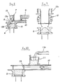
scaling device 12 having aload cell 12a (shown in Fig. 9) is usually used with a pressing machine in a so-called "die movement truck system", in which a die 5 is moved by a truck. An example of a block moulding press using a weight scaling device can be found in FR-A-219564 which discloses a weighing container which is lowered over a moveable charger frame to transfer the material once it has been weighed, without material loss. The charger frame is then moved over the the die to deposit the material for pressing. - A volume measuring type feeder comprising a conveyer 11a, a hopper 11, a
material inputting device 7A, and a cylinder 10 (see Fig. 10) is usually used with a pressing machine in a so-called "die floating type central moulding system", in which the die 5 is elevated by a floating cylinder 16 (Fig. 1). - The superiority and/or inferiority of the weight scaling apparatus compared with the volume measuring apparatus has yet to be decided, because both have advantages and disadvantages, and also because the moulding conditions can fluctuate largely depending on grain size, the composition of the powder material, and the kind of binder used, etc.
- With respect to the above, the applicant has already proposed a volume measuring type of material supplying apparatus in which the possibility of the material separating into fine and coarse powder, or forming large clumps, can be reduced for any material, as can measuring errors.
- In recent years, however, error conditions (tolerances) have become very severe and critical. For instance, in the case of a brick having a weight of 5 kg, the error (tolerance) in its thickness must be within a range of ± 0.2 mm and this value must be measured on the basis of a state in which the material is most densely packed.
- In the conventional volume measuring technique, the weight of the firebrick can vary by more than 20 g, and, as the thickness of the brick is proportional to its weight, it is therefore very difficult to fulfil the above required thickness tolerances.
- Even when the accuracy of the volume measuring technique is raised, there is a limitation, in that, the thickness of the bricks produced lie within a range of ± 0.5 to 1%. In other words, in the case of a brick weight of 5 kg, the error of its thickness dimension lies within a range of from 0.5 to 1 mm which is outside the tolerance levels detailed above. In addition, the above-mentioned conditions must be fulfilled in a state in which the material is most densely packed.
- Therefore, in a case where a volume measuring type supplying apparatus is merely used, the above-mentioned severe and critical conditions and tolerances cannot be fulfilled. In other words, a weight scaling type supplying apparatus is needed in such a case.
- In the case of forming a relatively small brick, and from the viewpoint of productivity, such a brick must be moulded efficiently. For this purpose, even if the
scaling device 12 comprising theload cell 12a shown in Fig. 9 is applied to a volume type charger attached to, for example, the central moulding type pressing machine, a distance L (shown in Fig. 1) between the pressing devices, that is, an idle stroke, needs to be largely increased. - In consideration of the above-mentioned circumstances, there have conventionally been demanded techniques in which measuring errors in the weight can be made as small as possible, separation of fine and coarse powder and the formation of large clumps of material can be prevented, a drop height between an outlet of the material supply means and a die can be made as short as possible, a movement surface which comes into contact with the material can be made as small as possible (since a hard material such as a grinding material or the like which can damage the surface is frequently used as the moulded material), the amount of loss of material can be minimized, and a tapered surface can be preliminarily formed on a surface of the supplied material (because a moulded brick generally requires a tapered surface). In order to improve the productivity, it is desirable to utilize a pressing machine of the so-called "die floating central moulding type".
- The present invention aims to fulfil the above-mentioned requirements and it is an object of the invention to provide a scaling type material supplying apparatus for a powder moulding machine in which weight errors (measuring errors in weight) of products can be reduced and the productivity can be improved.
- According to the present invention, a weight scaling type material supplying apparatus for a powder moulding machine is provided, which comprises a weight scaling device having a material weighing means, a charger frame movable over a press table, a material inputting device provided on said charger frame for receiving a predetermined weight of material from said scaling device;
characterised in that said apparatus includes mixing means for mixing said material supplied to said material inputting device. - Thus, the invention provides an inputting device in which the accuracy of the weight of material input is high due to the use of a load cell and the composition of the material is made uniform by the mixing means. Preferably, the mixing means comprises a set of rotary blades attached to a vertical shaft of said apparatus for movement into and out of said material inputting device.
- Further preferably, a shutter plate is provided between said material inputting device and said press table, and is actuable to open and close an outlet of said material inputting device when said inputting device is moved over a die of said moulding machine. By such an arrangement the material only contacts a small area of the shutter plate rather than a large area of the press table, and loss of material is kept to a minimum.
- The shutter plate may be actuated by a piston and cylinder mounted between the shutter plate and the charger frame. Also, in order to ensure that a minimum of material is lost, a seal may be provided around the periphery of the shutter between the shutter and the press table.
- Still further, a tapered surface forming means is preferably provided which forms a tapered surface on the material when the material has been supplied to the die from the inputting device and the charger frame has begun to move back from the die.
- The tapered surface forming means may be mounted on the side of the inputting device closest to said die, and may comprise a horizontal rod mounted perpendicularly to the direction of movement of said charger frame on a piston, said rod being moved downwardly a set distance into said die when said charger frame begins to move back from said die, and being gradually withdrawn as said charger frame continues its movement so that a tapered surface is formed on the top surface of said material.
- When a material is input (supplied) to the die, it is preferable to construct the apparatus in such a manner that a lower ram is relatively elevated in relation to the die in order to reduce a drop height of said material (inputting drop height), and thereafter, the lower ram is relatively lowered in relation to the die, so that the raw material is completely input (supplied) into the die.
- According to the preferred scaling type material supplying apparatus of the present invention, after a material is supplied from the scaling device to the material inputting device, the material inputting device is moved forward by, for example, a piston and cylinder and stopped at a position just below the rotary blades. The material is then stirred by the rotary blades. Thus, the separation of the material into coarse and fine powder and the forming of large clumps of material is prevented, and the material is uniformly mixed. After this, the material inputting device is moved further forward to a position over the die, and the lower ram is relatively elevated in relation to the die. Then, the second cylinder, between the shutter and charger frame, is extended, causing the shutter frame to move backwardly and open the material inputting device, thereby inputting the material into the die at a small drop height. The lower ram is then lowered in relation to the die so that the material is completely input into the die. After this, the material inputting device is moved back from the die. The tapering bar is extended into the die at the start of this backward movement, and is gradually retracted upwards during the backward movement. A tapered surface which is upwardly inclined toward the backward direction is thus formed by the bar on the upper surface of the material in the die.
- An embodiment of the present invention will now be described, by way of example only, with reference to the accompanying drawings, in which
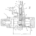
- Fig. 1 is a side sectional view of an embodiment of the present invention,
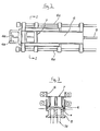
- Fig. 2 is a plan view of the shutter plate and charger frame of Fig. 1,
- Fig. 3 is a cross-sectional view taken along line I-I of Fig. 2 which also shows a die and lower ram of the moulding apparatus,
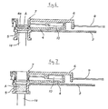
- Fig. 4 to 8 are side-sectional views showing relevant parts of the apparatus in various operational stages, and
- Fig. 9 and 10 show conventional apparatuses of the weight scaling and the volume measuring types, respectively.
- Referring to Figs. 1 to 3, reference numeral 1 denotes a powder moulding machine of the die floating central moulding type for simultaneously moulding two bricks in parallel by a well-known technique.
- The die 5 is arranged so that it can be freely elevated by means of floating
cylinders 16. A horizontal press table 2 is attached to the die 5. Ashutter plate 4 having adust seal 3 around its periphery is provided at a small height α of, for instance, 0.1 mm above the upper surface of the table 2 (see Fig. 3) so that theshutter plate 4 is slidable in the front/back directions (right/left directions in the drawings) of the apparatus. A pair ofopening portions 4a, are formed in theshutter plate 4, and amaterial inputting device 7, which is in slidable contact with theshutter plate 4 through adust seal 8, is provided so that it may face theopening portions 4a. A left end portion of acharger frame 6 which extends in the horizontal right direction is coupled to the rawmaterial inputting device 7. A right end portion of thecharger frame 6 is coupled to a hydraulic or pneumaticfirst cylinder 9. A hydraulic or pneumaticsecond cylinder 10 is interposed between thecharge frame 6 and theshutter plate 4. A tapered surface forming cylinder 13 (as a tapered surface forming means) is provided on the front, die side, portion of thematerial inputting device 7. Ahorizontal bar 13a which extends perpendicularly to the direction of movement of thecharger frame 6 is provided on thecylinder 13. -
Reference numerals 6a in Fig. 2 denote guide bars for guiding theshutter plate 4 and thecharger frame 6. In place of theguide bars 6a, a box-type guide could also be used, or thecharger frame 6 could be attached to a roller type truck which rides over theshutter plate 4. - The
scaling device 12 including theload cell 12a is arranged over thecharger frame 6. A conveyer 11a for measuring and transporting material stored in the hopper 11 to thescaling device 12 is arranged over thescaling device 12, and, as shown in Fig. 4, a vertical rotary shaftstirring blade device 14, which is driven by a motor and is elevated by a hydraulic orpneumatic cylinder 15, is arranged between thescaling device 12 and thedie 5. The inner surface of the hopper 11 has a structure such that none of the powder material deposits on it. - Upon operation, a material A, which is measured and supplied from the material hopper 11 and conveyed by the conveyer 11a, is scaled to a value having an accuracy of within a range of, for instance, ± 10 g, by means of the
load cell 12a of thescaling device 12. - Next, as shown in Fig. 4, the
cylinder 9 is contracted into a state in which thecylinder 10 is also contracted. Thus, thecharger frame 6 is moved backwardly, and thematerial inputting device 7 faces thescaling device 12. Then, theshutter 12b is opened and the material A is supplied to thematerial inputting device 7. - Next, the
cylinder 9 is extended, and thematerial inputting device 7 is moved forward from the position shown in Fig. 4 until it stops at a position under theblade device 14. Then, thecylinder 15 is extended, theblade device 14 descends, the material A is stirred, and the separation of the material into fine and coarse powder and the formation of large clumps of material is prevented, thereby uniformly mixing the material A. - When the
cylinder 15 is contracted and theblade device 14 is lifted up to its original position, thecylinder 9 is further extended, thecharger frame 6 is forwardly moved, and thematerial inputting device 7 is stopped in a position over thedie 5 as shown in Fig.5. - Subsequently, as shown in Fig. 6, the floating
cylinders 16 are contracted, thedie 5 is lowered, and a lower ram 1a of the powder moulding machine 1 is lifted up in relation to thedie 5 until it reaches a position near theshutter plate 4. Then, thecylinder 10 is extended, theshutter plate 4 is moved back, the openingportions 4a face thematerial inputting device 7, and the material A is input (supplied) to thedie 5. - Therefore, the drop height upon input of the material A is very small, and an area of the
frame 6 with which the material A comes into contact (the movement contact area of the material A) is small. In this embodiment, the movement contact area of the material A is an area of theshutter frame 4 which faces thematerial inputting device 7. Thus, abrasion of the machine's components by the material A, and spill of the material A, is minimized. - Next, as shown in Fig. 7, the floating
cylinders 16 are extended, thedie 5 is raised, the lower ram 1a descends in relation to thedie 5, and the material A is completely supplied into thedie 5. - From this position, the
cylinder 9 is contracted and thecharger frame 6 starts to move back from thedie 5, as shown in Fig. 8. At this point, thecylinder 13 is extended, and thehorizontal bar 13a descends to aposition 13b indicated by the broken line in Fig.8. The piston ofcylinder 13 is sequentially retracted during the backward movement of thecharger frame 6, and a tapered surface B which is upwardly backwardly inclined is formed on the surface of the material A in thedie 5 by thehorizontal bar 13a. - Since the present invention has been constructed as described above, the scaling accuracy is improved, the spill of the material is minimized, the material in the material inputting device is uniformly mixed, the material is input (supplied) into the die at a minimum drop height, the weight tolerance error of the products can be minimized, clean surroundings are obtained, and productivity can be improved.
Claims (10)
- Weight scaling material supplying apparatus for a powder moulding machine (1) comprising a weight scaling device (12) having a material weighing means, a charger frame (6) movable over a press table (2), a material inputting device (7) provided on said charger frame for receiving a predetermined weight of material from said scaling device;
characterised in that said apparatus includes mixing means (14) for mixing said material supplied to said material inputting device. - Weight scaling material supplying apparatus according to claim 1, wherein said mixing means (14) comprises a set of rotary blades attached to a vertical shaft of said apparatus for movement into and out of said material inputting device.
- Weight scaling material supplying apparatus according to claim 1 or 2, wherein a shutter plate (4) is provided between said material inputting device (7) and said press table (2), and is actuable to open and close an outlet of said material inputting device when said inputting device is moved over a die (5) of said moulding machine.
- Weight scaling material supplying apparatus according to claim 3, wherein said shutter plate (4) is actuated by a piston and cylinder (10) mounted between said shutter plate and said charger frame.
- Weight scaling material supplying apparatus according to claim 3 or 4, wherein a seal (3) is provided around the periphery of the shutter (4) between the shutter and the press table (2).
- Weight scaling material supplying apparatus according to any preceding claim, wherein a tapered surface forming means (13) is provided for forming a tapered surface on said material (A) after said material has been supplied to a die (5) of said moulding machine.
- Weight scaling material supplying apparatus according to claim 6, wherein said tapered surface forming means (13) is mounted on the side of said inputting device (7) closest to said die (5), and comprises a horizontal rod (13a) mounted perpendicularly to the direction of movement of said charger frame (6) on a piston, said rod being moved downwardly a set distance into said die when said charger frame begins to move back from said die, and being gradually withdrawn as said charger frame continues its movement so that a tapered surface is formed on the top surface of said material (A).
- Weight scaling material supplying apparatus according to any preceding claim, wherein said press table houses (2) said die (5) and is vertically movable on a cylinder (16), said press table being lowered with respect to a press ram of said moulding machine when said material (A) is applied to said die, so that the material only falls a short distance when being fed into said die, and when said material has been supplied to said die, said press table is raised with respect to said ram so that the material is completely input into said die.
- Weight scaling material supplying apparatus according to any preceding claim, wherein said charger frame (6) is moved by a cylinder (9).
- Weight scaling material supplying apparatus according to any preceding claim, wherein said material weighing means comprises a load cell (12a).
Priority Applications (1)
| Application Number | Priority Date | Filing Date | Title |
|---|---|---|---|
| AT90308814T ATE101557T1 (en) | 1989-08-10 | 1990-08-10 | FEED DEVICE OF POWDER MATERIAL FOR A MOLDING PRESS. |
Applications Claiming Priority (2)
| Application Number | Priority Date | Filing Date | Title |
|---|---|---|---|
| JP1205639A JPH0637047B2 (en) | 1989-08-10 | 1989-08-10 | Weighing type raw material supply device of powder molding machine |
| JP205639/89 | 1989-08-10 |
Publications (3)
| Publication Number | Publication Date |
|---|---|
| EP0412834A2 EP0412834A2 (en) | 1991-02-13 |
| EP0412834A3 EP0412834A3 (en) | 1991-09-11 |
| EP0412834B1 true EP0412834B1 (en) | 1994-02-16 |
Family
ID=16510224
Family Applications (1)
| Application Number | Title | Priority Date | Filing Date |
|---|---|---|---|
| EP90308814A Expired - Lifetime EP0412834B1 (en) | 1989-08-10 | 1990-08-10 | Material supplying apparatus for a powder moulding machine |
Country Status (11)
| Country | Link |
|---|---|
| US (1) | US5074774A (en) |
| EP (1) | EP0412834B1 (en) |
| JP (1) | JPH0637047B2 (en) |
| KR (1) | KR910004317A (en) |
| CN (1) | CN1023198C (en) |
| AT (1) | ATE101557T1 (en) |
| AU (1) | AU624975B2 (en) |
| BR (1) | BR9003870A (en) |
| DE (1) | DE69006658T2 (en) |
| ES (1) | ES2051474T3 (en) |
| MX (1) | MX170786B (en) |
Families Citing this family (45)
| Publication number | Priority date | Publication date | Assignee | Title |
|---|---|---|---|---|
| US5284431A (en) * | 1990-08-28 | 1994-02-08 | Jsp Corporation | Filling apparatus for filling foamed particles of a thermoplastic resin into a mold |
| US5672363A (en) * | 1990-11-30 | 1997-09-30 | Intermetallics Co., Ltd. | Production apparatus for making green compact |
| KR0180557B1 (en) * | 1990-12-26 | 1999-03-20 | 후까이 히로도시 | Brick press |
| IT1272414B (en) * | 1993-04-28 | 1997-06-23 | Robosint Srl | AUTOMATIC WEIGHING AND COLD COMPACTING OF DIAMOND POWDERS |
| AU646380B3 (en) * | 1993-11-11 | 1994-02-17 | Fastidia Pty Ltd | Distributing low slump concrete |
| US5885625A (en) * | 1996-06-14 | 1999-03-23 | Materials Innovation, Inc. | Pressurized feed shoe apparatus for precompacting powdered materials |
| US5897826A (en) * | 1996-06-14 | 1999-04-27 | Materials Innovation, Inc. | Pulsed pressurized powder feed system and method for uniform particulate material delivery |
| US5885496A (en) * | 1996-08-29 | 1999-03-23 | Materials Innovation, Inc. | Pressurized feedshoe apparatus and method for precompacting powdered materials |
| WO2001049470A1 (en) * | 1998-07-21 | 2001-07-12 | Kabushikikaisha Mitsuishi Fukai Tekkosho | Raw material feeder for firebrick making machines |
| DE69931133T2 (en) * | 1998-12-28 | 2006-11-23 | Neomax Co., Ltd., Osaka | Method and apparatus for introducing rare earth alloy powder |
| EP1016947A3 (en) | 1998-12-31 | 2006-04-26 | Texas Instruments Incorporated | Portable electronic equipment key |
| US6302675B1 (en) * | 1999-03-24 | 2001-10-16 | Foxfire, Llc | Pressed earth block machine |
| AU6749500A (en) * | 1999-07-29 | 2001-02-19 | Materials Innovation Inc. | Hydraulic powder press |
| US6676862B2 (en) * | 1999-09-15 | 2004-01-13 | Advanced Building Systems, Inc. | Method for forming lightweight concrete block |
| US6312629B1 (en) * | 2000-02-04 | 2001-11-06 | The United States Of America As Represented By The Secretary Of The Navy | Apparatus and method for pressing powders |
| KR20030097202A (en) * | 2002-06-20 | 2003-12-31 | 새한공업(주) | Nails with powered screws |
| US20050029690A1 (en) * | 2003-08-08 | 2005-02-10 | George Burlow | Method and apparatus for manufacturing compressed earthen blocks |
| ITUD20030170A1 (en) * | 2003-08-20 | 2005-02-21 | Planitec Srl | MANIPULATOR DEVICE FOR CONTAINERS IN MOLDING SYSTEMS AND RELATIVE HANDLING METHOD. |
| NL1025045C2 (en) * | 2003-12-17 | 2005-06-20 | Mason Machines B V | Apparatus for compacting building material, e.g. mortar, and comprises at least one filling unit formed from at least one storage buffer |
| US8419409B2 (en) * | 2006-12-21 | 2013-04-16 | D.I.T. Equipments Inc. | Molding station with deformable mold and method |
| JP5192172B2 (en) * | 2007-04-18 | 2013-05-08 | 株式会社菊水製作所 | Control device for powder compression molding machine |
| ITUD20070130A1 (en) * | 2007-07-23 | 2009-01-24 | C M E Spa Sa | MACHINE AND PROCEDURE FOR THE PRODUCTION OF STRUCTURAL ELEMENTS FOR BUILDING IN CEMENTITIAL MATERIALS WITH ONE OR MORE INSERTS IN POLYMERIC MATERIAL |
| KR100883272B1 (en) * | 2007-08-03 | 2009-02-11 | 고등기술연구원연구조합 | Powder mixing apparatus using a quantitative transfer conveyer |
| CN101200122B (en) * | 2007-08-27 | 2012-12-12 | 邵中民 | Feeding device for powder forming machine |
| CN102049875B (en) * | 2009-11-10 | 2014-08-27 | 北京宝粒特木煤机械制造有限公司 | Wood coal briquetting machine |
| CN101979245B (en) * | 2010-10-14 | 2014-06-04 | 西安交通大学 | Single punch tablet press |
| CN102152426A (en) * | 2011-04-26 | 2011-08-17 | 太仓市立新电器塑料有限公司 | Pelleting extruder |
| CN102275334A (en) * | 2011-08-19 | 2011-12-14 | 天津市天锻压力机有限公司 | Powder feeding device for powder hydraulic machine |
| CN102431199A (en) * | 2011-11-24 | 2012-05-02 | 淄博皓译工贸有限公司 | Special pressing machine for insulation boards |
| CN102416470B (en) * | 2011-12-12 | 2013-07-31 | 上海平野磁气有限公司 | Quantitative feeding device for full-automatic magnetic powder molding press |
| CN102513534B (en) * | 2011-12-12 | 2013-07-31 | 上海平野磁气有限公司 | Quantitative feeding device of fully-automatic magnetic powder forming press |
| CN102941685B (en) * | 2012-10-30 | 2014-10-22 | 宁波百琪达自动化设备有限公司 | Full-automatic seal forming mold press |
| CN103963152A (en) * | 2013-01-28 | 2014-08-06 | 郑州金鑫机械制造有限公司 | Intelligent brick feeding and discharging machine |
| CN103935070B (en) * | 2014-05-05 | 2017-06-16 | 朱锦忠 | The guide tracked feeding device of autoamtic powder press |
| KR101534125B1 (en) * | 2015-02-11 | 2015-07-07 | 주식회사 비욘텍 | Forming device of brake pad |
| US11278910B2 (en) * | 2015-05-17 | 2022-03-22 | Creator, Inc. | Systems and method for grinding a food product |
| CN105171889A (en) * | 2015-05-22 | 2015-12-23 | 中国装饰股份有限公司 | Pressing device for floors |
| CN105109082A (en) * | 2015-06-30 | 2015-12-02 | 赖海荣 | Copper cuttings caking machine |
| WO2017005555A1 (en) * | 2015-07-06 | 2017-01-12 | Basf Se | Production station and production arrangement with a table framework for producing bonded layered beds of magnetocaloric material and a method of producing bonded layered beds of magnetocaloric material |
| CN105252801A (en) * | 2015-10-27 | 2016-01-20 | 苏州市海岸钛业股份有限公司 | Titanium chip recycling and ingot pressing device |
| US11472062B2 (en) * | 2018-01-10 | 2022-10-18 | Louis HEBERT | Filler and demolding system for a non-linear molded product |
| CN108858905B (en) * | 2018-05-16 | 2021-07-02 | 甘春勇 | EPS particle feeding device and control method thereof |
| US11141880B2 (en) * | 2018-10-10 | 2021-10-12 | Charles Jerome Maffett | Automated method and system for forming prefabricated vertical wall construction units |
| CN109332683B (en) * | 2018-11-15 | 2023-12-08 | 广东鑫信智能装备有限公司 | Adjustable powder metering and feeding device |
| CN111906895B (en) * | 2020-07-14 | 2021-05-14 | 浙江嘉吉石化工程有限公司 | Automatic production equipment and process for high-strength high-purity corundum bricks |
Family Cites Families (17)
| Publication number | Priority date | Publication date | Assignee | Title |
|---|---|---|---|---|
| US759259A (en) * | 1902-11-29 | 1904-05-10 | Harry J Flood | Attachment for machines for compressing material into form. |
| US1568832A (en) * | 1922-09-12 | 1926-01-05 | Harrison John Arthur | Apparatus for the manufacture of composition building sheets or slabs |
| US1733706A (en) * | 1928-03-29 | 1929-10-29 | Widin Edgar | Machine for making concrete blocks |
| US2270829A (en) * | 1939-04-07 | 1942-01-20 | Harry A Wellnitz | Machine for forming building blocks |
| GB736551A (en) * | 1953-04-24 | 1955-09-07 | British Industrial Plastics | Loading device for moulding presses |
| NL249868A (en) * | 1959-06-02 | |||
| US3166814A (en) * | 1963-05-28 | 1965-01-26 | Harbison Walker Refractories | Brickmaking |
| US3407458A (en) * | 1965-10-23 | 1968-10-29 | A R Ind Inc | Apparatus for producing pre-cast concrete members including reinforcing rod holders pivotally mounted on mold box |
| US3499069A (en) * | 1966-08-18 | 1970-03-03 | Struthers Scient & Intern Corp | Method of making bricks |
| US3604075A (en) * | 1969-01-27 | 1971-09-14 | Stearns Mfg Co | Density control system for block-making apparatus |
| US3811808A (en) * | 1971-02-22 | 1974-05-21 | Dresser Ind | Weighed charge system for a brick press |
| CH547697A (en) * | 1972-08-03 | 1974-04-11 | Von Roll Ag | PRESS FOR THE PRODUCTION OF BLOCKS, IN PARTICULAR BLOCK ELECTRODES. |
| DE2605514B2 (en) * | 1976-02-12 | 1978-09-14 | Dorstener Maschinenfabrik Ag, 4270 Dorsten | Press system for the production of conical stones |
| JPS6351107A (en) * | 1986-08-21 | 1988-03-04 | 株式会社 後藤鉄工所 | Raw material filler for multilayer tile |
| DE8714762U1 (en) * | 1987-11-06 | 1988-02-11 | Laeis Gmbh, 5500 Trier, De | |
| JPH01123703A (en) * | 1987-11-09 | 1989-05-16 | Mitsuishi Fukai Tekkosho:Kk | Raw material feeding device of powder molder |
| FR2624485B1 (en) * | 1987-12-11 | 1992-04-24 | Commissariat Energie Atomique | PACK OF POWDER AND GRANULES FEEDING AVAILABLE, ESPECIALLY FOR A PELLET PRESS |
-
1989
- 1989-08-10 JP JP1205639A patent/JPH0637047B2/en not_active Expired - Lifetime
-
1990
- 1990-06-09 KR KR1019900008453A patent/KR910004317A/en active IP Right Grant
- 1990-07-12 AU AU58950/90A patent/AU624975B2/en not_active Ceased
- 1990-07-26 US US07/557,843 patent/US5074774A/en not_active Expired - Fee Related
- 1990-07-28 CN CN90106597A patent/CN1023198C/en not_active Expired - Fee Related
- 1990-08-08 BR BR909003870A patent/BR9003870A/en not_active IP Right Cessation
- 1990-08-09 MX MX021926A patent/MX170786B/en unknown
- 1990-08-10 DE DE69006658T patent/DE69006658T2/en not_active Expired - Fee Related
- 1990-08-10 EP EP90308814A patent/EP0412834B1/en not_active Expired - Lifetime
- 1990-08-10 AT AT90308814T patent/ATE101557T1/en not_active IP Right Cessation
- 1990-08-10 ES ES90308814T patent/ES2051474T3/en not_active Expired - Lifetime
Also Published As
| Publication number | Publication date |
|---|---|
| EP0412834A3 (en) | 1991-09-11 |
| ATE101557T1 (en) | 1994-03-15 |
| BR9003870A (en) | 1991-09-03 |
| DE69006658D1 (en) | 1994-03-24 |
| ES2051474T3 (en) | 1994-06-16 |
| MX170786B (en) | 1993-09-14 |
| KR910004317A (en) | 1991-03-28 |
| EP0412834A2 (en) | 1991-02-13 |
| AU5895090A (en) | 1991-02-14 |
| CN1023198C (en) | 1993-12-22 |
| CN1049475A (en) | 1991-02-27 |
| US5074774A (en) | 1991-12-24 |
| JPH0637047B2 (en) | 1994-05-18 |
| DE69006658T2 (en) | 1994-05-26 |
| JPH0369311A (en) | 1991-03-25 |
| AU624975B2 (en) | 1992-06-25 |
Similar Documents
| Publication | Publication Date | Title |
|---|---|---|
| EP0412834B1 (en) | Material supplying apparatus for a powder moulding machine | |
| US3277551A (en) | Concrete block molding machines | |
| US3127459A (en) | Process and apparatus for making perforated bricks | |
| CN109566790A (en) | A kind of tealeaves brick forming machine | |
| US3811808A (en) | Weighed charge system for a brick press | |
| CN102085690B (en) | Full-automatic concrete board die casting machine | |
| CN109319241B (en) | Automatic compression packing bagging machine with weighing hopper | |
| CN209409388U (en) | Waste material precompressed mechanism with weighing device | |
| EP0035568B1 (en) | Brick forming apparatus | |
| CN206703389U (en) | A kind of full-automatic compressing system of drum-type brake pad | |
| EP1433580A2 (en) | Method and apparatus for producing ceramic products | |
| US2893101A (en) | Brick press batch distributor | |
| CN210820137U (en) | Portable cloth pressed compact device | |
| US3553798A (en) | Apparatus for producing precast concrete members | |
| US3166814A (en) | Brickmaking | |
| CN211539117U (en) | Production equipment for counter weight blocks of cold rolling hot pressing elevator | |
| JP7154584B2 (en) | Dry cosmetic molding machine adopting block molding method | |
| JP2002086438A (en) | Equipment for supplying raw material to brick molding machine | |
| CN201895349U (en) | Full-automatic die casting machine for concrete plate | |
| CN217455035U (en) | Forming device is used in graphite product production | |
| CN217648581U (en) | Corundum brick apparatus for producing | |
| CN215202629U (en) | Automatic feeding machine for producing refractory materials | |
| JP2000326317A (en) | Stock feeding device | |
| CN219169616U (en) | Feeding mechanism of single-person operation press | |
| CN214266072U (en) | Fly ash brick's press forming device |
Legal Events
| Date | Code | Title | Description |
|---|---|---|---|
| PUAI | Public reference made under article 153(3) epc to a published international application that has entered the european phase |
Free format text: ORIGINAL CODE: 0009012 |
|
| AK | Designated contracting states |
Kind code of ref document: A2 Designated state(s): AT CH DE ES GB IT LI |
|
| PUAL | Search report despatched |
Free format text: ORIGINAL CODE: 0009013 |
|
| AK | Designated contracting states |
Kind code of ref document: A3 Designated state(s): AT CH DE ES GB IT LI |
|
| 17P | Request for examination filed |
Effective date: 19911106 |
|
| 17Q | First examination report despatched |
Effective date: 19921130 |
|
| RAP1 | Party data changed (applicant data changed or rights of an application transferred) |
Owner name: KABUSHIKI KAISHA MITSUISHI FUKAI TEKKOSHO |
|
| ITF | It: translation for a ep patent filed |
Owner name: BARZANO' E ZANARDO ROMA S.P.A. |
|
| GRAA | (expected) grant |
Free format text: ORIGINAL CODE: 0009210 |
|
| AK | Designated contracting states |
Kind code of ref document: B1 Designated state(s): AT CH DE ES GB IT LI |
|
| REF | Corresponds to: |
Ref document number: 101557 Country of ref document: AT Date of ref document: 19940315 Kind code of ref document: T |
|
| REF | Corresponds to: |
Ref document number: 69006658 Country of ref document: DE Date of ref document: 19940324 |
|
| REG | Reference to a national code |
Ref country code: ES Ref legal event code: FG2A Ref document number: 2051474 Country of ref document: ES Kind code of ref document: T3 |
|
| PLBE | No opposition filed within time limit |
Free format text: ORIGINAL CODE: 0009261 |
|
| STAA | Information on the status of an ep patent application or granted ep patent |
Free format text: STATUS: NO OPPOSITION FILED WITHIN TIME LIMIT |
|
| 26N | No opposition filed | ||
| PGFP | Annual fee paid to national office [announced via postgrant information from national office to epo] |
Ref country code: GB Payment date: 19960802 Year of fee payment: 7 |
|
| PGFP | Annual fee paid to national office [announced via postgrant information from national office to epo] |
Ref country code: ES Payment date: 19960816 Year of fee payment: 7 Ref country code: CH Payment date: 19960816 Year of fee payment: 7 |
|
| PGFP | Annual fee paid to national office [announced via postgrant information from national office to epo] |
Ref country code: AT Payment date: 19960821 Year of fee payment: 7 |
|
| PGFP | Annual fee paid to national office [announced via postgrant information from national office to epo] |
Ref country code: DE Payment date: 19960830 Year of fee payment: 7 |
|
| PG25 | Lapsed in a contracting state [announced via postgrant information from national office to epo] |
Ref country code: GB Free format text: LAPSE BECAUSE OF NON-PAYMENT OF DUE FEES Effective date: 19970810 Ref country code: AT Free format text: LAPSE BECAUSE OF NON-PAYMENT OF DUE FEES Effective date: 19970810 |
|
| PG25 | Lapsed in a contracting state [announced via postgrant information from national office to epo] |
Ref country code: ES Free format text: LAPSE BECAUSE OF THE APPLICANT RENOUNCES Effective date: 19970811 |
|
| PG25 | Lapsed in a contracting state [announced via postgrant information from national office to epo] |
Ref country code: LI Free format text: LAPSE BECAUSE OF NON-PAYMENT OF DUE FEES Effective date: 19970831 Ref country code: CH Free format text: LAPSE BECAUSE OF NON-PAYMENT OF DUE FEES Effective date: 19970831 |
|
| GBPC | Gb: european patent ceased through non-payment of renewal fee |
Effective date: 19970810 |
|
| REG | Reference to a national code |
Ref country code: CH Ref legal event code: PL |
|
| PG25 | Lapsed in a contracting state [announced via postgrant information from national office to epo] |
Ref country code: DE Free format text: LAPSE BECAUSE OF NON-PAYMENT OF DUE FEES Effective date: 19980501 |
|
| REG | Reference to a national code |
Ref country code: ES Ref legal event code: FD2A Effective date: 20001102 |
|
| PG25 | Lapsed in a contracting state [announced via postgrant information from national office to epo] |
Ref country code: IT Free format text: LAPSE BECAUSE OF NON-PAYMENT OF DUE FEES;WARNING: LAPSES OF ITALIAN PATENTS WITH EFFECTIVE DATE BEFORE 2007 MAY HAVE OCCURRED AT ANY TIME BEFORE 2007. THE CORRECT EFFECTIVE DATE MAY BE DIFFERENT FROM THE ONE RECORDED. Effective date: 20050810 |