US5885496A - Pressurized feedshoe apparatus and method for precompacting powdered materials - Google Patents
Pressurized feedshoe apparatus and method for precompacting powdered materials Download PDFInfo
- Publication number
- US5885496A US5885496A US08/953,597 US95359797A US5885496A US 5885496 A US5885496 A US 5885496A US 95359797 A US95359797 A US 95359797A US 5885496 A US5885496 A US 5885496A
- Authority
- US
- United States
- Prior art keywords
- die cavity
- particulate material
- feed shoe
- powder
- vessel
- Prior art date
- Legal status (The legal status is an assumption and is not a legal conclusion. Google has not performed a legal analysis and makes no representation as to the accuracy of the status listed.)
- Expired - Fee Related
Links
Images


Classifications
-
- G—PHYSICS
- G01—MEASURING; TESTING
- G01N—INVESTIGATING OR ANALYSING MATERIALS BY DETERMINING THEIR CHEMICAL OR PHYSICAL PROPERTIES
- G01N9/00—Investigating density or specific gravity of materials; Analysing materials by determining density or specific gravity
- G01N9/002—Investigating density or specific gravity of materials; Analysing materials by determining density or specific gravity using variation of the resonant frequency of an element vibrating in contact with the material submitted to analysis
-
- B—PERFORMING OPERATIONS; TRANSPORTING
- B29—WORKING OF PLASTICS; WORKING OF SUBSTANCES IN A PLASTIC STATE IN GENERAL
- B29C—SHAPING OR JOINING OF PLASTICS; SHAPING OF MATERIAL IN A PLASTIC STATE, NOT OTHERWISE PROVIDED FOR; AFTER-TREATMENT OF THE SHAPED PRODUCTS, e.g. REPAIRING
- B29C43/00—Compression moulding, i.e. applying external pressure to flow the moulding material; Apparatus therefor
- B29C43/02—Compression moulding, i.e. applying external pressure to flow the moulding material; Apparatus therefor of articles of definite length, i.e. discrete articles
- B29C43/04—Compression moulding, i.e. applying external pressure to flow the moulding material; Apparatus therefor of articles of definite length, i.e. discrete articles using movable moulds
- B29C2043/046—Compression moulding, i.e. applying external pressure to flow the moulding material; Apparatus therefor of articles of definite length, i.e. discrete articles using movable moulds travelling between different stations, e.g. feeding, moulding, curing stations
-
- B—PERFORMING OPERATIONS; TRANSPORTING
- B29—WORKING OF PLASTICS; WORKING OF SUBSTANCES IN A PLASTIC STATE IN GENERAL
- B29K—INDEXING SCHEME ASSOCIATED WITH SUBCLASSES B29B, B29C OR B29D, RELATING TO MOULDING MATERIALS OR TO MATERIALS FOR MOULDS, REINFORCEMENTS, FILLERS OR PREFORMED PARTS, e.g. INSERTS
- B29K2105/00—Condition, form or state of moulded material or of the material to be shaped
- B29K2105/25—Solid
- B29K2105/251—Particles, powder or granules
Definitions
- This invention relates generally to feed shoes for feeding and depositing finely divided or particulate material into a die cavity for compacting. More particularly, the invention relates to a feed shoe that controls the delivery of particulate materials into the die cavity. This controlled delivery provides the particulate materials in the die cavity with a uniform density that is greater than what would otherwise be the bulk density of the particulate material or with a density gradient. The present invention also pertains to a process for precompacting particles in a die cavity to produce articles of uniform density or gradient density from particulate material.
- powder metallurgy and other technologies using particulate materials such as ceramics and carbides products and parts are formed by pressing finely ground or atomized powders into a desired shape within a die cavity. Generally, the powders are compacted in the die cavity at room temperature and the then semi-dense compact is removed from the die and heated to bond the powders into a unified, dense mass. In powder metallurgy, the heat bonding procedure is generally known as sintering or in the case of ceramics and carbides, firing.
- feed shoes operate to deliver the powder or particulate material to the die cavity during the press cycle by using a gravity fill system.
- This system involves the movement of the feed shoe containing particulate material on a shuttle which slides the shoe forward along the table of the die press to a position at which the bottom feed hole of the feed shoe is exposed, overlies and registers with the die cavity furnishing enough loose powder to gravity fill the die cavity. Thereafter, the shuttle slides the shoe back along the table of the die press into a retracted position thereby cutting off the gravity flow of particulate material from the bottom hole of the feed shoe.
- the particulate material is then pressed into an article and the article is ejected from the die.
- the shuttle then slides the shoe forward along the table of the die press displacing the ejected article and again exposing the bottom hole of the feed shoe as it overlies and registers with the die cavity thereby allowing gravity to fill the die cavity once again.
- the feed shoe is retracted once again thereby cutting off the gravity flow of particulate.
- the fill ratio of amount of powder in die to size of compacted part is 3:1 using gravity to fill the die cavity. That is, the three dimensional size of the powder in the die is three times that of the final compacted article.
- Shaking or vibrating a feed shoe is frequently employed in the art for inducing a more regular flow of the particulate material into the die cavity. This, however, is time consuming so and is generally not adequate to achieve uniform density of the particles in the die cavity or compacted articles of uniform density which are reproducible from article to article in a controlled manufacturing process.
- U.S. Pat. No. 4,813,818 to Sanzone discloses a feed shoe having a hopper for receiving powder materials from a source that communicates through a feeder tube with an enclosed filling chamber.
- the filling chamber is equipped with a vacuum.
- the vacuum is applied to assist the gravity flow of the powders through the feeder tube into the filling chamber.
- evacuation of the chamber does not provide for the uniform density of particulate material within a die cavity necessary to produce homogenous articles and materials that must exhibit uniform mechanical and physical properties. Examples of such articles or materials are those used in thermal management, etc. in which strict uniformity of properties (i.e., coefficient of thermal expansion, thermal conductivity, etc.) throughout the article or from article to article is required.
- this chamber evacuation cannot be used to control the density of the particulate material in the die cavity and thereby create a density gradient of the particulate material and in the resultant compacted article.
- the present invention solves the aforementioned and other problems by providing a feed shoe that feeds particulate material into a die cavity at supra-atmospheric pressure to obtain a density that is uniform and greater than the bulk density of the particulate material.
- the fill ratio of a typical powder such as for example copper coated aluminum using the present invention pressurized feed shoe is reduced from 3:1 to about 2.3:1.
- the present invention feed shoe also allows the delivery of the particulate material to be controlled so that a density gradient is created within the particulate material in the die cavity. Compacted articles of graded density can thereby be produced.
- the present invention also solves the problem of friction induced density irregularities (wedging) in the compacted articles by providing an apparatus that moves the feed shoe body forward in a horizontal plane that is above and transverse to the die cavity. The feed shoe body is moved to a position whereby the egress opening overhangs the die cavity. A device for downwardly moving the feed shoe body to register the egress opening with the die cavity is also provided.
- the present invention further comprises a valve associated with the egress opening having a closed position for containing particulate material inside the feed shoe when the feed shoe body overhangs the table of the die press and an open position for delivering particulate material to the die cavity when the egress opening registers with the die cavity.
- This valve is "dripless", (i.e., it does not permit any particulate material from dripping out when it is in the closed position) and is so constructed to resist particle induced jamming or clogging.
- the present invention also provides a process for controlling the delivery of particulate material to a die cavity for producing articles of uniform density or gradient density from particulate material(s) and of different types and different inherent densities.
- the process involves a pre-compaction step for delivering the particulate material to a die cavity to produce a uniform density of the particulate material therein.
- the particulate material in the die cavity to is then compacted to form an article having uniform density.
- the present invention further provides a process for producing articles of a uniform density, which includes delivering particulate material to a die cavity, generating supra-atmospheric pressure within the die cavity, and compacting the particulate material to form an article having uniform density.
- a process for producing articles having a density gradient is also provided. In such a process, the powder delivery step is accomplished by varying the supra-atmospheric pressure within the die cavity.
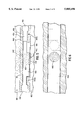
- FIG. 1 is a side elevation of a feed shoe according to one embodiment of this invention
- FIG. 2 is a front view of FIG. 1 showing the feed shoe in a horizontal plane elevated above and transverse to the die cavity.
- FIG. 3 is a front view of FIG. 1 showing the feed shoe in fill position
- FIG. 4 is a top view of FIG. 1 in the fill position
- FIG. 5 is a side view of an egress valve on a feed shoe according to one embodiment of this invention.
- FIG. 6 is a top view thereof schematically illustrating an open and a closed position of the valve.
- FIG. 7 is a front view of a pinch valve embodiment of an egress valve in the open position on the feed shoe.
- FIG. 8 is the pinch valve of FIG. 7 in the closed position.
- FIG. 9 is a side view of a pneumatic valve embodiment of the egress valve on the feed shoe.
- FIG. 10 is a diagram of a flow chart illustrating a process of the present invention.
- Feed shoe 10 as shown relates to the feeding and delivery of powdered metals into die cavity 26, the powdered metals being compacted by upper and lower punches 28 and 29.
- the teachings of this invention are not limited to the handling of metal powders, but are equally applicable to the handling of particulate materials of various weights and types including, for example, ceramics, polymers, carbides, or cements (cementatious materials blended with water).
- pressurized feed shoe 10 generally comprises feed shoe vessel 11, and pressure conduit 13 communicating with vessel 11 through air ingress 14.
- a pressure generator 40 for generating supra-atmospheric pressures within vessel 11 and die cavity 26 for delivering powder material into die cavity 26 with a uniform density which is greater than the bulk density of the powder material communicates with vessel 11 via pressure conduit 13 sealingly engaged thereto.
- the pressure generator can be used to vary the density of the powder material in the die cavity along a gradient by varying the pressure generated during powder delivery.
- Feed shoe 10 is organized to cooperate with pneumatic piston 15 and actuator cylinder 25, or any other suitable mechanical linkage known to those in the art for selectively reciprocating the pressurized feed shoe such as cams, motors, gears, hydraulic pistons, stepping motors, linear motion transducers, servio motors, etc. as will appear more clearly in association with the operational description hereinafter. Delivery of the feed shoe 10 to and from the die cavity 26 can be in a linear or non-linear motion (i.e., swinging or pivoting back and forth) over the die cavity 26.
- Shoe vessel 11 is preferably constructed of any material, such as a metal or metal alloy, that is suitable for withstanding supra-atmospheric pressures and includes rear wall 20 having a pair of laterally spaced side walls 21, 21A depending from a planar top wall 22 thereof.
- Powder ingress 36 is situated in planar top wall 22 and communicates with an optional hopper (not shown) receptive of a quantity of powder material. Powder ingress 36 is associated with an ingress valve (not shown) for maintaining pressure within shoe vessel 11 after and while it is pressurized.
- the hopper has a discharge opening at the lower end thereof and communicates with the interior of vessel 11 through a filling conduit (not shown) which enters powder ingress 36.
- One each of a pair of bridge members 23 extend from the bottom exterior of side walls 21, 21A and have elevation cylinders 30 mounted thereon.
- Piston 31 is mounted at its bottom end to guide 32 and slidably engages the interior of elevation cylinder 30.
- Pressure is applied to elevation cylinder 30 and the pressure forces the spatial separation of piston 31 from elevation cylinder 30 thereby elevating bridge member 23 to lift feed shoe vessel 11.
- Rail 33 is fixed to the wear plate of die table 34, and guides 32 slide freely in a self-aligning linear motion along rails 33, actuated by piston 15 sliding through opening 35 inside actuator cylinder 25 that is fixed to the wear plate of die table 34.
- actuator cylinder 25 In use, by applying a pressure to actuator cylinder 25 forcing the forward movement of piston 15 which is attached to feed shoe 10, feed shoe 10 moves forward.
- Vessel 11 has bottom egress opening 37.
- Valve 38 is associated with egress opening 37 and has a closed position for containing powder material inside vessel 11 and an open position for delivering powder material to die cavity 26 when egress opening 37 registers with die cavity 26.
- the feed shoe can have more than one egress opening 37 (not shown). Additionally, where it is desirable to deliver particulate material into very wide parts such as rings, gears etc., the feed shoe can have multiple egress openings (not shown).
- FIG. 2 is a front view of FIG. 1 and shows the feed shoe 10 in an elevated position above and offset from the die cavity 26. In this position, powder material is prevented from entering the die cavity 26.
- piston 31 is mounted to guide 32 and slidably engages the interior of elevation cylinder 30.
- the elevation cylinder 30 is attached to bridge member 23, which in turn is connected to the side walls 21, 21A of the feed shoe vessel 11.
- pressure has been applied to elevation cylinder 30 to force the separation of piston 31 from the elevation cylinder 30 in the upward direction indicated by the arrow.
- the upward movement of the elevation cylinder 30 in turn causes the bridge member 23 to lift in the same upward direction, thereby also raising the feed shoe vessel 11.
- the feed shoe 10 is thereby spatially separated from the die cavity 26.
- the feed shoe 10 moves transverse to the die cavity 26. This movement is accomplished by applying a pressure to actuator cylinder 25 (see FIG. 1) to force the movement of piston 15 through the opening 35 in the actuator cylinder 25. The movement of piston 15 causes guides 32 to slide along rails 33, so that the feed shoe 10 is moved to its final position above and transverse to the die cavity.
- FIG. 3 shows the feed shoe 10 in the position for filling the die cavity 26.
- a lock 71, 71A or locking mechanism as for example, a strong magnet, keeps the feed shoe registered with the die cavity during pressurized delivery of the particulate material therein.
- Valve body housing 438 is sandwiched between pressure vessel 411 and die cavity 426, defines valve cavity 439, and has upper body housing surface 440 and lower body housing surface 441.
- Upper body housing surface 440 has powder ingress 442 and lower body housing surface 441 has powder egress 443.
- Powder ingress 442 and powder egress 443 are aligned transverse with each other along a vertical axis.
- Valve slide 444 has slide hole 445 bored there through and sits within valve cavity 439.
- valve opening end 446 In operation, to open valve 437, air pressure (or an inert gas such as argon or helium) is provided through valve opening end 446 into valve cavity 439 to move valve slide 444 in a linear motion so as to align slide hole 445 with powder ingress 442 and powder egress 443 thereby creating open communication between vessel 411 and die cavity 426.
- air pressure is applied through valve closing end 447 into valve cavity 439 to move valve slide 444 to a position whereby slide hole 445 is not aligned with powder ingress 442 and powder egress 443 thereby closing communication between vessel 411 and die cavity 426 cutting off powder flow.
- Lower body valve housing 441 has mechanical stops 446 and 447 for aligning and disaligning slide hole 445 with powder ingress 442 and powder egress 443.
- FIG. 6 shows a top view of FIG. 5 viewed from within vessel 411 down through powder ingress 442, slide hole 445 which is aligned with powder ingress 442 and powder egress of valve body housing 438 in the open position. In the closed position, slide hole 445 is disaligned from powder egress 442 and powder ingress 443 so that there is no longer open communication between vessel 411 and die cavity 426.
- slide 444 and valve body housing 438 consideration must be given to the size of the smallest powders used.
- the space between the slide 444 and the interior valve housing 438 should preferably be smaller than the smallest powder particle to minimize jamming of the valve mechanism by powder.
- flexible feed tube 500 extends through bottom egress opening 537 and communicates with and is continuous with bladder 502 that lines the interior of feed shoe vessel 511.
- Flexible feed tube 500 is opened and closed by pinching and releasing the outside diameter of the tube.
- Mechanical pinchers 504, 504A are caused to pinch flexible feed tube 500 closed by the application of air through conduits 506, 506A in lower body housing 541 of feed shoe vessel 511.
- mechanical pinchers 504, 504A may begin in the pinched or closed position as shown in FIG. 8 and slide outward along conduits 506, 506A to open when pressure is generated within feed shoe vessel 511.
- Any suitable pinch valve apparatus may be employed as the egress valve.
- the pinch valve has the ability to "pinch off" immediately above the die surface of die cavity 526 sitting above lower punch 529.
- FIG. 9 shows yet another embodiment of the bottom egress valve 637.
- hopper 650 sits within vessel 611 and is receptive of a quantity of particulate material.
- Feed tube 652 communicates between the interior of hopper 650 and egress vacuum tube 654, the bottom opening 655 of which registers with bottom egress opening 661 of feed shoe vessel 611 and with die cavity 626 above lower punch 629 when feed shoe 610 is in the fill position.
- supra-atmospheric pressure is delivered through egress vacuum tube 654 which serves to pull particulate material from hopper 650 through feed tube 652 into egress vacuum tube 654 and finally into die cavity 626 through egress opening 661.
- the supra-atmospheric pressure also serves to precompact the particulate material in the die cavity.
- FIG. 4 shows an embodiment of the present invention comprising elevation cylinder 330,330A, guides 332,332A, piston 315, actuator cylinder 325, upper punch 328, piston 331, powder ingress 336, bottom egress opening 337, and further comprising a second conduit 348 extending between and openly communicating between a source of liquid solutions (not shown) and the interior of die cavity 326 when feed shoe 310 is in fill position.
- Second conduit 348 delivers liquid solutions to said die cavity.
- second conduit 348 can deliver the liquid solution to the interior of feed shoe vessel 311.
- Second conduit 348 can be constructed from a solenoid valve, as for example a zero dead volume solenoid valve, however, any dripless valve may be used.
- Solenoid valve housing 345 encases second conduit 348.
- a vacuum may be attached to the second conduit 348 to remove the liquid from the die cavity after it has been dispensed therein.
- Such a second conduit is appropriately used in those situations wherein it is preferable to add a liquid component to the die cavity prior to compacting the particles.
- Such liquid components can include, but are not limited to, aqueous solutions, lubricants, surfactants or activation solutions for atomically cleaning metal particulates for cold welding.
- the liquid components can also include any solution which is desired to be incorporated into the material, for example, water added to cement or plaster, hardener added to a polymer, solvent added to a polymer, etc.
- Feed shoes according to the present invention using activation solutions for atomically cleaning the particulate materials are useful in producing net or near net shaped parts without the need for sintering.
- the vacuum is attached to the second conduit for removing liquid solutions from the die cavity (or alternatively the feed shoe vessel)
- a vacuum may be applied to the die cavity or to the lower punch or both.
- liquid solution is sprayed into the die cavity through the second conduit and then removed from of the die cavity by the vacuum attached thereto.
- the second conduit can alternatively deliver liquid components to the interior of the feed shoe vessel.
- a vacuum or other liquid removing means is applied to the feed shoe vessel to remove the liquid component before the powders are delivered to the die cavity.
- the present invention also further comprises any known device for providing an atmosphere of an inert gas, as for example helium or argon, a gas such as nitrogen or an active gas such as O 2 , O 3 , and SO 2 around the atomically cleaned metal powders until they can be compressed in the die cavity.
- an inert gas as for example helium or argon
- a gas such as nitrogen or an active gas such as O 2 , O 3 , and SO 2
- the present invention also provides a process for producing articles of uniform density from particulate material.
- the process comprises the steps of delivering particulate material to a die cavity, generating a supra-atmospheric pressure within the die cavity to produce a uniform density of the particulate material that is greater than the material's bulk density or generating a gradient of pressure used to deliver the particulate material to the die cavity with a gradient of densities, and compacting the particulate material to form an article having a uniform density. Additional steps may be utilized if it is desired or necessary to add liquid components to the particulate material.
- the process can further comprise repeating the pressurized delivery step with a second or third particulate material.
- the feed shoe vessel is pressurized at a specified pressure for a specified time or at varying pressures for varying times.
- a specified pressure for a specified time As an example only, if copper coated aluminum is the particulate material, the feed shoe vessel should be pressurized to about 25 pounds for 1 seconds.
- Suitable pressures for use with the present invention are readily optimizable and may range from about 1 to about 125 pounds or higher and generally vary depending on the size of the die cavity, the complexity of the geometry of the die cavity, and the degree of difficulty in uniformly filling the die cavity.
- Suitable times for pressurizing are also readily optimizable and may range from less than 1 second to minutes or longer. The applicable time is also based on the size and complexity of the geometry of the die cavity and the degree of difficulty in uniformly filling the cavity.
- particulate material that has been pre-delivered to the feed shoe vessel is delivered to the die cavity with the simultaneous application of pressure and opening of the egress valve. In either case the die cavity is then filled with particulate material. In certain applications, it may be useful to fill the cavity in more than one place to accommodate a unique or complex part geometry.
- the feed shoe is lifted above the die cavity. If it is necessary or advantageous to add liquid components to the particulate material, they may be added to the die cavity at this point in the process.
- the feed shoe is returned to its initial position, and a press is activated. At the same time, a vacuum may be activated if it is desired to remove liquid components that were added to the particulate material.
- a press punch is then lowered into the die cavity and raised up to the die cavity to compact the particulate material into the desired part. The press punch may displace any liquid component that may be present in the die cavity out of the part, such that the optional vacuum may remove the liquid component from the die cavity, if desired. Finally, a lower punch ejects the finished part from the die cavity.
- Feed shoes according to the present invention can be adapted for use in any known powder press manufacturing process and can also be temperature-controlled as appropriate by, for example, insulation, heating with convection or induction, microwave systems or heat transfer methods that pump oil or hot water through pipes or coils.
- the present invention is directed to a powder press for making parts from particulate materials.
- the powder press according to the present material comprises a feed shoe for delivering particulate materials to a die cavity and a wear plate defining a die table of the powder press.
- the feed shoe comprises a vessel for receiving a particulate material; a pressure generator for generating supra-atmospheric pressures in the die cavity and the vessel; and a shuttle for moving the feed shoe to a position whereby an opening in the feed shoe aligns with the die cavity.
- the shuttle is mounted on its underside to the upper surface of the wear plate. Particulate material is transferred to the die cavity through the feed shoe.
Abstract
Description
Claims (5)
Priority Applications (1)
| Application Number | Priority Date | Filing Date | Title |
|---|---|---|---|
| US08/953,597 US5885496A (en) | 1996-08-29 | 1997-10-17 | Pressurized feedshoe apparatus and method for precompacting powdered materials |
Applications Claiming Priority (2)
| Application Number | Priority Date | Filing Date | Title |
|---|---|---|---|
| US08/705,343 US5831178A (en) | 1995-08-29 | 1996-08-29 | Vibration type measuring instrument |
| US08/953,597 US5885496A (en) | 1996-08-29 | 1997-10-17 | Pressurized feedshoe apparatus and method for precompacting powdered materials |
Related Parent Applications (1)
| Application Number | Title | Priority Date | Filing Date |
|---|---|---|---|
| US08/705,343 Division US5831178A (en) | 1995-08-29 | 1996-08-29 | Vibration type measuring instrument |
Publications (1)
| Publication Number | Publication Date |
|---|---|
| US5885496A true US5885496A (en) | 1999-03-23 |
Family
ID=24833041
Family Applications (1)
| Application Number | Title | Priority Date | Filing Date |
|---|---|---|---|
| US08/953,597 Expired - Fee Related US5885496A (en) | 1996-08-29 | 1997-10-17 | Pressurized feedshoe apparatus and method for precompacting powdered materials |
Country Status (1)
| Country | Link |
|---|---|
| US (1) | US5885496A (en) |
Cited By (4)
| Publication number | Priority date | Publication date | Assignee | Title |
|---|---|---|---|---|
| US6555040B1 (en) * | 1999-03-24 | 2003-04-29 | David Lienau | Method of making pressed earth block machine |
| US20040075185A1 (en) * | 2000-01-12 | 2004-04-22 | Jerome Dugat | Method and device for producing a straight cylindrical body by molding using aloose hardenable granular matterial and the utilization thereof for producing a tube |
| US20090274923A1 (en) * | 2008-03-04 | 2009-11-05 | Kenneth Hall | Tools Having Compacted Powder Metal Work Surfaces, And Method |
| US10295507B2 (en) | 2014-04-09 | 2019-05-21 | Eth Zurich | Method and device for multiple-frequency tracking of oscillating systems |
Citations (48)
| Publication number | Priority date | Publication date | Assignee | Title |
|---|---|---|---|---|
| US2303288A (en) * | 1938-04-15 | 1942-11-24 | Lester Engineering Co | Plastic casting machine |
| US2402367A (en) * | 1944-12-16 | 1946-06-18 | Forrest L Cantrall | Brickmaking machine |
| US2598016A (en) * | 1950-04-17 | 1952-05-27 | Hpm Dev Corp | Apparatus for hot pressing powdered metals |
| US2675584A (en) * | 1949-07-25 | 1954-04-20 | A C I Plastics Proprietary Ltd | Mold feeding apparatus |
| US2800684A (en) * | 1953-07-28 | 1957-07-30 | Ncr Co | Apparatus for forming powdered metal parts |
| US2967613A (en) * | 1955-04-28 | 1961-01-10 | 134 Woodworth Corp | Metal forming apparatus |
| US3020589A (en) * | 1960-07-28 | 1962-02-13 | Olivetti & Co Spa | Device for molding articles by compacting powder material |
| US3154812A (en) * | 1962-03-07 | 1964-11-03 | Haller John | Hydraulic briquetting press |
| US3183570A (en) * | 1960-03-21 | 1965-05-18 | Clarence W Vogt | Compacting equipment |
| US3191232A (en) * | 1961-12-07 | 1965-06-29 | Haller John | Hydraulic compacting press |
| US3574892A (en) * | 1969-01-27 | 1971-04-13 | Wolverine Pentronix | Powder compacting press |
| US3605825A (en) * | 1968-10-02 | 1971-09-20 | Mannesmann Meer Ag | Method and apparatus for filling the die of a powder press,especially of a metal powder press |
| US3647333A (en) * | 1969-11-10 | 1972-03-07 | Wolverine Pentronix | Apparatus for injecting a fluid into powdered materials being compacted |
| US3690805A (en) * | 1970-11-16 | 1972-09-12 | Baldwin Hamilton Co | Multiple fill compacting press |
| US3697208A (en) * | 1966-07-29 | 1972-10-10 | Werz Furnier Sperrholz | Apparatus for filling molds |
| US3752622A (en) * | 1970-09-22 | 1973-08-14 | Olivetti & Co Spa | Device for moulding sintering blanks |
| US3764244A (en) * | 1972-05-30 | 1973-10-09 | D Hurley | Apparatus for compacting granular material |
| US3773446A (en) * | 1970-09-10 | 1973-11-20 | Olivetti & Co Spa | Device for moulding parts to be sintered |
| US3788787A (en) * | 1971-11-26 | 1974-01-29 | H Silbereisen | Hydraulic metal powder press |
| US3972449A (en) * | 1975-08-13 | 1976-08-03 | Aeonic Press Company | Power feeding apparatus |
| US3995979A (en) * | 1973-12-05 | 1976-12-07 | Ing. C. Olivetti & C., S.P.A. | Apparatus for lubricating moulds for blanks |
| US4036575A (en) * | 1972-11-16 | 1977-07-19 | Castone Development Corporation | Concrete product manufacturing system |
| US4080128A (en) * | 1974-04-29 | 1978-03-21 | Siemens Aktiengesellschaft | Apparatus for the production of compacts of layerwise different composition, for heavy duty electric contacts |
| US4201530A (en) * | 1977-09-16 | 1980-05-06 | Bucher-Guyer Ag. | Arrangement for uniform filling of a mold cavity |
| US4260346A (en) * | 1979-10-09 | 1981-04-07 | Anderson Jr Raymond B | Press assembly for powder material |
| US4327996A (en) * | 1980-09-02 | 1982-05-04 | Cts Corporation | Apparatus for controlling the movement of press components |
| US4352648A (en) * | 1980-12-22 | 1982-10-05 | Toolmakers, Incorporated | Powdered metal press and tooling therefor |
| US4359175A (en) * | 1980-11-14 | 1982-11-16 | Kelsey-Hayes Company | Adjustable vibrating powder dispensing assembly |
| US4377376A (en) * | 1981-09-24 | 1983-03-22 | Ptx-Pentronix, Inc. | Indexing mechanism for the anvil assembly of a powder-compacting press |
| US4401614A (en) * | 1981-09-08 | 1983-08-30 | Ptx-Pentronix, Inc. | Anvil assembly for a powder-compacting anvil press |
| US4488837A (en) * | 1981-07-14 | 1984-12-18 | Kabushiki Kaisha Kobe Seiko Sho | Method for measuring integrated weight of particulate feed material |
| US4591326A (en) * | 1984-02-13 | 1986-05-27 | Alkem Gmbh | Pressing device for producing compacts from source material in powder form, in particular pulverized nuclear reactor fuel |
| US4788023A (en) * | 1983-10-31 | 1988-11-29 | Eugen Buhler and Hutschenreuther AG | Process and apparatus for producing a dry-pressed moulding from a particulate or granular moulding material |
| US4813818A (en) * | 1987-08-25 | 1989-03-21 | Michael Sanzone | Apparatus and method for feeding powdered materials |
| US4818201A (en) * | 1987-11-19 | 1989-04-04 | Martin Sprocket & Gear, Inc. | Method of manufacturing bushings with powdered metals |
| US4853180A (en) * | 1987-11-19 | 1989-08-01 | Martin Sprocket & Gear, Inc. | Method of manufacturing bushings with powdered metals |
| US5037287A (en) * | 1987-06-15 | 1991-08-06 | Akira Hirai | Pressure molding means for powder |
| US5071289A (en) * | 1989-12-27 | 1991-12-10 | Alpheus Cleaning Technologies Corp. | Particulate delivery system |
| US5074774A (en) * | 1989-08-10 | 1991-12-24 | Kabushiki Kaisha Mitsuishi Fukai Tekkosho | Weight scaling material supplying apparatus for a powder molding machine |
| US5184754A (en) * | 1990-10-18 | 1993-02-09 | Hansen Thomas N | Weight-controlled particulate matter feed system |
| US5222529A (en) * | 1990-12-21 | 1993-06-29 | American Cyanamid Company | Filling apparatus |
| US5236021A (en) * | 1991-12-23 | 1993-08-17 | General Electric Company | Powder filling apparatus |
| US5253993A (en) * | 1990-08-21 | 1993-10-19 | Bayer Aktiengesellschaft | Apparatus for the production of pellets of metal powder used as catalysts |
| US5256053A (en) * | 1990-12-26 | 1993-10-26 | Kabushiki Kaisha Mitsuishi Fukai Tekkosho | Brick press |
| US5269463A (en) * | 1991-09-16 | 1993-12-14 | Plastic Flamecoat Systems, Inc. | Fluidized powder feed system with pressurized hopper |
| US5460827A (en) * | 1991-04-12 | 1995-10-24 | Elizabeth-Hata International, Inc. | Elongated cylindrical medicinal tablet having two layers |
| US5472661A (en) * | 1994-12-16 | 1995-12-05 | General Motors Corporation | Method of adding particulate additives to metal particles |
| US5629033A (en) * | 1995-10-16 | 1997-05-13 | Lienau; David | Pressed earth block machine |
-
1997
- 1997-10-17 US US08/953,597 patent/US5885496A/en not_active Expired - Fee Related
Patent Citations (48)
| Publication number | Priority date | Publication date | Assignee | Title |
|---|---|---|---|---|
| US2303288A (en) * | 1938-04-15 | 1942-11-24 | Lester Engineering Co | Plastic casting machine |
| US2402367A (en) * | 1944-12-16 | 1946-06-18 | Forrest L Cantrall | Brickmaking machine |
| US2675584A (en) * | 1949-07-25 | 1954-04-20 | A C I Plastics Proprietary Ltd | Mold feeding apparatus |
| US2598016A (en) * | 1950-04-17 | 1952-05-27 | Hpm Dev Corp | Apparatus for hot pressing powdered metals |
| US2800684A (en) * | 1953-07-28 | 1957-07-30 | Ncr Co | Apparatus for forming powdered metal parts |
| US2967613A (en) * | 1955-04-28 | 1961-01-10 | 134 Woodworth Corp | Metal forming apparatus |
| US3183570A (en) * | 1960-03-21 | 1965-05-18 | Clarence W Vogt | Compacting equipment |
| US3020589A (en) * | 1960-07-28 | 1962-02-13 | Olivetti & Co Spa | Device for molding articles by compacting powder material |
| US3191232A (en) * | 1961-12-07 | 1965-06-29 | Haller John | Hydraulic compacting press |
| US3154812A (en) * | 1962-03-07 | 1964-11-03 | Haller John | Hydraulic briquetting press |
| US3697208A (en) * | 1966-07-29 | 1972-10-10 | Werz Furnier Sperrholz | Apparatus for filling molds |
| US3605825A (en) * | 1968-10-02 | 1971-09-20 | Mannesmann Meer Ag | Method and apparatus for filling the die of a powder press,especially of a metal powder press |
| US3574892A (en) * | 1969-01-27 | 1971-04-13 | Wolverine Pentronix | Powder compacting press |
| US3647333A (en) * | 1969-11-10 | 1972-03-07 | Wolverine Pentronix | Apparatus for injecting a fluid into powdered materials being compacted |
| US3773446A (en) * | 1970-09-10 | 1973-11-20 | Olivetti & Co Spa | Device for moulding parts to be sintered |
| US3752622A (en) * | 1970-09-22 | 1973-08-14 | Olivetti & Co Spa | Device for moulding sintering blanks |
| US3690805A (en) * | 1970-11-16 | 1972-09-12 | Baldwin Hamilton Co | Multiple fill compacting press |
| US3788787A (en) * | 1971-11-26 | 1974-01-29 | H Silbereisen | Hydraulic metal powder press |
| US3764244A (en) * | 1972-05-30 | 1973-10-09 | D Hurley | Apparatus for compacting granular material |
| US4036575A (en) * | 1972-11-16 | 1977-07-19 | Castone Development Corporation | Concrete product manufacturing system |
| US3995979A (en) * | 1973-12-05 | 1976-12-07 | Ing. C. Olivetti & C., S.P.A. | Apparatus for lubricating moulds for blanks |
| US4080128A (en) * | 1974-04-29 | 1978-03-21 | Siemens Aktiengesellschaft | Apparatus for the production of compacts of layerwise different composition, for heavy duty electric contacts |
| US3972449A (en) * | 1975-08-13 | 1976-08-03 | Aeonic Press Company | Power feeding apparatus |
| US4201530A (en) * | 1977-09-16 | 1980-05-06 | Bucher-Guyer Ag. | Arrangement for uniform filling of a mold cavity |
| US4260346A (en) * | 1979-10-09 | 1981-04-07 | Anderson Jr Raymond B | Press assembly for powder material |
| US4327996A (en) * | 1980-09-02 | 1982-05-04 | Cts Corporation | Apparatus for controlling the movement of press components |
| US4359175A (en) * | 1980-11-14 | 1982-11-16 | Kelsey-Hayes Company | Adjustable vibrating powder dispensing assembly |
| US4352648A (en) * | 1980-12-22 | 1982-10-05 | Toolmakers, Incorporated | Powdered metal press and tooling therefor |
| US4488837A (en) * | 1981-07-14 | 1984-12-18 | Kabushiki Kaisha Kobe Seiko Sho | Method for measuring integrated weight of particulate feed material |
| US4401614A (en) * | 1981-09-08 | 1983-08-30 | Ptx-Pentronix, Inc. | Anvil assembly for a powder-compacting anvil press |
| US4377376A (en) * | 1981-09-24 | 1983-03-22 | Ptx-Pentronix, Inc. | Indexing mechanism for the anvil assembly of a powder-compacting press |
| US4788023A (en) * | 1983-10-31 | 1988-11-29 | Eugen Buhler and Hutschenreuther AG | Process and apparatus for producing a dry-pressed moulding from a particulate or granular moulding material |
| US4591326A (en) * | 1984-02-13 | 1986-05-27 | Alkem Gmbh | Pressing device for producing compacts from source material in powder form, in particular pulverized nuclear reactor fuel |
| US5037287A (en) * | 1987-06-15 | 1991-08-06 | Akira Hirai | Pressure molding means for powder |
| US4813818A (en) * | 1987-08-25 | 1989-03-21 | Michael Sanzone | Apparatus and method for feeding powdered materials |
| US4853180A (en) * | 1987-11-19 | 1989-08-01 | Martin Sprocket & Gear, Inc. | Method of manufacturing bushings with powdered metals |
| US4818201A (en) * | 1987-11-19 | 1989-04-04 | Martin Sprocket & Gear, Inc. | Method of manufacturing bushings with powdered metals |
| US5074774A (en) * | 1989-08-10 | 1991-12-24 | Kabushiki Kaisha Mitsuishi Fukai Tekkosho | Weight scaling material supplying apparatus for a powder molding machine |
| US5071289A (en) * | 1989-12-27 | 1991-12-10 | Alpheus Cleaning Technologies Corp. | Particulate delivery system |
| US5253993A (en) * | 1990-08-21 | 1993-10-19 | Bayer Aktiengesellschaft | Apparatus for the production of pellets of metal powder used as catalysts |
| US5184754A (en) * | 1990-10-18 | 1993-02-09 | Hansen Thomas N | Weight-controlled particulate matter feed system |
| US5222529A (en) * | 1990-12-21 | 1993-06-29 | American Cyanamid Company | Filling apparatus |
| US5256053A (en) * | 1990-12-26 | 1993-10-26 | Kabushiki Kaisha Mitsuishi Fukai Tekkosho | Brick press |
| US5460827A (en) * | 1991-04-12 | 1995-10-24 | Elizabeth-Hata International, Inc. | Elongated cylindrical medicinal tablet having two layers |
| US5269463A (en) * | 1991-09-16 | 1993-12-14 | Plastic Flamecoat Systems, Inc. | Fluidized powder feed system with pressurized hopper |
| US5236021A (en) * | 1991-12-23 | 1993-08-17 | General Electric Company | Powder filling apparatus |
| US5472661A (en) * | 1994-12-16 | 1995-12-05 | General Motors Corporation | Method of adding particulate additives to metal particles |
| US5629033A (en) * | 1995-10-16 | 1997-05-13 | Lienau; David | Pressed earth block machine |
Cited By (6)
| Publication number | Priority date | Publication date | Assignee | Title |
|---|---|---|---|---|
| US6555040B1 (en) * | 1999-03-24 | 2003-04-29 | David Lienau | Method of making pressed earth block machine |
| US20040075185A1 (en) * | 2000-01-12 | 2004-04-22 | Jerome Dugat | Method and device for producing a straight cylindrical body by molding using aloose hardenable granular matterial and the utilization thereof for producing a tube |
| US6911168B2 (en) * | 2000-01-12 | 2005-06-28 | Bouygues Travaux Publics | Method and device for producing a straight cylindrical body by molding using a loose hardenable granular material and the utilization thereof for producing a tube |
| US20090274923A1 (en) * | 2008-03-04 | 2009-11-05 | Kenneth Hall | Tools Having Compacted Powder Metal Work Surfaces, And Method |
| DE112009000504T5 (en) | 2008-03-04 | 2011-03-17 | Irwin Industrial Tool Co. | Tools with work surfaces of compacted powder metal and process |
| US10295507B2 (en) | 2014-04-09 | 2019-05-21 | Eth Zurich | Method and device for multiple-frequency tracking of oscillating systems |
Similar Documents
| Publication | Publication Date | Title |
|---|---|---|
| US5945135A (en) | Pressurized feedshoe apparatus and method for precompacting powdered materials | |
| US6241935B1 (en) | Pulsed pressurized powder feed system and method for uniform particulate material delivery | |
| EP0488334B1 (en) | Method and apparatus for producing a permanent magnet by forming a green and sintered compact | |
| US5672363A (en) | Production apparatus for making green compact | |
| US6309594B1 (en) | Metal consolidation process employing microwave heated pressure transmitting particulate | |
| US20050220921A1 (en) | Dynamic forging impact energy retention machine | |
| JPH0773798B2 (en) | Method of forming permanent magnet body | |
| US7252120B2 (en) | Powder feed apparatus, system and method | |
| US6814928B2 (en) | Method of making sintered articles | |
| US5885496A (en) | Pressurized feedshoe apparatus and method for precompacting powdered materials | |
| WO2001026846A2 (en) | Fluidized fillshoe system | |
| US5887642A (en) | Pressurized squeeze casting apparatus and method and low pressure furnace for use therewith | |
| CN1222109A (en) | Pressurized feed shoe appts. and process for precompacting powdered materials | |
| EP0988959A2 (en) | Powder compaction method | |
| US3157914A (en) | Automatic apparatus for producing members from powders | |
| US4354818A (en) | Moulding apparatus for compacting powdered materials | |
| MXPA99007493A (en) | Pulsed pressurized powder feed system and method for uniform particulate material delivery | |
| DE19530296A1 (en) | Feeding device for powder material | |
| CZ290099A3 (en) | Pulsating pressure feeding system of dust and method of uniform supply of dusty material | |
| KR20090087068A (en) | A filling shoe and method for powder filling and compaction | |
| WO2010128953A1 (en) | Method and apparatus for forming and pressing powder materials | |
| GB2074086A (en) | Moulding apparatus for compacting powdered materials | |
| WO2003043764A2 (en) | Hydraulic modular manufacturing system | |
| JPH0515761B2 (en) | ||
| AU2003206281A1 (en) | A dynamic forging impact energy retention machine |
Legal Events
| Date | Code | Title | Description |
|---|---|---|---|
| REMI | Maintenance fee reminder mailed | ||
| FEPP | Fee payment procedure |
Free format text: PETITION RELATED TO MAINTENANCE FEES FILED (ORIGINAL EVENT CODE: PMFP); ENTITY STATUS OF PATENT OWNER: SMALL ENTITY |
|
| FEPP | Fee payment procedure |
Free format text: PETITION RELATED TO MAINTENANCE FEES GRANTED (ORIGINAL EVENT CODE: PMFG); ENTITY STATUS OF PATENT OWNER: SMALL ENTITY |
|
| REIN | Reinstatement after maintenance fee payment confirmed | ||
| FP | Lapsed due to failure to pay maintenance fee |
Effective date: 20030323 |
|
| FPAY | Fee payment |
Year of fee payment: 4 |
|
| SULP | Surcharge for late payment | ||
| PRDP | Patent reinstated due to the acceptance of a late maintenance fee |
Effective date: 20030710 |
|
| AS | Assignment |
Owner name: BEANE, GLENN L., NEW HAMPSHIRE Free format text: ASSIGNMENT OF ASSIGNORS INTEREST;ASSIGNOR:MATERIALS INNOVATION INC.;REEL/FRAME:015612/0379 Effective date: 20041215 Owner name: LASHMORE, DAVID S., NEW HAMPSHIRE Free format text: ASSIGNMENT OF ASSIGNORS INTEREST;ASSIGNOR:MATERIALS INNOVATION INC.;REEL/FRAME:015612/0379 Effective date: 20041215 |
|
| AS | Assignment |
Owner name: GLENN BEANE, LLC, NEW HAMPSHIRE Free format text: ASSIGNMENT OF ASSIGNORS INTEREST;ASSIGNORS:BEANE, GLENN L.;LASHMORE, DAVID S.;REEL/FRAME:015711/0749 Effective date: 20041216 |
|
| REMI | Maintenance fee reminder mailed | ||
| LAPS | Lapse for failure to pay maintenance fees | ||
| STCH | Information on status: patent discontinuation |
Free format text: PATENT EXPIRED DUE TO NONPAYMENT OF MAINTENANCE FEES UNDER 37 CFR 1.362 |
|
| FP | Lapsed due to failure to pay maintenance fee |
Effective date: 20070328 |