EP0412727B1 - Optisches Übertragungssystem - Google Patents
Optisches Übertragungssystem Download PDFInfo
- Publication number
- EP0412727B1 EP0412727B1 EP90308536A EP90308536A EP0412727B1 EP 0412727 B1 EP0412727 B1 EP 0412727B1 EP 90308536 A EP90308536 A EP 90308536A EP 90308536 A EP90308536 A EP 90308536A EP 0412727 B1 EP0412727 B1 EP 0412727B1
- Authority
- EP
- European Patent Office
- Prior art keywords
- fiber
- amplifying
- transmission
- signal
- optical
- Prior art date
- Legal status (The legal status is an assumption and is not a legal conclusion. Google has not performed a legal analysis and makes no representation as to the accuracy of the status listed.)
- Expired - Lifetime
Links
Images

Classifications
-
- H—ELECTRICITY
- H04—ELECTRIC COMMUNICATION TECHNIQUE
- H04B—TRANSMISSION
- H04B10/00—Transmission systems employing electromagnetic waves other than radio-waves, e.g. infrared, visible or ultraviolet light, or employing corpuscular radiation, e.g. quantum communication
- H04B10/29—Repeaters
- H04B10/291—Repeaters in which processing or amplification is carried out without conversion of the main signal from optical form
-
- G—PHYSICS
- G02—OPTICS
- G02B—OPTICAL ELEMENTS, SYSTEMS OR APPARATUS
- G02B6/00—Light guides; Structural details of arrangements comprising light guides and other optical elements, e.g. couplings
- G02B6/24—Coupling light guides
- G02B6/26—Optical coupling means
- G02B6/28—Optical coupling means having data bus means, i.e. plural waveguides interconnected and providing an inherently bidirectional system by mixing and splitting signals
- G02B6/2804—Optical coupling means having data bus means, i.e. plural waveguides interconnected and providing an inherently bidirectional system by mixing and splitting signals forming multipart couplers without wavelength selective elements, e.g. "T" couplers, star couplers
- G02B6/2821—Optical coupling means having data bus means, i.e. plural waveguides interconnected and providing an inherently bidirectional system by mixing and splitting signals forming multipart couplers without wavelength selective elements, e.g. "T" couplers, star couplers using lateral coupling between contiguous fibres to split or combine optical signals
-
- H—ELECTRICITY
- H01—ELECTRIC ELEMENTS
- H01S—DEVICES USING THE PROCESS OF LIGHT AMPLIFICATION BY STIMULATED EMISSION OF RADIATION [LASER] TO AMPLIFY OR GENERATE LIGHT; DEVICES USING STIMULATED EMISSION OF ELECTROMAGNETIC RADIATION IN WAVE RANGES OTHER THAN OPTICAL
- H01S3/00—Lasers, i.e. devices using stimulated emission of electromagnetic radiation in the infrared, visible or ultraviolet wave range
- H01S3/05—Construction or shape of optical resonators; Accommodation of active medium therein; Shape of active medium
- H01S3/06—Construction or shape of active medium
- H01S3/063—Waveguide lasers, i.e. whereby the dimensions of the waveguide are of the order of the light wavelength
- H01S3/067—Fibre lasers
- H01S3/06754—Fibre amplifiers
-
- H—ELECTRICITY
- H01—ELECTRIC ELEMENTS
- H01S—DEVICES USING THE PROCESS OF LIGHT AMPLIFICATION BY STIMULATED EMISSION OF RADIATION [LASER] TO AMPLIFY OR GENERATE LIGHT; DEVICES USING STIMULATED EMISSION OF ELECTROMAGNETIC RADIATION IN WAVE RANGES OTHER THAN OPTICAL
- H01S3/00—Lasers, i.e. devices using stimulated emission of electromagnetic radiation in the infrared, visible or ultraviolet wave range
- H01S3/10—Controlling the intensity, frequency, phase, polarisation or direction of the emitted radiation, e.g. switching, gating, modulating or demodulating
- H01S3/13—Stabilisation of laser output parameters, e.g. frequency or amplitude
- H01S3/1301—Stabilisation of laser output parameters, e.g. frequency or amplitude in optical amplifiers
- H01S3/13013—Stabilisation of laser output parameters, e.g. frequency or amplitude in optical amplifiers by controlling the optical pumping
-
- H—ELECTRICITY
- H04—ELECTRIC COMMUNICATION TECHNIQUE
- H04B—TRANSMISSION
- H04B10/00—Transmission systems employing electromagnetic waves other than radio-waves, e.g. infrared, visible or ultraviolet light, or employing corpuscular radiation, e.g. quantum communication
- H04B10/29—Repeaters
- H04B10/291—Repeaters in which processing or amplification is carried out without conversion of the main signal from optical form
- H04B10/2912—Repeaters in which processing or amplification is carried out without conversion of the main signal from optical form characterised by the medium used for amplification or processing
-
- H—ELECTRICITY
- H01—ELECTRIC ELEMENTS
- H01S—DEVICES USING THE PROCESS OF LIGHT AMPLIFICATION BY STIMULATED EMISSION OF RADIATION [LASER] TO AMPLIFY OR GENERATE LIGHT; DEVICES USING STIMULATED EMISSION OF ELECTROMAGNETIC RADIATION IN WAVE RANGES OTHER THAN OPTICAL
- H01S3/00—Lasers, i.e. devices using stimulated emission of electromagnetic radiation in the infrared, visible or ultraviolet wave range
- H01S3/09—Processes or apparatus for excitation, e.g. pumping
- H01S3/091—Processes or apparatus for excitation, e.g. pumping using optical pumping
- H01S3/094—Processes or apparatus for excitation, e.g. pumping using optical pumping by coherent light
- H01S3/094003—Processes or apparatus for excitation, e.g. pumping using optical pumping by coherent light the pumped medium being a fibre
- H01S3/094011—Processes or apparatus for excitation, e.g. pumping using optical pumping by coherent light the pumped medium being a fibre with bidirectional pumping, i.e. with injection of the pump light from both two ends of the fibre
-
- H—ELECTRICITY
- H01—ELECTRIC ELEMENTS
- H01S—DEVICES USING THE PROCESS OF LIGHT AMPLIFICATION BY STIMULATED EMISSION OF RADIATION [LASER] TO AMPLIFY OR GENERATE LIGHT; DEVICES USING STIMULATED EMISSION OF ELECTROMAGNETIC RADIATION IN WAVE RANGES OTHER THAN OPTICAL
- H01S3/00—Lasers, i.e. devices using stimulated emission of electromagnetic radiation in the infrared, visible or ultraviolet wave range
- H01S3/09—Processes or apparatus for excitation, e.g. pumping
- H01S3/091—Processes or apparatus for excitation, e.g. pumping using optical pumping
- H01S3/094—Processes or apparatus for excitation, e.g. pumping using optical pumping by coherent light
- H01S3/09408—Pump redundancy
Definitions
- This invention relates generally to optical communication systems and more particularly to coupling an optical fiber amplifier of one mode dimension to an optical fiber communication system having a fiber of a second mode dimension.
- rare earth doped optical amplifying fibers are low cost, have low noise properties, have a relatively large bandwidth which is not polarization dependent, have no crosstalk problems, and have relatively low insertion losses at the wavelengths which are used in optical communications.
- rare earth doped optical fiber amplifiers are coupled end-to-end to an optical communication fiber and are normally transversely coupled, through a directional coupler to a laser diode pump so that a weak optical input signal at some wavelength within the rare earth doped optical fiber amplifier experiences a gain.
- the directional coupler is designed to have a high coupling ratio at the pump wavelength and low coupling ratio at the signal wavelength.
- the pump light may be made to propagate either co-directionally or contra-directionally with respect to the signal, according to whether the unconverted pump light can be more conveniently filtered at the transmitter or the receiver.
- the core diameters and refractive index profiles determines the mode sizes of the undoped transmission fiber and of the doped amplifying fiber and, therefore, the fibers will not necessarily be the same.
- the primary constraint is the requirement of waveguide dispersion while in the amplifying fiber there exists the need to maximize the overlap of the pump and signal modes. Because the amplifying fiber can have a mode size which is different from that of the transmission fiber, the losses at the splice due to mode mismatch can be quite large. To reduce this loss at the core-to-core splice between the two fibers, it has been proposed that the fusion splice be tapered.
- EP-A-143561 describes an optical communication system as described in the preamble of claim 1.
- an optical communications system as defined in claim 1.
- This invention is directed toward reducing substantially the loss incurred when two optical fibers of different mode diameters are coupled together.
- the coupling of one fiber to that of another where the fibers are of different mode diameters is not with a tapered fusion, core-to-core splice, but with an evanescent field fiber coupler.
- an amplifying fiber is inserted into the system at one or a plurality of locations. More specifically, at a desired location, the transmission fiber is severed to provide two sections and the severed sections are transversely coupled to the amplifying fiber.
- the weak signal from the first section of the transmission fiber is coupled into the amplifying fiber via a first evanescent field type of fiber coupler, and the amplified signal is coupled from the amplifying fiber to the second section of the transmission fiber via a second evanescent field type of fiber coupler.
- the first evanescent field type of fiber coupler is designed to couple substantially all of the signal energy from the first section of the transmission fiber to the amplifying fiber and to couple substantially none of the laser diode pump signal or energy from the amplifying fiber to the transmission fiber.
- the second evanescent field type of fiber coupler is designed to couple substantially all of the signal energy in the amplifying fiber to the transmitting fiber and substantially no laser diode pump energy is transferred from the amplifying fiber to the transmission fiber. Either or both cut ends of the transmission fiber can be coupled to monitor devices to detect and determine the value of the signal being coupled into and/or out of the amplifying fiber to control, for example, the gain of the amplifying fiber.
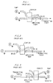
- FIGS. 1-3 there are illustrated schematics of prior art arrangements of three amplifying fibers coupled to an optical fiber transmission system.
- the amplifying fiber can be located at the transmitting end, in the middle of the transmission fiber or at the receiver end.
- FIG. 1 illustrates a rare earth doped amplifying fiber being used to increase the output from a weak source prior to transmission in a large system fiber.
- FIG. 2 illustrates what is considered to be the most important use where the amplifier is inserted at one or more locations in the middle of a system.
- FIG. 3 illustrates a doped amplifying fiber being used to amplify a weak signal to a value which can be detected by a receiver. While not illustrated, it is to be noted that optical isolators with small insertion loss may be required, in certain applications, on one or each side of the fiber system, i.e. on the signal laser side, the detector side, or on the transmission fiber. In each instance, the doped amplifying fiber is coupled by a core-to-core fusion splice to the transmission fiber.
- a laser diode pump is coupled to the optical fiber to supply the required pump energy to the amplifying fiber via a dichroic coupler.
- the amplifying fiber is coupled to the transmission fiber via fusion splices and the pump energy is supplied to the amplifying fiber via the optical fiber and dichroic coupler.
- a first section 40 of an optical transmission optical fiber coupled to receive and carry an optical signal is coupled at end 42 to the end 46 of a doped amplifying fiber 44 via an evanescent field type of coupler such as dichroic coupler 48.
- the other end 50 of the doped amplifying fiber 44 is coupled to a second section 52 at or near the end 54 of a second section 52 of the optical transmission fiber via an evanescent field type of coupler such as dichroic coupler 56.
- the dichroic coupler is comprised of two different fibers, one fiber being the transmission fiber 40 and the other fiber being the doped amplifying fiber 44.
- the refractive index and core size of the amplifying fiber is designed to optimize the overlap between pump and lasing modes and to allow coupling between the amplifying fiber and transmission fiber only at the signal wavelength.
- Dichroic couplers are described in the Publications "Analysis of a Tunable Single Mode Optical Fiber Coupler" by Michel J. F. Digonnet et al, IEEE Journal of Quantum Electronics, Vol QE-18, No.
- a length of optical fiber is securely fastened into a groove cut into a quartz block having parallel, polished faces.
- the surface of the substrate is ground and polished until the required proximity to the fiber core is obtained.
- two substrates are joined together and a liquid having a refractive index close to that of the fiber cladding is inserted between the substrates to form the coupler.
- Light from a laser diode pump 58 is launched through a lens 60 located at the very end 62 of the doped amplifying fiber 44.
- a holographic grating 64 can be positioned within the amplifying fiber between the end 62 and the coupler 48 to reject an undesired mode from the laser diode pump by providing the required backscattering.
- the length of the end 46 is kept small and the concentration of the dopant in the end 46 is kept low to keep to a minimum the absorption of pump energy in the end 46 of the amplifying fiber 44.
- Dichroic coupler 48 is constructed to couple substantially all of the signal in the transmission fiber 40 to the amplifying fiber 44.
- the dichroic coupler 48 is also constructed to couple substantially none of the pump signal from the pump to the transmission fiber 40.
- the signal in the transmission fiber 40 is coupled into the amplifying fiber 44; and the energy from the pump 58 which enters the end 46 of the fiber passes through the dichroic coupler 48 to the fiber 44. Only a very small portion of the energy from the pump 58 passes through the dichroic coupler 48 to the fiber 40.
- the dichroic coupler 56 is designed to couple substantially all of the signal energy from the amplifying fiber 44 into the second section 52 of the transmission fiber.
- dichroic coupler 48 the small amount of signal energy in the transmission fiber that passes straight through the dichroic coupler to the end 42 can be used for monitoring the operation of the system.
- the signal at the end 54 of the second section 52 of the transmission fiber which is received from the amplifying fiber 44 via coupler 56 can be used for monitoring purposes.
- a transmission fiber has a mode diameter which is different from that of the core diameter of an Erbium doped amplifying fiber.
- the Erbium doped amplifying fiber By coupling the Erbium doped amplifying fiber to the transmission fiber through an evanescent field type of coupler rather than through a direct in line core-to-core splice, the coupling losses are reduced substantially.
- commercially available high power pump lasers have several longitudinal modes where the pump modes generated occur at the pump wavelength of 1.48 um and also occur at the signal wavelength which cna be between 1.50 to 1.55 um.
- the evanescent field coupler in addition to operating as an efficient coupler between the Erbium doped amplifying fiber and the transmission fiber, also functions as a bandpass filter to reject the modes of the pump signal which have wavelengths within the signal band of 1.50-1.55 um from reaching the amplifying fiber.
- those signals generated by the laser diode pump which have a wavelength between 1.50 and 1.55 um are shunted from the amplifying fiber 44 to the first section 40 of the transmission fiber by the dichroic coupler 48.
- the longitudinal modes having wavelengths between 1.50 and 1.55 um which are generated by the pump laser diode, if not shunted by the dichroic coupler 48 from fiber 44 to fiber 40, would be a source of undesirable noise.
- the signal on fiber 40 can be monitored both before and after amplification.
- additional amplification of the input signal may be desired.
- This can be effected by coupling a backup laser diode pump 66 to the end 50 of amplifying fiber 44.
- the backup laser diode pump 66 and the laser diode pump 58 can operate simultaneously ro provide increased amplification and reduce power requirement for each pump diode, or they can operate sequentially, the backup laser diode pump 66 becoming operative only when the laser diode pump 58 decreases in output power or becomes inoperative.
- a transmission fiber 68 is coupled via a dichroic coupler to the end 50 of fiber 44.
- Dichroic coupler 70 is constructed to couple amplified energy from fiber 50 to fiber 68.
- An optical detector 72 which converts an optical signal to an electrical signal, is positioned to detect the signal present in fiber 68.
- the electrical signal generated by optical detector 70 is coupled to an input terminal of an amplifier 74, the output of which is coupled to control the operation of laser diode pump 58.
- the operation of pump 66 can be controlled to provide automatic gain control.
- the laser diode pump 58 or 66 generates a primary signal having a wavelength of 1.48 um. It is to be noted, however, that the diode pump can generate a signal having a wavelength of 0.98 um.
- a laser diode pump which generates a signal having a wavelength of 0.98 um is used, the problems associated with having undesired modes in the 1.50 to 1.55 um wavelength are not normally present.
- the use of a laser diode pump which operates at 0.98 um requires an Erbium doped amplifying fiber having a different mode diameter. However, by using the dichroic coupler, the coupling losses between the transmission fiber and the amplifying fiber are minimal regardless of the mode diameter of the transmission fiber and the mode diameter of the amplifying fiber.
Claims (3)
- Optisches Übertragungssystem mit einer Übertragungsfaser (40) zum Übertragen eines optischen Signals, wobei die besagte Übertragungsfaser einen Durchmesser mit einem ersten Modus aufweist, einer seltenerddotierten optischen Verstärkungsfaser (44) mit einem Durchmesser mit einem zweiten Modus, wobei besagter erster Durchmesser und zweiter Durchmesser ungleich sind, einer Quelle von Pumpenergie zum Pumpen der besagten seltenerddotierten optischen Verstärkungsfaser, dadurch gekennzeichnet, daß das System weiterhin einen dichroitischen Koppler (48) mit zwei Fasern enthält, wobei eine Faser die Übertragungsfaser (40, 52) ist und die andere Faser die seltenerddotierte optische Verstärkungsfaser (44) ist, wobei die besagte Verstärkungsfaser mit einem ersten Ende direkt an eine Quelle von Pumpenergie ankoppelbar ist, wobei die besagten Fasern des Kopplers nebeneinander gelegt sind, um das Signal in der Übertragungsfaser an die Verstärkungsfaser anzukoppeln und das Einkoppeln von Pumpenergie in der Verstärkungsfaser in die Übertragungsfaser zu sperren.
- Optisches Übertragungssystem nach Anspruch 1 mit einem zweiten dichroitischen Koppler mit zwei Fasern, wobei eine Faser die Übertragungsfaser und die andere Faser die seltenerddotierte optische Verstärkungsfaser ist, wobei die besagten Fasern nebeneinandergelegt sind, um das Signal in der Verstärkungsfaser in die Übertragungsfaser anzukoppeln und das Einkoppeln von Pumpenergie in der Verstärkungsfaser in die Übertragungsfaser zu sperren, wobei der besagte erste dichroitische Koppler neben einem Ende der besagten Verstärkungsfaser angekoppelt ist und der besagte zweite dichroitische Koppler neben dem anderen Ende der besagten Verstärkungsfaser angekoppelt ist.
- Optisches System nach Anspruch 2, wobei die besagte seltenerddotierte optische Verstärkungsfaser Erbium umfaßt.
Applications Claiming Priority (2)
| Application Number | Priority Date | Filing Date | Title |
|---|---|---|---|
| US07/390,864 US4963832A (en) | 1989-08-08 | 1989-08-08 | Erbium-doped fiber amplifier coupling device |
| US390864 | 2003-03-18 |
Publications (3)
| Publication Number | Publication Date |
|---|---|
| EP0412727A2 EP0412727A2 (de) | 1991-02-13 |
| EP0412727A3 EP0412727A3 (en) | 1992-01-29 |
| EP0412727B1 true EP0412727B1 (de) | 1996-06-12 |
Family
ID=23544252
Family Applications (1)
| Application Number | Title | Priority Date | Filing Date |
|---|---|---|---|
| EP90308536A Expired - Lifetime EP0412727B1 (de) | 1989-08-08 | 1990-08-02 | Optisches Übertragungssystem |
Country Status (6)
| Country | Link |
|---|---|
| US (1) | US4963832A (de) |
| EP (1) | EP0412727B1 (de) |
| JP (1) | JP2933998B2 (de) |
| CA (1) | CA2020759C (de) |
| DE (1) | DE69027378T2 (de) |
| ES (1) | ES2087893T3 (de) |
Families Citing this family (62)
| Publication number | Priority date | Publication date | Assignee | Title |
|---|---|---|---|---|
| JP2745663B2 (ja) * | 1989-04-04 | 1998-04-28 | 松下電器産業株式会社 | 充電制御回路 |
| US5125066A (en) * | 1989-07-20 | 1992-06-23 | Sumitomo Electric Industries, Ltd. | Fiber optical amplifier |
| JP3137632B2 (ja) * | 1989-08-31 | 2001-02-26 | 富士通株式会社 | 光ファイバ増幅器を備えた光通信方式 |
| JP3062204B2 (ja) * | 1989-10-13 | 2000-07-10 | 三菱電線工業株式会社 | 光増幅器 |
| IT1236632B (it) * | 1989-10-24 | 1993-03-25 | Pirelli Cavi Spa | Amplificatore per linee di telecomunicazioni a fibre ottiche e linee di telecomunicazioni a fibre ottiche incorporanti detto amplificatore |
| IT1237135B (it) * | 1989-10-30 | 1993-05-24 | Pirelli Cavi Spa | Gruppo di amplificazione ottico a basso rumore, con riflessione della potenza di pompaggio. |
| US5039199A (en) * | 1989-12-29 | 1991-08-13 | At&T Bell Laboratories | Lightwave transmission system having remotely pumped quasi-distributed amplifying fibers |
| US5638204A (en) * | 1990-01-22 | 1997-06-10 | Pirelli Cavi S.P.A. | Optical power amplifier with Al2 O3 and erbium doped active fiber |
| GB2240228B (en) * | 1990-01-23 | 1993-11-03 | Stc Plc | Optical transmission system. |
| DE4002369A1 (de) * | 1990-01-27 | 1991-08-01 | Standard Elektrik Lorenz Ag | Mehrstufiger faseroptischer verstaerker |
| GB9008895D0 (en) * | 1990-04-20 | 1990-06-20 | British Telecomm | Optical communications link fault signalling |
| FR2668868B1 (fr) * | 1990-11-05 | 1993-06-18 | Photonetics | Multiplexeur en longueur d'onde. |
| US5134620A (en) * | 1990-11-20 | 1992-07-28 | General Instrument Corporation | Laser with longitudinal mode selection |
| GB9025207D0 (en) * | 1990-11-20 | 1991-01-02 | British Telecomm | An optical network |
| US5151908A (en) * | 1990-11-20 | 1992-09-29 | General Instrument Corporation | Laser with longitudinal mode selection |
| GB9026898D0 (en) * | 1990-12-11 | 1991-01-30 | British Telecomm | Optical communications system |
| DE4104268A1 (de) * | 1991-02-13 | 1992-08-20 | Standard Elektrik Lorenz Ag | Faseroptischer verstaerker |
| GB2253071A (en) * | 1991-02-20 | 1992-08-26 | Telecommunication Lab Director | Fibre star amplifier coupler |
| DE4106778A1 (de) * | 1991-03-04 | 1992-09-10 | Standard Elektrik Lorenz Ag | Optisch-elektrisch-wandler mit erweitertem dynamikbereich |
| US5268786A (en) * | 1991-03-15 | 1993-12-07 | Mitsubishi Denki Kabushiki Kaisha | Optical fiber amplifier and its amplification method |
| US5179603A (en) * | 1991-03-18 | 1993-01-12 | Corning Incorporated | Optical fiber amplifier and coupler |
| US5216728A (en) * | 1991-06-14 | 1993-06-01 | Corning Incorporated | Optical fiber amplifier with filter |
| JP2693662B2 (ja) * | 1991-07-16 | 1997-12-24 | 株式会社東芝 | 光増幅装置 |
| JP2806092B2 (ja) * | 1991-08-28 | 1998-09-30 | 日本電気株式会社 | 光増幅器 |
| US5227913A (en) * | 1991-09-11 | 1993-07-13 | Wisconsin Alumni Research Foundation | Co-deposition of erbium and titanium into lithium niobate and optical amplifier produced thereby |
| US5173957A (en) * | 1991-09-12 | 1992-12-22 | At&T Bell Laboratories | Pump redundancy for optical amplifiers |
| US5185826A (en) * | 1992-02-07 | 1993-02-09 | At&T Bell Laboratories | Hybrid pumping arrangement for doped fiber amplifiers |
| GB2268621B (en) * | 1992-06-27 | 1995-11-22 | Northern Telecom Ltd | Optical fibre amplifier |
| US5223705A (en) * | 1992-08-12 | 1993-06-29 | At&T Bell Laboratories | Measurement of an optical amplifier parameter with polarization |
| US5253104A (en) * | 1992-09-15 | 1993-10-12 | At&T Bell Laboratories | Balanced optical amplifier |
| DE4315846A1 (de) * | 1993-03-30 | 1994-10-06 | Sel Alcatel Ag | Faseroptischer Verstärker |
| US5579143A (en) * | 1993-06-04 | 1996-11-26 | Ciena Corporation | Optical system with tunable in-fiber gratings |
| US5600473A (en) * | 1993-06-04 | 1997-02-04 | Ciena Corporation | Optical amplifier systems with add/drop multiplexing |
| GB2280560B (en) * | 1993-07-31 | 1997-09-03 | Northern Telecom Ltd | Communications system |
| US5459801A (en) * | 1993-10-29 | 1995-10-17 | Rutgers University | Coupler used to fabricate add-drop devices, dispersion compensators, amplifiers, oscillators, superluminescent devices, and communications systems |
| US5485481A (en) | 1994-06-28 | 1996-01-16 | Seastar Optics Inc. | Fibre-grating-stabilized diode laser |
| US5659559A (en) * | 1994-06-28 | 1997-08-19 | Sdl, Inc. | Apparatus for generating a stabilized laser source |
| US6384948B1 (en) | 1998-09-30 | 2002-05-07 | The United States Of America As Represented By The Secretary Of The Navy | High-sensitivity, high-speed digital optical photoreceiver |
| US6563614B1 (en) * | 1999-05-21 | 2003-05-13 | Corvis Corporation | Optical transmission system and amplifier control apparatuses and methods |
| US6611372B1 (en) | 2000-06-09 | 2003-08-26 | The Arizona Board Of Regents On Behalf Of The University Of Arizona | Erbium and ytterbium co-doped phosphate glass optical fiber amplifiers using short active fiber length |
| US6636345B2 (en) * | 2001-02-27 | 2003-10-21 | Corning Incorporated | Optical fiber pumping system |
| US6751014B2 (en) * | 2001-06-19 | 2004-06-15 | International Business Machines Corporation | Automatic gain control and dynamic equalization of erbium doped optical amplifiers in wavelength multiplexing networks |
| US6907195B2 (en) * | 2001-08-28 | 2005-06-14 | Dorsal Networks, Inc. | Terminals having sub-band substitute signal control in optical communication systems |
| US6944399B2 (en) * | 2001-08-28 | 2005-09-13 | Dorsal Networks, Inc. | Methods of signal substitution for maintenance of amplifier saturation |
| US6690507B2 (en) | 2002-01-30 | 2004-02-10 | Corning Incorporated | Double-pumped raman amplifier |
| KR100747573B1 (ko) * | 2005-01-06 | 2007-08-08 | 엘지전자 주식회사 | 레이저를 이용한 투사 표시 장치 |
| RU2310278C1 (ru) * | 2006-01-27 | 2007-11-10 | Александр Геннадьевич Попов | Пассивная волоконно-оптическая сеть |
| US9482755B2 (en) | 2008-11-17 | 2016-11-01 | Faro Technologies, Inc. | Measurement system having air temperature compensation between a target and a laser tracker |
| US9377885B2 (en) | 2010-04-21 | 2016-06-28 | Faro Technologies, Inc. | Method and apparatus for locking onto a retroreflector with a laser tracker |
| US9772394B2 (en) | 2010-04-21 | 2017-09-26 | Faro Technologies, Inc. | Method and apparatus for following an operator and locking onto a retroreflector with a laser tracker |
| US9400170B2 (en) | 2010-04-21 | 2016-07-26 | Faro Technologies, Inc. | Automatic measurement of dimensional data within an acceptance region by a laser tracker |
| CN102687353B (zh) | 2010-10-07 | 2015-02-11 | Ipg光子公司 | 高功率钕光纤激光器和放大器 |
| GB2518544A (en) | 2011-03-03 | 2015-03-25 | Faro Tech Inc | Target apparatus and method |
| US9482529B2 (en) | 2011-04-15 | 2016-11-01 | Faro Technologies, Inc. | Three-dimensional coordinate scanner and method of operation |
| US9164173B2 (en) | 2011-04-15 | 2015-10-20 | Faro Technologies, Inc. | Laser tracker that uses a fiber-optic coupler and an achromatic launch to align and collimate two wavelengths of light |
| US9686532B2 (en) | 2011-04-15 | 2017-06-20 | Faro Technologies, Inc. | System and method of acquiring three-dimensional coordinates using multiple coordinate measurement devices |
| JP2014516409A (ja) | 2011-04-15 | 2014-07-10 | ファロ テクノロジーズ インコーポレーテッド | レーザトラッカの改良位置検出器 |
| US9638507B2 (en) | 2012-01-27 | 2017-05-02 | Faro Technologies, Inc. | Measurement machine utilizing a barcode to identify an inspection plan for an object |
| US9188430B2 (en) | 2013-03-14 | 2015-11-17 | Faro Technologies, Inc. | Compensation of a structured light scanner that is tracked in six degrees-of-freedom |
| US9041914B2 (en) | 2013-03-15 | 2015-05-26 | Faro Technologies, Inc. | Three-dimensional coordinate scanner and method of operation |
| US9716365B2 (en) | 2013-03-22 | 2017-07-25 | Ipg Photonics Corporation | High power neodymium fiber lasers and amplifiers |
| US9395174B2 (en) | 2014-06-27 | 2016-07-19 | Faro Technologies, Inc. | Determining retroreflector orientation by optimizing spatial fit |
Family Cites Families (7)
| Publication number | Priority date | Publication date | Assignee | Title |
|---|---|---|---|---|
| DE2248371C2 (de) * | 1972-10-03 | 1985-12-05 | Siemens AG, 1000 Berlin und 8000 München | In einen optischen Wellenleiter für ein optisches Nachrichtenübertragungssystem integrierter Zwischenverstärker |
| US3950707A (en) * | 1973-04-13 | 1976-04-13 | Canadian Patents And Development Limited | Quantum amplifier having passive core and active cladding providing signal gain by interaction of evanescent-wave components of signal and pump beams propagating along the core |
| US4557553A (en) * | 1981-11-02 | 1985-12-10 | The United States Of America As Represented By The Secretary Of The Navy | Method of wavelength multiplexing in fused single-mode fiber couplers |
| US4515431A (en) * | 1982-08-11 | 1985-05-07 | The Board Of Trustees Of The Leland Stanford Junior University | Fiber optic amplifier |
| US4554510A (en) * | 1983-09-12 | 1985-11-19 | The Board Of Trustees Of Leland Stanford Junior University | Switching fiber optic amplifier |
| US4674830A (en) * | 1983-11-25 | 1987-06-23 | The Board Of Trustees Of The Leland Stanford Junior University | Fiber optic amplifier |
| US4712075A (en) * | 1985-11-27 | 1987-12-08 | Polaroid Corporation | Optical amplifier |
-
1989
- 1989-08-08 US US07/390,864 patent/US4963832A/en not_active Expired - Lifetime
-
1990
- 1990-07-09 CA CA002020759A patent/CA2020759C/en not_active Expired - Lifetime
- 1990-08-02 EP EP90308536A patent/EP0412727B1/de not_active Expired - Lifetime
- 1990-08-02 ES ES90308536T patent/ES2087893T3/es not_active Expired - Lifetime
- 1990-08-02 DE DE69027378T patent/DE69027378T2/de not_active Expired - Fee Related
- 1990-08-08 JP JP2208330A patent/JP2933998B2/ja not_active Expired - Lifetime
Also Published As
| Publication number | Publication date |
|---|---|
| JPH0371116A (ja) | 1991-03-26 |
| CA2020759C (en) | 1994-02-15 |
| EP0412727A2 (de) | 1991-02-13 |
| JP2933998B2 (ja) | 1999-08-16 |
| EP0412727A3 (en) | 1992-01-29 |
| ES2087893T3 (es) | 1996-08-01 |
| DE69027378D1 (de) | 1996-07-18 |
| US4963832A (en) | 1990-10-16 |
| DE69027378T2 (de) | 1996-11-28 |
| CA2020759A1 (en) | 1991-02-09 |
Similar Documents
| Publication | Publication Date | Title |
|---|---|---|
| EP0412727B1 (de) | Optisches Übertragungssystem | |
| EP0669730B1 (de) | Optischer Verstärker und optisches Übertragungssystem damit | |
| EP0532230B1 (de) | Optische Verstärker mit Pumpredundanz | |
| EP0812078B1 (de) | Optisches Übertragungssystem und optischer Verstärker | |
| US6529314B1 (en) | Method and apparatus using four wave mixing for optical wavelength conversion | |
| EP0938172B1 (de) | Vorrichtung mit einem verbesserten kaskadiertem Ramanfaserlaser | |
| GB2175766A (en) | Fibre optic communication systems | |
| KR20010042232A (ko) | 이득 평탄화 필터를 가진 광섬유 증폭기 | |
| EP0660468B1 (de) | Bidirektionaler optischer Verstärker | |
| JP3351522B2 (ja) | 光ネットワーク | |
| EP0844706A2 (de) | Optischer Verstärker und Einrichtung zum Erzeugen von Laserlicht | |
| US6934078B2 (en) | Dispersion-compensated erbium-doped fiber amplifier | |
| US5077817A (en) | Fiber star amplifier coupler and method of making same | |
| US6404541B2 (en) | Optical amplifier with active-fiber loop mirror | |
| Inoue | Gain-clamped fiber amplifier with a loop mirror configuration | |
| US5633743A (en) | Optical communications system using tunable tandem Fabry-Perot etalon | |
| JP2993493B2 (ja) | 合波機能内蔵光源モジュールとこれを用いた光増幅器および双方向光伝送装置 | |
| US6259842B1 (en) | Monitoring system for a high power light source | |
| EP1139519A2 (de) | Optischer Verstärker mit aktivem Ringspiegel | |
| JP2732746B2 (ja) | 光増幅器の入出力光パワーのモニタ方法 | |
| EP0939466A2 (de) | Lichtquelle mit WDM-Funktion, optischer Verstärker und bidirektionales Ubertragungssystem unter Verwendung derselben | |
| JP3290707B2 (ja) | 光増幅器 | |
| KR100271516B1 (ko) | 광증폭 광섬유(edf)와 일반 광섬유를 결합시킨 광섬유형 광커플러 | |
| EP1059746A2 (de) | Optischer Verstärker mit Überwachungsabzweigung mittels eines Vierfachkopplers | |
| JPH06224497A (ja) | 光増幅器 |
Legal Events
| Date | Code | Title | Description |
|---|---|---|---|
| PUAI | Public reference made under article 153(3) epc to a published international application that has entered the european phase |
Free format text: ORIGINAL CODE: 0009012 |
|
| AK | Designated contracting states |
Kind code of ref document: A2 Designated state(s): DE ES FR GB IT NL |
|
| PUAL | Search report despatched |
Free format text: ORIGINAL CODE: 0009013 |
|
| AK | Designated contracting states |
Kind code of ref document: A3 Designated state(s): DE ES FR GB IT NL |
|
| 17P | Request for examination filed |
Effective date: 19920715 |
|
| RAP3 | Party data changed (applicant data changed or rights of an application transferred) |
Owner name: AT&T CORP. |
|
| 17Q | First examination report despatched |
Effective date: 19940524 |
|
| GRAH | Despatch of communication of intention to grant a patent |
Free format text: ORIGINAL CODE: EPIDOS IGRA |
|
| GRAA | (expected) grant |
Free format text: ORIGINAL CODE: 0009210 |
|
| AK | Designated contracting states |
Kind code of ref document: B1 Designated state(s): DE ES FR GB IT NL |
|
| ITF | It: translation for a ep patent filed |
Owner name: JACOBACCI & PERANI S.P.A. |
|
| ET | Fr: translation filed | ||
| REG | Reference to a national code |
Ref country code: ES Ref legal event code: BA2A Ref document number: 2087893 Country of ref document: ES Kind code of ref document: T3 |
|
| REF | Corresponds to: |
Ref document number: 69027378 Country of ref document: DE Date of ref document: 19960718 |
|
| REG | Reference to a national code |
Ref country code: ES Ref legal event code: FG2A Ref document number: 2087893 Country of ref document: ES Kind code of ref document: T3 |
|
| PLBE | No opposition filed within time limit |
Free format text: ORIGINAL CODE: 0009261 |
|
| STAA | Information on the status of an ep patent application or granted ep patent |
Free format text: STATUS: NO OPPOSITION FILED WITHIN TIME LIMIT |
|
| 26N | No opposition filed | ||
| PGFP | Annual fee paid to national office [announced via postgrant information from national office to epo] |
Ref country code: FR Payment date: 19990617 Year of fee payment: 10 |
|
| PGFP | Annual fee paid to national office [announced via postgrant information from national office to epo] |
Ref country code: GB Payment date: 19990625 Year of fee payment: 10 |
|
| PGFP | Annual fee paid to national office [announced via postgrant information from national office to epo] |
Ref country code: NL Payment date: 19990630 Year of fee payment: 10 |
|
| PGFP | Annual fee paid to national office [announced via postgrant information from national office to epo] |
Ref country code: ES Payment date: 19990804 Year of fee payment: 10 |
|
| PGFP | Annual fee paid to national office [announced via postgrant information from national office to epo] |
Ref country code: DE Payment date: 19990930 Year of fee payment: 10 |
|
| PG25 | Lapsed in a contracting state [announced via postgrant information from national office to epo] |
Ref country code: GB Free format text: LAPSE BECAUSE OF NON-PAYMENT OF DUE FEES Effective date: 20000802 |
|
| PG25 | Lapsed in a contracting state [announced via postgrant information from national office to epo] |
Ref country code: ES Free format text: LAPSE BECAUSE OF NON-PAYMENT OF DUE FEES Effective date: 20000803 |
|
| PG25 | Lapsed in a contracting state [announced via postgrant information from national office to epo] |
Ref country code: NL Free format text: LAPSE BECAUSE OF NON-PAYMENT OF DUE FEES Effective date: 20010301 |
|
| GBPC | Gb: european patent ceased through non-payment of renewal fee |
Effective date: 20000802 |
|
| PG25 | Lapsed in a contracting state [announced via postgrant information from national office to epo] |
Ref country code: FR Free format text: LAPSE BECAUSE OF NON-PAYMENT OF DUE FEES Effective date: 20010430 |
|
| NLV4 | Nl: lapsed or anulled due to non-payment of the annual fee |
Effective date: 20010301 |
|
| PG25 | Lapsed in a contracting state [announced via postgrant information from national office to epo] |
Ref country code: DE Free format text: LAPSE BECAUSE OF NON-PAYMENT OF DUE FEES Effective date: 20010501 |
|
| REG | Reference to a national code |
Ref country code: FR Ref legal event code: ST |
|
| REG | Reference to a national code |
Ref country code: ES Ref legal event code: FD2A Effective date: 20010911 |
|
| PG25 | Lapsed in a contracting state [announced via postgrant information from national office to epo] |
Ref country code: IT Free format text: LAPSE BECAUSE OF NON-PAYMENT OF DUE FEES;WARNING: LAPSES OF ITALIAN PATENTS WITH EFFECTIVE DATE BEFORE 2007 MAY HAVE OCCURRED AT ANY TIME BEFORE 2007. THE CORRECT EFFECTIVE DATE MAY BE DIFFERENT FROM THE ONE RECORDED. Effective date: 20050802 |