EP0412401A2 - Disjoncteur rapide - Google Patents
Disjoncteur rapide Download PDFInfo
- Publication number
- EP0412401A2 EP0412401A2 EP90114614A EP90114614A EP0412401A2 EP 0412401 A2 EP0412401 A2 EP 0412401A2 EP 90114614 A EP90114614 A EP 90114614A EP 90114614 A EP90114614 A EP 90114614A EP 0412401 A2 EP0412401 A2 EP 0412401A2
- Authority
- EP
- European Patent Office
- Prior art keywords
- elongator
- roller
- drive roller
- switch according
- quick switch
- Prior art date
- Legal status (The legal status is an assumption and is not a legal conclusion. Google has not performed a legal analysis and makes no representation as to the accuracy of the status listed.)
- Withdrawn
Links
- 238000004904 shortening Methods 0.000 claims description 5
- 230000000903 blocking effect Effects 0.000 description 1
- 238000005352 clarification Methods 0.000 description 1
- 230000006835 compression Effects 0.000 description 1
- 238000007906 compression Methods 0.000 description 1
- 238000001514 detection method Methods 0.000 description 1
- 238000009826 distribution Methods 0.000 description 1
- 230000000694 effects Effects 0.000 description 1
- 238000004146 energy storage Methods 0.000 description 1
- 238000005516 engineering process Methods 0.000 description 1
- 230000035484 reaction time Effects 0.000 description 1
- 230000001960 triggered effect Effects 0.000 description 1
Images

Classifications
-
- H—ELECTRICITY
- H01—ELECTRIC ELEMENTS
- H01H—ELECTRIC SWITCHES; RELAYS; SELECTORS; EMERGENCY PROTECTIVE DEVICES
- H01H71/00—Details of the protective switches or relays covered by groups H01H73/00 - H01H83/00
- H01H71/10—Operating or release mechanisms
- H01H71/12—Automatic release mechanisms with or without manual release
- H01H71/127—Automatic release mechanisms with or without manual release using piezoelectric, electrostrictive or magnetostrictive trip units
-
- H—ELECTRICITY
- H01—ELECTRIC ELEMENTS
- H01H—ELECTRIC SWITCHES; RELAYS; SELECTORS; EMERGENCY PROTECTIVE DEVICES
- H01H71/00—Details of the protective switches or relays covered by groups H01H73/00 - H01H83/00
- H01H71/10—Operating or release mechanisms
- H01H71/50—Manual reset mechanisms which may be also used for manual release
- H01H71/505—Latching devices between operating and release mechanism
- H01H2071/506—Latching devices between operating and release mechanism using balls or rollers in the latching device
-
- H—ELECTRICITY
- H01—ELECTRIC ELEMENTS
- H01H—ELECTRIC SWITCHES; RELAYS; SELECTORS; EMERGENCY PROTECTIVE DEVICES
- H01H55/00—Magnetostrictive relays
-
- H—ELECTRICITY
- H01—ELECTRIC ELEMENTS
- H01H—ELECTRIC SWITCHES; RELAYS; SELECTORS; EMERGENCY PROTECTIVE DEVICES
- H01H57/00—Electrostrictive relays; Piezoelectric relays
Definitions
- the invention relates to a quick switch with a roller lock.
- the short-circuit early detection and microprocessor-controlled quick release enables an effective current limitation and high selectivity in electrical distributions.
- Externally controllable quick releases are required as actuators, which transmit the necessary kinetic energy to the movable contacts of the switch.
- Common quick releases are, for example, magnetic releases in the embodiment as submersible or also hinged anchors and spring drives.
- the tripping times of these systems are around 1 ms, since the accelerated movement of magnet armatures or pawls provides only a short distance in the initial phase.
- the invention is based on the object of specifying an embodiment of a current-limiting high-speed switch with which the tripping time can be shortened further.
- Energy storage devices for the drive of current-limiting quick switches generally contain spring systems.
- the pneumatic, hydraulic and electromagnetic drives commonly used in switch technology are relatively slow.
- the drive forces must be held by the locking mechanism of the switch lock continuously in the switched-on state of the quick switch and then released in less than 1 ms in the case of short switching times, for example with short-circuiting devices.
- Particularly suitable for picking up large items Driving forces and their quick release after release are roller locks, in which rollers arranged side by side absorb the driving forces up to several tons. Only a relatively low release force is required to release the large driving force. To quickly release the lock, the release force occurs in a pulsed manner and forces the rollers to move mechanically.
- the invention is now based on the knowledge that particularly fast-switching triggers can be implemented with these known roller locks in conjunction with elongators for triggering the latch mechanism.
- the invention thus consists in the characterizing feature of claim 1.
- Such elongators have a small stroke of, for example, 100 to 200 ⁇ m and a large force of the order of about 1 t, as well as a mechanical energy density of approximately 35 mJ / cm3 and a very short reaction time, which generally does not significantly exceed 100 ⁇ s and in particular can be less than 50 ⁇ s.
- Both piezoelectric and magnetostrictive elongators can be provided, which either recharge in a working current version when a charging voltage is applied and thereby lengthen and by this elongation E trigger the spring energy store via the pawl mechanism, or which discharge in a quiescent current version when an applied charging voltage is interrupted and thereby shorten and release the spring mechanism and thus the drive roller through this shortening path.
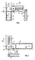
- FIG. 1 schematically illustrates an embodiment of a quick switch in which a compression spring is provided as the spring force accumulator.
- Figure 2 shows an embodiment of the quick switch with a tension spring as a spring force accumulator.
- FIG. 3 An overall representation of a further embodiment of the quick switch is shown in FIG. 3.
- FIG. 4 a quick switch is shown as a section.
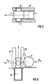
- FIG. 5 schematically illustrates a variant of the embodiment according to FIG. 1 as a top view and in FIG. 6 as a side view.
- a ratchet roller with 2 In the embodiment of a quick-action switch according to FIG. 1 with a roller lock and an elongator for unlocking the spring force accumulator, a ratchet roller with 2, a drive roller with 4, a spring force accumulator with 6, a movable contact with 8, a fixed contact with 9 and an elongator with 10 are designated .
- the direction of movement of the ratchet roller 2 is indicated by an arrow indicated by 12.
- a guide for the movement of the ratchet roller 2 and the drive roller 4 and the socket of the elongator 10 are only indicated as walls in the figure and are designated by 14.
- the drive roller 4 is non-positively connected to the movable contact 8 of the switch, which is only indicated in the figure by a dash-dotted line of action 18.
- the spring force K F of the spring force accumulator 6 is indicated by an arrow in the figure.
- a voltage is applied to the elongator 10 in this working current embodiment in a surge-like manner, ie a voltage with a steep end flank which brings the elongator 10 to charge; the elongator 10 is thereby lengthened by the elongation E, which is shown enlarged in the figure for clarification and in the practical embodiment can be, for example, approximately 50 to 200 ⁇ m.
- the pawl roller 2 is repelled by the force K E and initially overcomes the path s to the unstable position in which the pawl roller 2 and the drive roller 4 in the direction of the spring force K F lie one behind the other.
- the drive roller 4 is moved in the direction of the spring force K F by the force K F of the spring force accumulator 6 and at the same time the ratchet roller is displaced.
- the movable contact 8 of the switch is opened with the movement of the drive roller 4.
- the opening path of the switching contact 8 is approximately as large as the diameter of the ratchet roller 2, for example at least 10 mm.
- the elongator 10 shown schematically in FIG. 1 can be, for example, a piezoelectric elongator that works according to the longitudinal effect and is extended by the predetermined elongation E when a voltage is applied after charging. This extension is used to move the ratchet roller 2 in the direction of arrow 12. If the working voltage on the elongator 6 is interrupted, the elongator is shortened again by the amount of elongation and returns to its original length.
- a magnetostrictive elongator 10 can also be provided, which lengthens when a magnetic field is applied.
- the voltage source for this magnetic field is then switched on.
- the elongator 10 is thus suddenly extended by its elongation E.
- the ratchet roller 2 is moved in the direction of the arrow 12 and the spring force accumulator 6 is triggered and the contact 8 is opened with the movement of the drive roller 4.
- a quiescent current operation of the elongator 10 is provided, which is due to an operating voltage not shown in the figure and is extended by a predetermined elongation E and presses with a sufficient force on the ratchet roller 2, which presses the drive roller 4 in its stable position shown, the cannot be changed by the spring force K F of the spring force accumulator 6.
- the drive roller 4 is located by the path s below its unstable position, in which the ratchet roller 2 and the drive roller 4 are arranged one behind the other in the direction of the force K F of the elongator 10. With the interruption of the voltage applied to the elongator 10, the elongator 10 is discharged.
- the ratchet roller 2 Due to its shortening by the elongation E, which is shown considerably enlarged for clarity in the figure, the ratchet roller 2 is displaced by the lateral component of the spring force K F and the drive roller 4, which is non-positively connected to the movable contact 8 of the switch moved up by the spring force accumulator 6 and the contacts 8 and 9 are opened.
- a comparatively large spring force K F of the spring force accumulator 6 results in a comparatively large path of the drive roller 4 and thus a correspondingly large opening path of the movable contact 8.
- the spring force K F can be approximately a fraction s / d of the blocking force K B, E of the elongator (K F s / d. K B, E ).
- the ratchet roller 2, the drive roller 4 and the elongator 10 are also connected to one another in a non-positive and positive manner.
- the spring force accumulator 6 acts via a shaft 22 and a lever 24, which is rotatably mounted about the axis 26 of the drive roller 4, on a switching shaft 28 for the movable contacts 8 of the quick switch, to which the fixed contacts 9 are assigned.
- the spring force accumulator 6 is also released by shortening the elongator 10 after it has been discharged by interrupting an applied charging voltage.
- the lever 24 thus transmits a corresponding rotary movement to the control shaft 28 and the movable contacts 8 are opened.
- an elongator 10 is also provided, in which the elongator 10 returns to its original length after the interruption of an applied charging voltage, which is indicated in the figure by a negative force K E.
- K E an applied charging voltage
- the drive roller 4 is released and pulled up by the force K F of the spring force accumulator 6.
- a lever 25 is provided which acts directly on the movable contact 8, which bears on the fixed contact 9 in the closed state. It is therefore not a rotational movement, but a tensile force is transmitted from the lever 25 to the movable contact 8.
- the ratchet roller 2 is provided with guide extensions.
- the guidance takes place starting from FIG. 1 through guide walls 15 such that the drive roller 4 can move past the latching point of the latch roller 2.
- the drive path S A of the drive roller 4 can be considerably larger than the diameter D of the ratchet roller 2.
- the force of a spring force accumulator is provided for driving the drive roller 4.
- the driving force can also be supplied by another energy accumulator, for example by a gas pressure accumulator or also by a magnetic energy accumulator that contains a permanent magnet.
Landscapes
- Driving Mechanisms And Operating Circuits Of Arc-Extinguishing High-Tension Switches (AREA)
Applications Claiming Priority (2)
| Application Number | Priority Date | Filing Date | Title |
|---|---|---|---|
| DE3926476 | 1989-08-10 | ||
| DE3926476 | 1989-08-10 |
Publications (2)
| Publication Number | Publication Date |
|---|---|
| EP0412401A2 true EP0412401A2 (fr) | 1991-02-13 |
| EP0412401A3 EP0412401A3 (en) | 1992-01-22 |
Family
ID=6386891
Family Applications (1)
| Application Number | Title | Priority Date | Filing Date |
|---|---|---|---|
| EP19900114614 Withdrawn EP0412401A3 (en) | 1989-08-10 | 1990-07-30 | High-speed circuit breaker |
Country Status (1)
| Country | Link |
|---|---|
| EP (1) | EP0412401A3 (fr) |
Cited By (6)
| Publication number | Priority date | Publication date | Assignee | Title |
|---|---|---|---|---|
| EP0517049A1 (fr) * | 1991-06-03 | 1992-12-09 | ABBPATENT GmbH | Déclencheur à courant de fuite à aimant permanent |
| EP0548732A2 (fr) * | 1991-12-24 | 1993-06-30 | ABBPATENT GmbH | Disjoncteur à courant de défaut |
| EP0548731A2 (fr) * | 1991-12-24 | 1993-06-30 | ABBPATENT GmbH | Disjoncteur à courant de défaut et/ou à courant différentiel |
| DE4443520A1 (de) * | 1994-12-07 | 1996-06-13 | Abb Patent Gmbh | Fehlerstromschutzschalter |
| WO2001050490A1 (fr) * | 1999-12-31 | 2001-07-12 | Abb Service S.R.L. | Interrupteur de puissance |
| DE102016218242A1 (de) | 2016-09-22 | 2018-03-22 | Siemens Aktiengesellschaft | DC-Überspannungsschutz für ein Energiesystem |
Citations (3)
| Publication number | Priority date | Publication date | Assignee | Title |
|---|---|---|---|---|
| CH264733A (de) * | 1948-06-17 | 1949-10-31 | Lindner Karl | Installationsselbstschalter. |
| US2820118A (en) * | 1953-10-02 | 1958-01-14 | Bbc Brown Boveri & Cie | Circuit closer |
| DE1119982B (de) * | 1957-06-08 | 1961-12-21 | Calor Emag Elektrizitaets Ag | Ausloesevorrichtung fuer elektrische Schnellschalter |
-
1990
- 1990-07-30 EP EP19900114614 patent/EP0412401A3/de not_active Withdrawn
Patent Citations (3)
| Publication number | Priority date | Publication date | Assignee | Title |
|---|---|---|---|---|
| CH264733A (de) * | 1948-06-17 | 1949-10-31 | Lindner Karl | Installationsselbstschalter. |
| US2820118A (en) * | 1953-10-02 | 1958-01-14 | Bbc Brown Boveri & Cie | Circuit closer |
| DE1119982B (de) * | 1957-06-08 | 1961-12-21 | Calor Emag Elektrizitaets Ag | Ausloesevorrichtung fuer elektrische Schnellschalter |
Non-Patent Citations (3)
| Title |
|---|
| N.E.C. Research and Development no. 70, Juli 1983, Tokyo, Japan Seite 125 "Tiny Piezo Ceramic Actuators" * |
| Research Disclosure, RD29156, no. 291, Juli 1988, New York, NY, USA Seite 512 "Operating device for circuit breakers" * |
| Richter - v. Voss: "Bauelemente der Feinmechanik" 1949, Verlag Technik Gmbh, Berlin, Deutschland * |
Cited By (8)
| Publication number | Priority date | Publication date | Assignee | Title |
|---|---|---|---|---|
| EP0517049A1 (fr) * | 1991-06-03 | 1992-12-09 | ABBPATENT GmbH | Déclencheur à courant de fuite à aimant permanent |
| EP0548732A2 (fr) * | 1991-12-24 | 1993-06-30 | ABBPATENT GmbH | Disjoncteur à courant de défaut |
| EP0548731A2 (fr) * | 1991-12-24 | 1993-06-30 | ABBPATENT GmbH | Disjoncteur à courant de défaut et/ou à courant différentiel |
| EP0548731A3 (fr) * | 1991-12-24 | 1994-01-26 | Abb Patent Gmbh | |
| EP0548732A3 (fr) * | 1991-12-24 | 1994-01-26 | Abb Patent Gmbh | |
| DE4443520A1 (de) * | 1994-12-07 | 1996-06-13 | Abb Patent Gmbh | Fehlerstromschutzschalter |
| WO2001050490A1 (fr) * | 1999-12-31 | 2001-07-12 | Abb Service S.R.L. | Interrupteur de puissance |
| DE102016218242A1 (de) | 2016-09-22 | 2018-03-22 | Siemens Aktiengesellschaft | DC-Überspannungsschutz für ein Energiesystem |
Also Published As
| Publication number | Publication date |
|---|---|
| EP0412401A3 (en) | 1992-01-22 |
Similar Documents
| Publication | Publication Date | Title |
|---|---|---|
| EP0657326A1 (fr) | Arceau de sécurité pour véhicules automobiles | |
| EP2864995B1 (fr) | Contacteur avec verrou de commutation électromagnétique | |
| DE2728485A1 (de) | Elektromagnetisch betriebene schlagvorrichtung | |
| EP3224851B1 (fr) | Arrangement de déclenchement rapide pour séparation d'un trajet de courant dans un appareil de commutation | |
| EP3284097B1 (fr) | Élément de commutation à fermeture rapide | |
| EP1941525B1 (fr) | Dispositif d' encliquetage pour entrainement a ressort accumulateur | |
| DE2717958A1 (de) | Antriebsvorrichtung fuer elektrische schaltgeraete mit druckkontakten | |
| EP0412401A2 (fr) | Disjoncteur rapide | |
| DE1301181B (de) | Magnetische Betaetigungsvorrichtung | |
| EP0070248B1 (fr) | Sectionneur | |
| WO2001084579A1 (fr) | Declencheur magnetique permettant d'ouvrir un systeme de a contacts | |
| EP3282464B1 (fr) | Mécanisme à ressort et dispositif de commutation comprenant un mécanisme à ressort | |
| DE1120929B (de) | Elektrisches Tuerschloss fuer Kraftfahrzeugtueren, insbesondere Zapfenschloss | |
| DE2914743A1 (de) | Kleinvorrichtung fuer differentialschalter von hoher und hoechster empfindlichkeit, die von mechanisch sehr empfindlichen ausloesern betaetigbar ist | |
| DE1613974A1 (de) | Leistungsschalter | |
| EP0148112A1 (fr) | Interrupteur à déclencheur sélectif | |
| EP1473753A1 (fr) | Appareil de commutation électrique | |
| DE2648468A1 (de) | Schaltgeraet | |
| EP0628977B1 (fr) | Disjoncteur multipolaire | |
| DE2655359C2 (de) | Unterspannungsauslöser für einen elektrischen Schutzschalter | |
| DE1906369A1 (de) | Strombegrenzender Schalter mit Schlaganker | |
| DE954715C (de) | Elektromagnetisch betaetigte Ausloesevorrichtung fuer Schalter, insbesondere Installationsselbstschalter | |
| DE2557223C3 (de) | Elektromagnetische Auslösevorrichtung zur Unterbrechung eines elektrischen Stromkreises | |
| DE3000681A1 (de) | Kontaktbetaetigungsvorrichtung | |
| DE1413901A1 (de) | Schnellschalter mit Lichtbogenloescheinrichtung |
Legal Events
| Date | Code | Title | Description |
|---|---|---|---|
| PUAI | Public reference made under article 153(3) epc to a published international application that has entered the european phase |
Free format text: ORIGINAL CODE: 0009012 |
|
| 17P | Request for examination filed |
Effective date: 19901205 |
|
| AK | Designated contracting states |
Kind code of ref document: A2 Designated state(s): DE GB SE |
|
| PUAL | Search report despatched |
Free format text: ORIGINAL CODE: 0009013 |
|
| AK | Designated contracting states |
Kind code of ref document: A3 Designated state(s): DE GB SE |
|
| STAA | Information on the status of an ep patent application or granted ep patent |
Free format text: STATUS: THE APPLICATION IS DEEMED TO BE WITHDRAWN |
|
| 18D | Application deemed to be withdrawn |
Effective date: 19920723 |