EP0412372B1 - Antriebsvorrichtung für Kraftfahrzeuge - Google Patents
Antriebsvorrichtung für Kraftfahrzeuge Download PDFInfo
- Publication number
- EP0412372B1 EP0412372B1 EP90114430A EP90114430A EP0412372B1 EP 0412372 B1 EP0412372 B1 EP 0412372B1 EP 90114430 A EP90114430 A EP 90114430A EP 90114430 A EP90114430 A EP 90114430A EP 0412372 B1 EP0412372 B1 EP 0412372B1
- Authority
- EP
- European Patent Office
- Prior art keywords
- cardan shaft
- drive mechanism
- drive
- mechanism according
- nominal
- Prior art date
- Legal status (The legal status is an assumption and is not a legal conclusion. Google has not performed a legal analysis and makes no representation as to the accuracy of the status listed.)
- Expired - Lifetime
Links
Images


Classifications
-
- F—MECHANICAL ENGINEERING; LIGHTING; HEATING; WEAPONS; BLASTING
- F16—ENGINEERING ELEMENTS AND UNITS; GENERAL MEASURES FOR PRODUCING AND MAINTAINING EFFECTIVE FUNCTIONING OF MACHINES OR INSTALLATIONS; THERMAL INSULATION IN GENERAL
- F16C—SHAFTS; FLEXIBLE SHAFTS; ELEMENTS OR CRANKSHAFT MECHANISMS; ROTARY BODIES OTHER THAN GEARING ELEMENTS; BEARINGS
- F16C3/00—Shafts; Axles; Cranks; Eccentrics
- F16C3/02—Shafts; Axles
- F16C3/026—Shafts made of fibre reinforced resin
-
- B—PERFORMING OPERATIONS; TRANSPORTING
- B60—VEHICLES IN GENERAL
- B60K—ARRANGEMENT OR MOUNTING OF PROPULSION UNITS OR OF TRANSMISSIONS IN VEHICLES; ARRANGEMENT OR MOUNTING OF PLURAL DIVERSE PRIME-MOVERS IN VEHICLES; AUXILIARY DRIVES FOR VEHICLES; INSTRUMENTATION OR DASHBOARDS FOR VEHICLES; ARRANGEMENTS IN CONNECTION WITH COOLING, AIR INTAKE, GAS EXHAUST OR FUEL SUPPLY OF PROPULSION UNITS IN VEHICLES
- B60K17/00—Arrangement or mounting of transmissions in vehicles
- B60K17/22—Arrangement or mounting of transmissions in vehicles characterised by arrangement, location, or type of main drive shafting, e.g. cardan shaft
-
- B—PERFORMING OPERATIONS; TRANSPORTING
- B60—VEHICLES IN GENERAL
- B60R—VEHICLES, VEHICLE FITTINGS, OR VEHICLE PARTS, NOT OTHERWISE PROVIDED FOR
- B60R19/00—Wheel guards; Radiator guards, e.g. grilles; Obstruction removers; Fittings damping bouncing force in collisions
-
- F—MECHANICAL ENGINEERING; LIGHTING; HEATING; WEAPONS; BLASTING
- F16—ENGINEERING ELEMENTS AND UNITS; GENERAL MEASURES FOR PRODUCING AND MAINTAINING EFFECTIVE FUNCTIONING OF MACHINES OR INSTALLATIONS; THERMAL INSULATION IN GENERAL
- F16D—COUPLINGS FOR TRANSMITTING ROTATION; CLUTCHES; BRAKES
- F16D9/00—Couplings with safety member for disconnecting, e.g. breaking or melting member
-
- B—PERFORMING OPERATIONS; TRANSPORTING
- B60—VEHICLES IN GENERAL
- B60R—VEHICLES, VEHICLE FITTINGS, OR VEHICLE PARTS, NOT OTHERWISE PROVIDED FOR
- B60R19/00—Wheel guards; Radiator guards, e.g. grilles; Obstruction removers; Fittings damping bouncing force in collisions
- B60R2019/007—Means for adjusting or regulating the crash absorption capacity of the vehicle, e.g. when detecting an impending collision
-
- F—MECHANICAL ENGINEERING; LIGHTING; HEATING; WEAPONS; BLASTING
- F16—ENGINEERING ELEMENTS AND UNITS; GENERAL MEASURES FOR PRODUCING AND MAINTAINING EFFECTIVE FUNCTIONING OF MACHINES OR INSTALLATIONS; THERMAL INSULATION IN GENERAL
- F16C—SHAFTS; FLEXIBLE SHAFTS; ELEMENTS OR CRANKSHAFT MECHANISMS; ROTARY BODIES OTHER THAN GEARING ELEMENTS; BEARINGS
- F16C2326/00—Articles relating to transporting
- F16C2326/01—Parts of vehicles in general
- F16C2326/06—Drive shafts
Definitions
- the invention relates to a drive device for motor vehicles, especially for cars, according to. the preamble of claim 1.
- the body, the arrangement of the drive units and the safety devices are designed such that, for example in the event of frontal crashes, certain acceleration values in the millisecond range are not exceeded for the occupants.
- the drive device it is known (DE 2156783A1) to design the cardan shaft leading from the drive unit in the front region to the rear to the differential or rear region with a deformation element in order to also destroy or reduce impact energy.
- cardan shaft since the cardan shaft must transmit a maximum torsional moment and the deformability is also limited by the required bending strength and rigidity (natural frequency), relatively high dynamic axial forces can still be transmitted, which can have a negative impact on the acceleration values in the event of a crash. This also applies to cardan shafts made of fiber composite material, as specified, for example, by EP 19585A1.
- the object of the invention is to design the generic drive device so that the impact on the acceleration values in crashes is reduced while maintaining a robust, reliable construction.
- the axial force that can still be transmitted can, for example, be set to a value which occurs in a frontal crash at a motor vehicle speed of 15 km / h; with higher axial forces, the cardan shaft is destroyed and must be replaced when the motor vehicle is repaired.
- an explosive device can be incorporated into the cardan shaft made of fiber composite material, which is ignited when the defined axial force occurs.
- This ignition can particularly advantageously be synchronized with the ignition of an airbag as passive occupant protection.
- the explosive device can be arranged, for example, inside the cardan shaft or can be integrated or wrapped directly in the cardan shaft during its manufacture.
- the cardan shaft from fiber composite material so that the ratio between the statically transferable torsional moment and the axially directed dynamic breaking force is between 10 to 12.5, the torsional moment in Nm and the breaking force in KN.
- both the maximum torsional moment occurring can be transmitted and nevertheless destruction occurs with a defined dynamic axial force.
- the dynamic axial force in this design is such that both the maximum component load under climatic conditions and over their entire required service life is ensured, as well as a significant reduction in the occupant acceleration values is achieved in the event of a crash by destruction of the cardan shaft or abrupt reduction of the dynamic axial force towards zero. It also ensures that the propeller shaft is not damaged in a crash below a defined speed (eg below 15 km / h).
- FIG. 1 shows a drive device in a passenger car (passenger car) with a drive unit 10, which is composed of an internal combustion engine 12, a front differential 14 for driving the front wheels and a speed change gear 16.
- the rear wheels of the car are driven via a cardan shaft 18 and a rear differential 20.
- the drive unit 10, the propeller shaft 18 at 22 and the rear differential 20 are hung or mounted on the body of the car in a manner not shown in a vibration-isolated manner.
- the cardan shaft 18 is composed of a front cardan shaft 24 and a rear cardan shaft 26 and has two connecting flanges 28, 30 and an articulated connection 32. While the rear cardan shaft 26 as well as the connecting flanges and the articulated connection are conventionally made of steel, the front cardan shaft 24 consists of an epoxy resin matrix in which glass fibers are embedded in a winding angle of +/- 20 °.
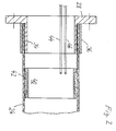
- connection between the connecting flange 28 and the tubular cardan shaft 24 can be made by pressing in the free neck 34, an outer steel ring 36 supporting the peripheral forces acting on the cardan shaft 24.
- a cardan shaft 24 with a cross-sectionally U-shaped steel ring 40 is glued into it, in whose annular space delimited by the inner circumference of the cardan shaft 24, an explosive powder 42 is embedded.
- the explosive device 40, 42 can be ignited via electrical lines 44, 46 and is designed with regard to its explosive effect in such a way that the cardan shaft 24 is destroyed in the immediate circumferential area if it is ignited.
- the lines 44, 46 are connected to a control device 50 via a sliding contact device 48 arranged at the output of the change gear 16 and via electrical lines, not shown Impact sensors, not shown, controls the ignition of an airbag, also not shown, as a passive safety device for the car.
- the control unit 50 is designed such that when the airbag is ignited (inflated), the explosive device 40, 42 is also ignited and the cardan shaft 24 is destroyed at the same time.
- Fig. 3 shows a portion of a propeller shaft 24 ', which may be constructed similarly to the propeller shaft 24 shown in FIGS. 1 and 2 beyond the scope explained below.
- the cardan shaft 24 ' consists of an epoxy resin matrix, in the high tensile (HT grade) carbon fibers 52 are embedded in a winding angle ⁇ to the longitudinal axis of the cardan shaft 24' of +/- 15 °.
- the inside diameter d i is 70 mm and the wall thickness s is 2.5 mm.
- the ratio d i to s 28.
- This cardan shaft 24 ' which is only one exemplary embodiment, transmits the required maximum torsional moment Md T in the static and dynamic range, taking into account the possible climatic conditions in cars (temperature, humidity, etc.), withstands the usual abuses (frontal crash ⁇ 15 km / h), still has a satisfactory bending stiffness (natural frequency) and especially for cars with a total weight of approx.1,800 kg (mass!) it fulfills the requirement that destruction occurs from the defined dynamic axial force, which suddenly reduces the axial support force (reaction force) towards zero .
Landscapes
- Engineering & Computer Science (AREA)
- Mechanical Engineering (AREA)
- General Engineering & Computer Science (AREA)
- Ocean & Marine Engineering (AREA)
- Chemical & Material Sciences (AREA)
- Combustion & Propulsion (AREA)
- Transportation (AREA)
- Shafts, Cranks, Connecting Bars, And Related Bearings (AREA)
- Motor Power Transmission Devices (AREA)
Applications Claiming Priority (2)
| Application Number | Priority Date | Filing Date | Title |
|---|---|---|---|
| DE3926427A DE3926427C1 (enExample) | 1989-08-10 | 1989-08-10 | |
| DE3926427 | 1989-08-10 |
Publications (2)
| Publication Number | Publication Date |
|---|---|
| EP0412372A1 EP0412372A1 (de) | 1991-02-13 |
| EP0412372B1 true EP0412372B1 (de) | 1992-12-30 |
Family
ID=6386857
Family Applications (1)
| Application Number | Title | Priority Date | Filing Date |
|---|---|---|---|
| EP90114430A Expired - Lifetime EP0412372B1 (de) | 1989-08-10 | 1990-07-27 | Antriebsvorrichtung für Kraftfahrzeuge |
Country Status (3)
| Country | Link |
|---|---|
| EP (1) | EP0412372B1 (enExample) |
| DE (2) | DE3926427C1 (enExample) |
| ES (1) | ES2036874T3 (enExample) |
Families Citing this family (6)
| Publication number | Priority date | Publication date | Assignee | Title |
|---|---|---|---|---|
| DE69304689T2 (de) * | 1992-04-24 | 1997-04-30 | United Technologies Corp | Verbinden von thermoplastischen und wärmehärtenden verbundstrukturen mit metallischen strukturen |
| RU2180291C2 (ru) * | 1999-12-14 | 2002-03-10 | Оао "Камаз" | Укороченный раздвижной карданный вал |
| RU2212345C1 (ru) * | 2002-04-01 | 2003-09-20 | Открытое акционерное общество "Белкард" | Карданный вал наземных транспортных средств |
| DE10251776B3 (de) * | 2002-11-07 | 2004-06-09 | Daimlerchrysler Ag | Vorrichtung zum Abtrennen der Gelenkwelle vom Rohbau und zum insassenunschädlichen Ausknicken der Gelenkwelle beim Frontalaufprall |
| DE102009009688A1 (de) * | 2009-02-19 | 2010-08-26 | Bayerische Motoren Werke Aktiengesellschaft | Antriebsstrang für Fahrzeuge |
| DE102013204181A1 (de) * | 2013-03-12 | 2014-09-18 | Bayerische Motoren Werke Aktiengesellschaft | Anschlussvorrichtung für eine Welle |
Family Cites Families (8)
| Publication number | Priority date | Publication date | Assignee | Title |
|---|---|---|---|---|
| DE1231494B (de) * | 1965-04-28 | 1966-12-29 | Bbc Brown Boveri & Cie | Sicherheitskupplung |
| DE6802244U (de) * | 1968-01-22 | 1969-02-27 | Ara Inc | Energieabsorbierende, teleskopartige rohrfoermige teile mit der faehigkeit zur uebertragung von drehmomenten. |
| DE2149091A1 (de) * | 1971-10-01 | 1973-04-05 | Daimler Benz Ag | Gelenkwelle fuer fahrzeuge, insbesondere fuer kraftfahrzeuge |
| DE2156783C3 (de) * | 1971-11-16 | 1981-02-05 | Daimler-Benz Ag, 7000 Stuttgart | Antriebsstrang für Kraftfahrzeuge |
| US4089190A (en) * | 1976-04-14 | 1978-05-16 | Union Carbide Corporation | Carbon fiber drive shaft |
| JPS55149437A (en) * | 1979-05-10 | 1980-11-20 | Ciba Geigy Ag | Transmission shaft |
| DE3139247A1 (de) * | 1980-10-06 | 1982-07-22 | Celanese Corp., 10036 New York, N.Y. | Kardangelenk-wellenkupplungen entbehrlich machende zusammengesetzte fahrzeug-antriebswelle |
| GB2200488A (en) * | 1987-01-31 | 1988-08-03 | Ford Motor Co | A steering column arrangement in a motor vehicle |
-
1989
- 1989-08-10 DE DE3926427A patent/DE3926427C1/de not_active Expired - Lifetime
-
1990
- 1990-07-27 DE DE9090114430T patent/DE59000688D1/de not_active Expired - Fee Related
- 1990-07-27 EP EP90114430A patent/EP0412372B1/de not_active Expired - Lifetime
- 1990-07-27 ES ES199090114430T patent/ES2036874T3/es not_active Expired - Lifetime
Also Published As
| Publication number | Publication date |
|---|---|
| DE3926427C1 (enExample) | 1990-12-20 |
| EP0412372A1 (de) | 1991-02-13 |
| ES2036874T3 (es) | 1993-06-01 |
| DE59000688D1 (de) | 1993-02-11 |
Similar Documents
| Publication | Publication Date | Title |
|---|---|---|
| US5118214A (en) | Connecting assembly | |
| DE3337232C2 (enExample) | ||
| EP0804352B1 (de) | Sicherheitsanordnung für ein kraftfahrzeug | |
| EP2563625B1 (de) | Straffervorrichtung für einen sicherheitsgurt | |
| DE10113098B4 (de) | Sicherheitseinrichtung an einem Fahrzeug zum Schutz von Fahrzeuginsassen bei einer Frontalkollision | |
| DE19515852A1 (de) | Betätigungsanordnung für ein Kraftfahrzeug | |
| WO1985001709A1 (fr) | Dispositif de securite pour vehicule | |
| DE102004036332B4 (de) | Kraftfahrzeug | |
| EP0412372B1 (de) | Antriebsvorrichtung für Kraftfahrzeuge | |
| DE19627061A1 (de) | Deformationselement | |
| DE2241651A1 (de) | Personenkraftwagen | |
| EP0748734B1 (de) | Lenksäule für Kraftfahrzeuge | |
| DE102017100356A1 (de) | Wellenverbindung | |
| DE102019006731A1 (de) | Vorbaukarosseriestruktur eines Kraftfahrzeugs sowie Kraftfahrzeug | |
| DE3920793A1 (de) | Verbindungsanordnung | |
| DE19704013C2 (de) | Sicherheitslenksäule | |
| DE10032711C2 (de) | Teilbare Spurstange für Kraftfahrzeuge | |
| EP1113955B1 (de) | Lenkspindel | |
| DE102011082146A1 (de) | Pedalanordnung mit Sicherheitseinrichtung | |
| DE69920242T2 (de) | Fahrzeugarmaturenbrettanordnung | |
| DE19962550B4 (de) | Sicherheitsvorrichtung für ein Kraftfahrzeug | |
| DE102024110174B3 (de) | Hohlträger für einen Rohbau eines Kraftfahrzeugs | |
| DE10251776B3 (de) | Vorrichtung zum Abtrennen der Gelenkwelle vom Rohbau und zum insassenunschädlichen Ausknicken der Gelenkwelle beim Frontalaufprall | |
| DE4005259A1 (de) | Lenkung fuer kraftfahrzeuge | |
| DE212018000306U1 (de) | Bei einem Aufprall kollabierbare Gelenkwellenbaugruppe |
Legal Events
| Date | Code | Title | Description |
|---|---|---|---|
| PUAI | Public reference made under article 153(3) epc to a published international application that has entered the european phase |
Free format text: ORIGINAL CODE: 0009012 |
|
| 17P | Request for examination filed |
Effective date: 19900727 |
|
| AK | Designated contracting states |
Kind code of ref document: A1 Designated state(s): DE ES FR GB IT |
|
| 17Q | First examination report despatched |
Effective date: 19920228 |
|
| ITF | It: translation for a ep patent filed | ||
| GRAA | (expected) grant |
Free format text: ORIGINAL CODE: 0009210 |
|
| AK | Designated contracting states |
Kind code of ref document: B1 Designated state(s): DE ES FR GB IT |
|
| ET | Fr: translation filed | ||
| REF | Corresponds to: |
Ref document number: 59000688 Country of ref document: DE Date of ref document: 19930211 |
|
| GBT | Gb: translation of ep patent filed (gb section 77(6)(a)/1977) |
Effective date: 19930210 |
|
| REG | Reference to a national code |
Ref country code: ES Ref legal event code: FG2A Ref document number: 2036874 Country of ref document: ES Kind code of ref document: T3 |
|
| PLBE | No opposition filed within time limit |
Free format text: ORIGINAL CODE: 0009261 |
|
| STAA | Information on the status of an ep patent application or granted ep patent |
Free format text: STATUS: NO OPPOSITION FILED WITHIN TIME LIMIT |
|
| 26N | No opposition filed | ||
| PGFP | Annual fee paid to national office [announced via postgrant information from national office to epo] |
Ref country code: FR Payment date: 19980717 Year of fee payment: 9 |
|
| PGFP | Annual fee paid to national office [announced via postgrant information from national office to epo] |
Ref country code: GB Payment date: 19990621 Year of fee payment: 10 |
|
| PGFP | Annual fee paid to national office [announced via postgrant information from national office to epo] |
Ref country code: ES Payment date: 19990709 Year of fee payment: 10 Ref country code: DE Payment date: 19990709 Year of fee payment: 10 |
|
| PG25 | Lapsed in a contracting state [announced via postgrant information from national office to epo] |
Ref country code: FR Free format text: THE PATENT HAS BEEN ANNULLED BY A DECISION OF A NATIONAL AUTHORITY Effective date: 19990731 |
|
| REG | Reference to a national code |
Ref country code: FR Ref legal event code: ST |
|
| PG25 | Lapsed in a contracting state [announced via postgrant information from national office to epo] |
Ref country code: GB Free format text: LAPSE BECAUSE OF NON-PAYMENT OF DUE FEES Effective date: 20000727 |
|
| PG25 | Lapsed in a contracting state [announced via postgrant information from national office to epo] |
Ref country code: ES Free format text: LAPSE BECAUSE OF NON-PAYMENT OF DUE FEES Effective date: 20000728 |
|
| GBPC | Gb: european patent ceased through non-payment of renewal fee |
Effective date: 20000727 |
|
| PG25 | Lapsed in a contracting state [announced via postgrant information from national office to epo] |
Ref country code: DE Free format text: LAPSE BECAUSE OF NON-PAYMENT OF DUE FEES Effective date: 20010501 |
|
| REG | Reference to a national code |
Ref country code: ES Ref legal event code: FD2A Effective date: 20010810 |
|
| PG25 | Lapsed in a contracting state [announced via postgrant information from national office to epo] |
Ref country code: IT Free format text: LAPSE BECAUSE OF NON-PAYMENT OF DUE FEES;WARNING: LAPSES OF ITALIAN PATENTS WITH EFFECTIVE DATE BEFORE 2007 MAY HAVE OCCURRED AT ANY TIME BEFORE 2007. THE CORRECT EFFECTIVE DATE MAY BE DIFFERENT FROM THE ONE RECORDED. Effective date: 20050727 |