EP0411888A2 - Elektrischer Steckverbinder - Google Patents
Elektrischer Steckverbinder Download PDFInfo
- Publication number
- EP0411888A2 EP0411888A2 EP90308392A EP90308392A EP0411888A2 EP 0411888 A2 EP0411888 A2 EP 0411888A2 EP 90308392 A EP90308392 A EP 90308392A EP 90308392 A EP90308392 A EP 90308392A EP 0411888 A2 EP0411888 A2 EP 0411888A2
- Authority
- EP
- European Patent Office
- Prior art keywords
- section
- electrical connector
- contact
- housing
- passageway
- Prior art date
- Legal status (The legal status is an assumption and is not a legal conclusion. Google has not performed a legal analysis and makes no representation as to the accuracy of the status listed.)
- Granted
Links
Images

Classifications
-
- H—ELECTRICITY
- H01—ELECTRIC ELEMENTS
- H01R—ELECTRICALLY-CONDUCTIVE CONNECTIONS; STRUCTURAL ASSOCIATIONS OF A PLURALITY OF MUTUALLY-INSULATED ELECTRICAL CONNECTING ELEMENTS; COUPLING DEVICES; CURRENT COLLECTORS
- H01R13/00—Details of coupling devices of the kinds covered by groups H01R12/70 or H01R24/00 - H01R33/00
- H01R13/02—Contact members
- H01R13/10—Sockets for co-operation with pins or blades
- H01R13/11—Resilient sockets
-
- H—ELECTRICITY
- H01—ELECTRIC ELEMENTS
- H01R—ELECTRICALLY-CONDUCTIVE CONNECTIONS; STRUCTURAL ASSOCIATIONS OF A PLURALITY OF MUTUALLY-INSULATED ELECTRICAL CONNECTING ELEMENTS; COUPLING DEVICES; CURRENT COLLECTORS
- H01R12/00—Structural associations of a plurality of mutually-insulated electrical connecting elements, specially adapted for printed circuits, e.g. printed circuit boards [PCB], flat or ribbon cables, or like generally planar structures, e.g. terminal strips, terminal blocks; Coupling devices specially adapted for printed circuits, flat or ribbon cables, or like generally planar structures; Terminals specially adapted for contact with, or insertion into, printed circuits, flat or ribbon cables, or like generally planar structures
- H01R12/70—Coupling devices
- H01R12/71—Coupling devices for rigid printing circuits or like structures
- H01R12/712—Coupling devices for rigid printing circuits or like structures co-operating with the surface of the printed circuit or with a coupling device exclusively provided on the surface of the printed circuit
Definitions
- the present invention relates to an electrical connector comprising a male plug and a female socket, and more particularly to a female socket having a plurality of terminals each comprised of a contact section into which a male pin is to be inserted, a solder tail section which is to be soldered to a printed circuit board, and a force absorbing intermediate joint, the opposite ends of which are integrally connected to said contact section and said solder tail section.
- two printed circuit boards can be electrically connected by an electrical connector assembly in which a male plug is mounted to one printed circuit board and a female socket is mounted to the other printed circuit board.
- the female socket has a plurality of female terminals, each being comprised of a contact section, a solder tail section and an intermediate section.
- the contact section is designed to permit the insertion of a male pin.
- the solder tail section is designed to be inserted into a hole in a printed circuit board and soldered to the printed circuit board.
- the prior art electrical connector has long been used and is satisfactory for many uses. Under some circumstances, however, its performance is not satisfactory. For example, if the male terminals of a male plug which is attached to a printed board are inserted into the female terminals of a female socket which is attached to another printed board, the socket housing will be permitted to move back and forth. Because of this movement and because of the shape of the intermediate section, the force that is applied to the contact section while inserting the pin terminal into the female terminal will be applied directly to the solder tail section of the female terminal. The consequence of this force may be that the solder tail section of the female terminal is partly deformed, the part of circuit pattern to which the solder tail section is soldered is peeled off, or cracks may appear in the solder of the female terminal. The greater the density on the printed circuit board, the more likely these problems will occur because a high density package requires the use of terminals of the minimum possible size, which are inevitably fragile.
- One object of the present invention is to provide an electrical connector that is capable of absorbing an external force applied to the contact section of each female terminal in the direction in which a male pin terminal is inserted into the contact section of the female terminal. This will isolate the solder tail section from this force and thus prevent deformation of the solder section, peeling-off or cracking of the solder of the female terminal, which may lead to an incomplete electrical connection.
- Another object of the present invention is to provide an electrical connector which has means to prevent perpetual deformation of the intermediate joint section of each female terminal beyond recoverable deformation limits, thus assuring that each female terminal retains its force-absorbing capability for an extended time even upon the occurrence of repeated vigorous coupling and decoupling of the male and female terminals.
- an electrical connector comprising a male plug and a female socket, said male plug having a plurality of male terminals mounted in its housing, and said female socket having a plurality of female terminals each comprised of a contact section, a solder tail section and an intermediate joint section integrally connected at its opposite ends to said contact section and said solder tail section.
- the contact section is mounted to a first housing
- the solder tail section is mounted to a second housing.
- the intermediate joint of said female terminal is of such a curved shape that it provides enough resiliency to absorb external forces applied to said female terminal in the direction in which a pin terminal is inserted in said contact section of said female terminal.
- the first and second housings have projections from their opposed walls that create a gap whereby said intermediate joint of each female terminal is prevented from being deformed beyond its recoverable deformation limit due to said projections abutting against each other.
- the intermediate joint may be in the shape of "U" and may be flexible in directions perpendicular to the direction in which a pin terminal is inserted in the contact section, and the first housing may have a longitudinal opening elongated in the direction perpendicular to the direction in which the pin terminal is inserted in the contact section.
- the female socket is attached to a printed circuit board with the first housing somewhat loosely fixed to the printed circuit board to permit the first housing to move back and forth slightly
- an external force will be directed to the contact section in the direction in which the male pin terminal is inserted.
- the curved intermediate joint will be yieldingly bent to substantially absorb the external force, thereby minimizing the external force applied to the solder tail section. As a result, peeling-off or cracking of the solder will be minimized.
- the distance between the opposed projections of the first and second housings is determined so as to prevent the bending of the curved intermediate joint beyond its recoverable deformation limit even if a strong pin-insertion force is applied to the contact section. Thus, no perpetual deformation will result to the curved intermediate joint.
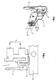
- Figs. 1 to 5 show a female terminal indicated generally at 1 which is used in an electrical connector according to the present invention.
- Female terminal 1 is made from a thin metal sheet of good conductivity. In known manner, a terminal pattern is stamped out from a metal sheet (Fig. 2) and is folded into a female terminal structure 1.
- Such structure comprises contact section 2 having parallel-spaced, opposite contact pieces 2a and 2b; solder tail section 3; and curved intermediate joint section 4 whose opposite ends are integrally connected to contact section 2 and solder tail section 3.
- intermediate joint 4 is shaped in the letter “U” having gap 5 between its opposite legs.
- "U"-shaped joint 4 is dimensioned so that upon inserting male terminal 18 into female terminal 1 (Fig. 10), "U"-shaped joint 4 yieldingly deforms to absorb a portion of the external force in the direction Z.
- "U"-shaped joint 4 functions as a resilient deformation area to absorb a portion of an external force and prevent the force from being transferred to solder tail section 3, effectively isolating solder tail 3 from the insertion force.
- intermediate joint 4 can take a different shape such as in the shape of the letters "V", "W” or "M”, so long as the shape will absorb a portion of the insertion force in order to isolate the solder tail section 3.
- Fig. 2 shows a terminal pattern which is stamped out of a thin metal sheet.
- a plurality of terminal patterns are integrally connected to carrier band 6.
- Each pattern is folded into a female terminal in known manner. Because the terminals are made of thin metal sheet, the curved joint 4 of the female terminal 1 is easily bendable in a direction S (Figs. 1 and 4) perpendicular to the direction Z in which a pin terminal is inserted into female terminal 1.
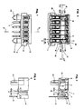
- Figs. 6-10 show female terminals inserted into a female socket housing.
- Contact section 2 of each female terminal 1 is fitted in first housing 8 of the socket, and is oriented with respect to pin-insertion aperture 13 of first housing 8 to allow a pin terminal to be inserted into contact section 2 of female terminal 1.
- Solder tail section 3 of female terminal 1 is fitted in second housing 9, allowing part of the tail section to appear from the bottom surface of second housing 9.
- Intermediate joint 4 of female terminal 1 is exposed between first and second housings 8 and 9 of the socket.
- the resilient, force-absorbing "U"-shaped section 4 of each female terminal is between first and second housing 8 and 9.
- "U"-shaped section 4 can be yieldingly deformed when an external force is applied to female terminal 1 upon insertion of pin terminal 18 therein, and will return to its initial, stress-free position when the external force is removed. To assure such performance it is necessary to prevent the intermediate joint 4 from being deformed beyond its recoverable deformation limit.
- two projections 10a and 10b (Fig. 6) are integrally connected to rear surface 15 of first housing 8.
- the rear surface 15 faces the front surface 16 of second housing 9.
- Two projections 11a and 11b are integrally connected to front surface 16 of second housing 9.
- projection 10a faces projection 11a, leaving gap 12 therebetween and projection 10b faces projection 11b, leaving gap 12 therebetween.
- the gap 12 is dimensioned so that 10a and 11a, and 10b and 11b, will contact each other prior to over-stressing curved joint 4.
- each projection has an angled surface.
- First housing 8 has elongate pin receiving slot 13 positioned in the direction J perpendicular to the direction Z in which a pin terminal 18 is inserted into the female terminal 1. Both slot 13 and contact section 2 may be dimensioned in direction J substantially greater than pin terminal 18. Thus, even if a male plug is attached to a printed board somewhat inexactly in the direction J, the dimensions of elongated slot 13 and contact section 2 will permit insertion of male terminal 18 into contact section 2 of female terminal 1. Due to its shape and size, female terminal 1 is capable of yieldingly deforming at its joint section 4 in the direction Z, and of bending in directions S and J
- first housing 8 has stopper 14 extending down from its bottom.
- Aperture 19 in printed circuit board 17 is made somewhat larger than the diameter of stopper 14, thereby permitting positional adjustment of first housing 8.
- the female socket is attached to printed board 17. Specifically, stopper 19 of first housing 8 is pushed into aperture 19, and solder tail section 3 of each female terminal is soldered to the circuit pattern of printed board 17 (Fig. 10).
- the male plug may be attached to another printed circuit board or another device or cable. Each male terminal 18 is inserted into contact section 2 of female terminal 1, thus completing the electrical connection therebetween.
- a male plug and/or a female socket may be attached to associated printed circuit boards somewhat aside from the exact position, for example, along the direction S.
- the "U"-shaped joint 4 is also flexible enough in lateral direction S to permit positional adjustment of female terminal 1 with respect to male terminal 18.
- Elongated slot 13 of first housing 8 is dimensioned so that female terminal 2 can move slightly within slot 13.
- This feature combined with the movable mounting of first housing 8 with respect to printed circuit board 17 permit positional adjustment of female terminals 1 with respect to male terminals 18, thereby permitting the male and female terminals to mate with each other irrespective of deviation of the male plug and/or female socket from their exact positions.
- the connector of the present invention not only isolates solder tail 3 from insertion forces, but also permits contact 2 to "float" sufficiently to permit proper mating of pin 18 and contact 2 even if the female terminal 1 or male pin 18 are imprecisely positioned.
Applications Claiming Priority (2)
| Application Number | Priority Date | Filing Date | Title |
|---|---|---|---|
| JP90903/89 | 1989-08-01 | ||
| JP1989090903U JPH0338769Y2 (de) | 1989-08-01 | 1989-08-01 |
Publications (3)
| Publication Number | Publication Date |
|---|---|
| EP0411888A2 true EP0411888A2 (de) | 1991-02-06 |
| EP0411888A3 EP0411888A3 (en) | 1991-04-10 |
| EP0411888B1 EP0411888B1 (de) | 1995-02-15 |
Family
ID=14011364
Family Applications (1)
| Application Number | Title | Priority Date | Filing Date |
|---|---|---|---|
| EP90308392A Expired - Lifetime EP0411888B1 (de) | 1989-08-01 | 1990-07-31 | Elektrischer Steckverbinder |
Country Status (4)
| Country | Link |
|---|---|
| US (1) | US5112235A (de) |
| EP (1) | EP0411888B1 (de) |
| JP (1) | JPH0338769Y2 (de) |
| DE (1) | DE69016871T2 (de) |
Cited By (13)
| Publication number | Priority date | Publication date | Assignee | Title |
|---|---|---|---|---|
| EP0598336A2 (de) * | 1992-11-19 | 1994-05-25 | Molex Incorporated | Elektrischer Verbinder zum Verbinden von Leiterplatten |
| WO1995004388A1 (en) * | 1993-07-28 | 1995-02-09 | Litton Systems, Inc. | Electrical connector terminal |
| EP0678936A1 (de) * | 1994-04-22 | 1995-10-25 | The Whitaker Corporation | Miniatür reibkorrosionsfreie Steckbuchse |
| DE19648277A1 (de) * | 1996-11-21 | 1998-05-28 | Whitaker Corp | Elektrische Anschlußklemme |
| EP0848455A2 (de) * | 1994-01-25 | 1998-06-17 | The Whitaker Corporation | Elektrischer Verbinder |
| EP0903817A1 (de) * | 1997-09-17 | 1999-03-24 | Japan Solderless Terminal Mfg Co Ltd | Verfahren zum Einsetzen von elektrischen Kontakten in einem Verbindergehäuse |
| DE19805708A1 (de) * | 1998-02-12 | 1999-09-09 | Siemens Ag | Steckvorrichtung |
| EP1005109A2 (de) * | 1998-11-24 | 2000-05-31 | Sumitomo Electric Industries, Ltd. | Elektronische Steuereinheit mit elektrischem Verbinder |
| EP1160925A2 (de) * | 2000-05-31 | 2001-12-05 | WABCO GmbH & Co. OHG | Elektrischer Steckkontakt |
| WO2005088774A1 (en) * | 2004-03-09 | 2005-09-22 | 3M Innovative Properties Company | Deformable terminal and a strobe light unit that includes the terminal |
| DE102004050715B3 (de) * | 2004-10-19 | 2006-03-09 | Küster Automotive Door Systems GmbH | Kontaktelement zur elektrischen Kontaktierung zweier Anschlüsse |
| WO2010142477A1 (de) * | 2009-06-08 | 2010-12-16 | Robert Bosch Gmbh | Anschlusselement und zugehöriges fluidbaugruppe |
| WO2011110688A1 (de) * | 2010-03-12 | 2011-09-15 | Phoenix Contact Gmbh & Co. Kg | Steckverbinder |
Families Citing this family (32)
| Publication number | Priority date | Publication date | Assignee | Title |
|---|---|---|---|---|
| JP2552225B2 (ja) * | 1992-07-16 | 1996-11-06 | モレックス インコーポレーテッド | フローティングタイプの電気コネクタ |
| US5498167A (en) * | 1994-04-13 | 1996-03-12 | Molex Incorporated | Board to board electrical connectors |
| US5494456A (en) * | 1994-10-03 | 1996-02-27 | Methode Electronics, Inc. | Wire-trap connector with anti-overstress member |
| US5520551A (en) * | 1994-12-01 | 1996-05-28 | The Whitaker Corporation | Molded latching apparatus for printed circuit mounted components |
| GB9425740D0 (en) * | 1994-12-20 | 1995-02-22 | Amp Gmbh | Anti-fretting terminal for PCB |
| US5613877A (en) * | 1995-11-02 | 1997-03-25 | Molex Incorporated | Electric connector boardlock |
| US5697812A (en) * | 1996-06-14 | 1997-12-16 | Molex Incorporated | Board-mounted electrical connector |
| US5885092A (en) * | 1996-06-21 | 1999-03-23 | Molex Incorporated | Electric connector assembly with improved registration characteristics |
| JP3116300B2 (ja) * | 1996-06-21 | 2000-12-11 | モレックス インコーポレーテッド | プリント回路基板用コネクタ |
| US6062889A (en) * | 1997-01-13 | 2000-05-16 | The Whitaker Corporation | Module connector having a switching mechanism |
| JPH10241807A (ja) * | 1997-02-14 | 1998-09-11 | Molex Inc | 電気コネクタ |
| US6007375A (en) * | 1997-09-05 | 1999-12-28 | Molex Incorporated | Mounting system for an electrical connector assembly |
| JPH11111407A (ja) * | 1997-10-03 | 1999-04-23 | Fujitsu Ltd | コネクタの表面実装方法およびコネクタ |
| US5980314A (en) * | 1998-03-13 | 1999-11-09 | Molex Incorporated | Electrical connector with improved board mounting peg |
| DE20004338U1 (de) * | 2000-03-08 | 2001-07-19 | Bosch Gmbh Robert | Einschubmodul für Verstellmotoren |
| US6979215B2 (en) | 2001-11-28 | 2005-12-27 | Molex Incorporated | High-density connector assembly with flexural capabilities |
| US6884974B2 (en) * | 2003-03-21 | 2005-04-26 | Tutco, Inc. | Mica board electrical resistance wire heater, subassemblies, components, and methods of assembly |
| JP4455104B2 (ja) * | 2004-03-12 | 2010-04-21 | 株式会社エルモ社 | スナップフィット結合 |
| ATE389960T1 (de) * | 2004-06-30 | 2008-04-15 | Tyco Electronics Nederland Bv | Verbinder für elektronische bauteile |
| JP4951306B2 (ja) * | 2006-10-13 | 2012-06-13 | タイコエレクトロニクスジャパン合同会社 | コンタクトおよび電気コネクタ |
| CN101606304B (zh) * | 2007-02-19 | 2012-05-09 | 三菱电机株式会社 | 电动机的端子构造 |
| DE102007058243A1 (de) * | 2007-12-04 | 2009-06-10 | Robert Bosch Gmbh | Anschlusselement und zugehöriges Fluidbaugruppe |
| JP5227645B2 (ja) * | 2008-04-21 | 2013-07-03 | 矢崎総業株式会社 | 基板用コネクタ |
| DE102009029492B4 (de) * | 2009-09-16 | 2019-07-04 | Robert Bosch Gmbh | Antriebsvorrichtung für Scheibenwischer mit einer Positionsermittlungseinrichtung |
| JP5501143B2 (ja) * | 2010-07-30 | 2014-05-21 | タイコエレクトロニクスジャパン合同会社 | コンタクトおよび電気コネクタ |
| DE102010062927A1 (de) * | 2010-12-13 | 2012-06-14 | Robert Bosch Gmbh | Kontaktelement, Verbindungssystem und Verfahren zum elektrischen Verbinden eines Kontaktdrahtes mit einer Leiterplatte |
| JP5606588B1 (ja) * | 2013-05-20 | 2014-10-15 | イリソ電子工業株式会社 | コネクタ |
| US9011187B2 (en) * | 2013-09-04 | 2015-04-21 | Cheng Uei Precision Industry Co., Ltd. | Electrical connector |
| JP5747102B1 (ja) * | 2014-04-18 | 2015-07-08 | 日本航空電子工業株式会社 | 雌型コンタクト及び電源用コネクタ |
| US9941614B2 (en) * | 2014-06-23 | 2018-04-10 | Iriso Electronics Co., Ltd. | Connection structure of connector capable of managing a large electric current |
| JP6643907B2 (ja) * | 2016-01-21 | 2020-02-12 | タイコエレクトロニクスジャパン合同会社 | コネクタおよび接続構造 |
| US10199753B2 (en) * | 2017-04-28 | 2019-02-05 | Corning Optical Communications Rf Llc | Multi-pin connector block assembly |
Citations (4)
| Publication number | Priority date | Publication date | Assignee | Title |
|---|---|---|---|---|
| US2870424A (en) * | 1954-12-30 | 1959-01-20 | Bell Telephone Labor Inc | Electrical socket for miniature components |
| FR1364127A (fr) * | 1963-05-09 | 1964-06-19 | Souriau & Cie | Perfectionnements apportés aux prises de courant, notamment pour circuits imprimés |
| DE2230360A1 (de) * | 1971-07-02 | 1973-01-18 | Bunker Ramo | Steckverbinder |
| EP0251509A1 (de) * | 1986-06-27 | 1988-01-07 | Amp Incorporated | Elektrischer Steckerhalter |
Family Cites Families (7)
| Publication number | Priority date | Publication date | Assignee | Title |
|---|---|---|---|---|
| US3989331A (en) * | 1974-08-21 | 1976-11-02 | Augat, Inc. | Dual-in-line socket |
| US4351582A (en) * | 1980-05-23 | 1982-09-28 | Robinson Nugent, Inc. | Adapting electrical connector |
| US4379611A (en) * | 1980-11-03 | 1983-04-12 | Hughes Aircraft Company | Connector with low force socket contact having an integral hood |
| EP0404277B1 (de) * | 1984-02-27 | 1994-09-28 | The Whitaker Corporation | Verfahren, um einen Schaltungsträgerkontakt in ein Gehäuse einzusetzen |
| GB2188497B (en) * | 1986-03-27 | 1990-11-07 | Yazaki Corp | Connector |
| US4815982A (en) * | 1987-08-18 | 1989-03-28 | Thomas & Betts Corporation | Electrical connector having stress-free contacts |
| GB8810590D0 (en) * | 1988-05-05 | 1988-06-08 | Amp Gmbh | Connector housing with movable terminals |
-
1989
- 1989-08-01 JP JP1989090903U patent/JPH0338769Y2/ja not_active Expired
-
1990
- 1990-07-31 EP EP90308392A patent/EP0411888B1/de not_active Expired - Lifetime
- 1990-07-31 DE DE69016871T patent/DE69016871T2/de not_active Expired - Fee Related
- 1990-12-12 US US07/632,581 patent/US5112235A/en not_active Expired - Fee Related
Patent Citations (4)
| Publication number | Priority date | Publication date | Assignee | Title |
|---|---|---|---|---|
| US2870424A (en) * | 1954-12-30 | 1959-01-20 | Bell Telephone Labor Inc | Electrical socket for miniature components |
| FR1364127A (fr) * | 1963-05-09 | 1964-06-19 | Souriau & Cie | Perfectionnements apportés aux prises de courant, notamment pour circuits imprimés |
| DE2230360A1 (de) * | 1971-07-02 | 1973-01-18 | Bunker Ramo | Steckverbinder |
| EP0251509A1 (de) * | 1986-06-27 | 1988-01-07 | Amp Incorporated | Elektrischer Steckerhalter |
Cited By (25)
| Publication number | Priority date | Publication date | Assignee | Title |
|---|---|---|---|---|
| EP0598336A3 (en) * | 1992-11-19 | 1996-05-29 | Molex Inc | Electrical connector for connecting printed circuit boards. |
| EP0598336A2 (de) * | 1992-11-19 | 1994-05-25 | Molex Incorporated | Elektrischer Verbinder zum Verbinden von Leiterplatten |
| WO1995004388A1 (en) * | 1993-07-28 | 1995-02-09 | Litton Systems, Inc. | Electrical connector terminal |
| EP0848455A3 (de) * | 1994-01-25 | 1999-02-10 | The Whitaker Corporation | Elektrischer Verbinder |
| EP0848455A2 (de) * | 1994-01-25 | 1998-06-17 | The Whitaker Corporation | Elektrischer Verbinder |
| EP0678936A1 (de) * | 1994-04-22 | 1995-10-25 | The Whitaker Corporation | Miniatür reibkorrosionsfreie Steckbuchse |
| FR2719163A1 (fr) * | 1994-04-22 | 1995-10-27 | Amp France | Borne anti-corrosion par usure, destinée à recevoir une borne complémentaire. |
| US5611717A (en) * | 1994-04-22 | 1997-03-18 | The Whitaker Corporation | Miniature anti-fretting receptacle terminal |
| DE19648277A1 (de) * | 1996-11-21 | 1998-05-28 | Whitaker Corp | Elektrische Anschlußklemme |
| DE19648277B4 (de) * | 1996-11-21 | 2006-04-27 | The Whitaker Corp., Wilmington | Elektrische Anschlußklemme |
| EP0903817A1 (de) * | 1997-09-17 | 1999-03-24 | Japan Solderless Terminal Mfg Co Ltd | Verfahren zum Einsetzen von elektrischen Kontakten in einem Verbindergehäuse |
| DE19805708A1 (de) * | 1998-02-12 | 1999-09-09 | Siemens Ag | Steckvorrichtung |
| DE19805708C2 (de) * | 1998-02-12 | 2003-03-06 | Tyco Electronics Logistics Ag | Steckvorrichtung |
| EP1005109A3 (de) * | 1998-11-24 | 2001-06-20 | Sumitomo Electric Industries, Ltd. | Elektronische Steuereinheit mit elektrischem Verbinder |
| EP1005109A2 (de) * | 1998-11-24 | 2000-05-31 | Sumitomo Electric Industries, Ltd. | Elektronische Steuereinheit mit elektrischem Verbinder |
| DE10027125A1 (de) * | 2000-05-31 | 2001-12-06 | Wabco Gmbh & Co Ohg | Elektrischer Steckkontakt |
| EP1160925A3 (de) * | 2000-05-31 | 2002-07-03 | WABCO GmbH & Co. OHG | Elektrischer Steckkontakt |
| EP1160925A2 (de) * | 2000-05-31 | 2001-12-05 | WABCO GmbH & Co. OHG | Elektrischer Steckkontakt |
| US6537111B2 (en) | 2000-05-31 | 2003-03-25 | Wabco Gmbh And Co. Ohg | Electric contact plug with deformable attributes |
| WO2005088774A1 (en) * | 2004-03-09 | 2005-09-22 | 3M Innovative Properties Company | Deformable terminal and a strobe light unit that includes the terminal |
| DE102004050715B3 (de) * | 2004-10-19 | 2006-03-09 | Küster Automotive Door Systems GmbH | Kontaktelement zur elektrischen Kontaktierung zweier Anschlüsse |
| WO2010142477A1 (de) * | 2009-06-08 | 2010-12-16 | Robert Bosch Gmbh | Anschlusselement und zugehöriges fluidbaugruppe |
| US9136620B2 (en) | 2009-06-08 | 2015-09-15 | Robert Bosch Gmbh | Connecting element and related fluid assembly |
| WO2011110688A1 (de) * | 2010-03-12 | 2011-09-15 | Phoenix Contact Gmbh & Co. Kg | Steckverbinder |
| US8790142B2 (en) | 2010-03-12 | 2014-07-29 | Phoenix Contact Gmbh & Co. Kg | Plug-type connector |
Also Published As
| Publication number | Publication date |
|---|---|
| EP0411888A3 (en) | 1991-04-10 |
| US5112235A (en) | 1992-05-12 |
| JPH0338769Y2 (de) | 1991-08-15 |
| JPH0332373U (de) | 1991-03-28 |
| EP0411888B1 (de) | 1995-02-15 |
| DE69016871D1 (de) | 1995-03-23 |
| DE69016871T2 (de) | 1995-09-28 |
Similar Documents
| Publication | Publication Date | Title |
|---|---|---|
| US5112235A (en) | Electrical connector | |
| EP0519264B1 (de) | Elektrischer Verbinder | |
| US5161985A (en) | Board to board interconnect | |
| US5127839A (en) | Electrical connector having reliable terminals | |
| US4708415A (en) | Electrical connectors | |
| US6315620B1 (en) | System, method, and device for a pre-loaded straddle mounted connector assembly | |
| EP0717463A2 (de) | Flachprofil-, oberflächenmontierbare elektrische Verbinderanordnung | |
| US5830018A (en) | Low profile surface mountable electrical connector assembly | |
| US4966557A (en) | Electrical contact element | |
| EP0961352A1 (de) | Mehrpoliger Flachkabelverbinder | |
| US5135412A (en) | Hold-down terminal | |
| JP3325050B2 (ja) | コネクタ組立体 | |
| US6390828B1 (en) | Electrical connector assembly providing floating movement between connectors | |
| KR960706701A (ko) | 고밀도 전기 조립체용 커넥터(connector for high density electronic assemblies) | |
| US5470246A (en) | Low profile edge connector | |
| EP0542068B1 (de) | Elektrische Kontaktbuchse | |
| WO1998005103A1 (en) | Electrical connector | |
| EP0454977A1 (de) | Elektrischer Steckverbinder mit in eine Isolatorplatte eingebetteten Kontaktstreifen für Leiterplatten | |
| US3663930A (en) | Disengageable electrical connector | |
| EP0546673B1 (de) | Verbinder mit Haltemitteln | |
| JP3099108B2 (ja) | 平型柔軟ケーブル用電気コネクタ | |
| US4066327A (en) | Electrical connector assemblies | |
| EP0997987A2 (de) | Schwimmend gelagerter Verbinder zum Verbinden elektrischer Baugruppen | |
| US5967806A (en) | Electrical connector arrangement | |
| JP3268384B2 (ja) | コネクタ |
Legal Events
| Date | Code | Title | Description |
|---|---|---|---|
| PUAI | Public reference made under article 153(3) epc to a published international application that has entered the european phase |
Free format text: ORIGINAL CODE: 0009012 |
|
| AK | Designated contracting states |
Kind code of ref document: A2 Designated state(s): DE FR GB |
|
| PUAL | Search report despatched |
Free format text: ORIGINAL CODE: 0009013 |
|
| AK | Designated contracting states |
Kind code of ref document: A3 Designated state(s): DE FR GB |
|
| 17P | Request for examination filed |
Effective date: 19910914 |
|
| 17Q | First examination report despatched |
Effective date: 19930709 |
|
| GRAA | (expected) grant |
Free format text: ORIGINAL CODE: 0009210 |
|
| AK | Designated contracting states |
Kind code of ref document: B1 Designated state(s): DE FR GB |
|
| REF | Corresponds to: |
Ref document number: 69016871 Country of ref document: DE Date of ref document: 19950323 |
|
| ET | Fr: translation filed | ||
| PLBE | No opposition filed within time limit |
Free format text: ORIGINAL CODE: 0009261 |
|
| STAA | Information on the status of an ep patent application or granted ep patent |
Free format text: STATUS: NO OPPOSITION FILED WITHIN TIME LIMIT |
|
| 26N | No opposition filed | ||
| PGFP | Annual fee paid to national office [announced via postgrant information from national office to epo] |
Ref country code: GB Payment date: 20010614 Year of fee payment: 12 |
|
| PGFP | Annual fee paid to national office [announced via postgrant information from national office to epo] |
Ref country code: FR Payment date: 20010702 Year of fee payment: 12 |
|
| PGFP | Annual fee paid to national office [announced via postgrant information from national office to epo] |
Ref country code: DE Payment date: 20010731 Year of fee payment: 12 |
|
| REG | Reference to a national code |
Ref country code: GB Ref legal event code: IF02 |
|
| PG25 | Lapsed in a contracting state [announced via postgrant information from national office to epo] |
Ref country code: GB Free format text: LAPSE BECAUSE OF NON-PAYMENT OF DUE FEES Effective date: 20020731 |
|
| PG25 | Lapsed in a contracting state [announced via postgrant information from national office to epo] |
Ref country code: DE Free format text: LAPSE BECAUSE OF NON-PAYMENT OF DUE FEES Effective date: 20030201 |
|
| GBPC | Gb: european patent ceased through non-payment of renewal fee |
Effective date: 20020731 |
|
| PG25 | Lapsed in a contracting state [announced via postgrant information from national office to epo] |
Ref country code: FR Free format text: LAPSE BECAUSE OF NON-PAYMENT OF DUE FEES Effective date: 20030331 |
|
| REG | Reference to a national code |
Ref country code: FR Ref legal event code: ST |