EP0411368B1 - Tiroir rotatif - Google Patents
Tiroir rotatif Download PDFInfo
- Publication number
- EP0411368B1 EP0411368B1 EP90113506A EP90113506A EP0411368B1 EP 0411368 B1 EP0411368 B1 EP 0411368B1 EP 90113506 A EP90113506 A EP 90113506A EP 90113506 A EP90113506 A EP 90113506A EP 0411368 B1 EP0411368 B1 EP 0411368B1
- Authority
- EP
- European Patent Office
- Prior art keywords
- disc valve
- channel
- rotary disc
- lateral face
- casing
- Prior art date
- Legal status (The legal status is an assumption and is not a legal conclusion. Google has not performed a legal analysis and makes no representation as to the accuracy of the status listed.)
- Expired - Lifetime
Links
- 230000005540 biological transmission Effects 0.000 claims description 2
- XLYOFNOQVPJJNP-UHFFFAOYSA-N water Substances O XLYOFNOQVPJJNP-UHFFFAOYSA-N 0.000 description 12
- 230000009182 swimming Effects 0.000 description 5
- 238000004140 cleaning Methods 0.000 description 3
- 238000001914 filtration Methods 0.000 description 3
- 239000010865 sewage Substances 0.000 description 3
- 238000011001 backwashing Methods 0.000 description 2
- 238000005086 pumping Methods 0.000 description 2
- 239000002351 wastewater Substances 0.000 description 2
- 241001136792 Alle Species 0.000 description 1
- 238000010276 construction Methods 0.000 description 1
- 238000004519 manufacturing process Methods 0.000 description 1
- 238000000034 method Methods 0.000 description 1
- 239000002245 particle Substances 0.000 description 1
Images

Classifications
-
- F—MECHANICAL ENGINEERING; LIGHTING; HEATING; WEAPONS; BLASTING
- F16—ENGINEERING ELEMENTS AND UNITS; GENERAL MEASURES FOR PRODUCING AND MAINTAINING EFFECTIVE FUNCTIONING OF MACHINES OR INSTALLATIONS; THERMAL INSULATION IN GENERAL
- F16K—VALVES; TAPS; COCKS; ACTUATING-FLOATS; DEVICES FOR VENTING OR AERATING
- F16K11/00—Multiple-way valves, e.g. mixing valves; Pipe fittings incorporating such valves
- F16K11/02—Multiple-way valves, e.g. mixing valves; Pipe fittings incorporating such valves with all movable sealing faces moving as one unit
- F16K11/06—Multiple-way valves, e.g. mixing valves; Pipe fittings incorporating such valves with all movable sealing faces moving as one unit comprising only sliding valves, i.e. sliding closure elements
- F16K11/072—Multiple-way valves, e.g. mixing valves; Pipe fittings incorporating such valves with all movable sealing faces moving as one unit comprising only sliding valves, i.e. sliding closure elements with pivoted closure members
- F16K11/074—Multiple-way valves, e.g. mixing valves; Pipe fittings incorporating such valves with all movable sealing faces moving as one unit comprising only sliding valves, i.e. sliding closure elements with pivoted closure members with flat sealing faces
Definitions
- the invention relates to a rotary slide valve with a circular disc-shaped valve actuator mounted in the slide housing, which is rotatably adjustable about the slide axis and has openings and / or recesses via which the inlet and outlet openings of the slide valve housing can optionally be connected to one another, with a channel coaxial to the slide axis in the slide housing is arranged, which penetrates the actuator and opens into a first outer flat side surface of the housing, which is perpendicular to the channel.
- Rotary valves are known and are used in many different ways. In practice, additional lines are installed for the connection between the rotary valve and the pump as well as for connection to other parts, in particular to a filter. This is labor and space consuming.
- the object of the invention is to improve a rotary slide valve of the type mentioned in such a way that simple construction and manufacture require little assembly effort and, in particular in the assembled state, the outer dimensions are small.
- a second outer side surface parallel to the first side surface is formed, which has two of the inflow or outflow openings and to which a device can be fastened .
- Such a rotary slide valve can be mounted directly between two side walls on devices such as pumps and / or filters, the flows of which are to be controlled by the rotary slide valve, without additional intermediate lines to be installed. This not only makes assembly much easier, but also a particularly space-saving design is achieved, since the rotary valve can be installed as a sandwich component between these devices. This also increases security against leaks, since instead of two connection points at the two ends of each line there is only one connection point per line.
- the coaxial channel arranged in the slide housing can be connected directly to the inlet of a pump, which is arranged coaxially in a side face of a pump, so that the side faces of the pump and rotary slide valve lie directly against one another.
- the opposite free parallel Side surface of this rotary valve is used to attach a second device including connections.
- at least two connections are provided in each of the two opposite, parallel side surfaces of the rotary slide valve, which are aligned with corresponding connections of the connected devices.
- the two side surfaces of the rotary valve are used for connections and seals.
- the coaxial channel can open into the second side surface.
- devices in particular a pump or a filter housing
- their outer side surface which side surface has a flow opening in each case which is in line with the opening of the channel in the outer side surface of the rotary slide valve flees.
- the end of the coaxial channel, which faces away from the outer flat side surface is closed in an axial direction in particular and is connected to a radial, second channel which leads to a connecting piece.
- valve actuator carries a ring gear on the outer edge, into which a pinion or bevel gear engages for adjustment, which is connected via a shaft to a drive, in particular a handwheel.
- ring gear drive can have a gear ratio of 6: 1. This translation ensures that with each turn of the rotary handle or the actuator, the valve actuator rotates by 60 degrees, so that the connecting channels and connecting chamber in the rotary valve can be arranged at a 60-degree distance, thus preventing incorrect operation with high security .
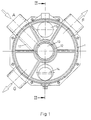
- the rotary slide valve has seven connections A to G, of which the connections A, F and G are arranged radially on the circumference of the cylindrical rotary valve housing and the connections B, C on the side surface facing the pump and the connections D and E on the side surface facing away from the pump of the rotary valve.
- the Cylinder end faces perpendicular to the cylinder axis the surface 2 being used for flange mounting directly on the side surface of a pump 4 or a disc-shaped coarse filter 5 connected in between.
- the side surface of a filter kettle 6 is attached.
- the inlets and outlets B to E arranged in the areas 2, 3 are aligned with the outlets and inlets of the connected devices 4 or 5 and 6.
- valve actuator 7 In the cylindrical housing 1 there is a coaxial, in particular disk-shaped rotary valve as valve actuator 7, which connects the channels in the housing to one another in different ways with chambers and lines or openings, depending on the respective rotational position of the actuator 7.
- the actuator has on its outer circumference a toothed ring 8, in which a bevel gear 9 engages, the axis of which is arranged radially and which is connected via a shaft 10 to a rotary knob 11 or a servomotor which projects on the outside of the housing 1 and can be operated by hand .
- the transmission ratio between the ring 8 and the bevel gear 9 is 6: 1, so that with a full rotation of the handwheel 11 the actuator 7 rotates by 60 degrees and thus changes from one connection position to another connection position.
- the actuator 7 has a central coaxial cylindrical opening 7a with which it is mounted on a cylindrical hollow connector 12 which is arranged in the housing 1, in particular is molded onto the housing.
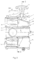
- the opening 7a or the nozzle 12 thus form a coaxial channel 13 which opens in the center of the surface 2 and forms the connection opening B there.
- channel 13 is over a radial line 17 connected to the terminal A.
- the channel 13 can also be carried out as far as surface 3, so that it then forms a further connection opening in surface 3.
- connection A is continuously connected to the connection B via the radial line and the channel 13, without being able to be closed by the actuator 7. Furthermore, there is a laterally offset connection opening C in the surface 2, which is connected to the connection opening D in the surface 3 via an axis-parallel channel 14 depending on the position of the actuator 7. Diametrically opposite, the surface 3 also has the connection opening E, which leads to the actuator 7 via an axially parallel channel and from which it can be connected to the connection F via a chamber 16.
- connection opening E which leads to the actuator 7 via an axially parallel channel and from which it can be connected to the connection F via a chamber 16.
- the rotary slide valve is attached with its disk-shaped housing 1 between the filter vessel 6 and the coarse filter 5, the pump 4 being attached on the other side of the disk-shaped filter 5.
- the filter 5 can be omitted, so that the housing 1 can also be attached directly to the pump 4.
- the connections are connected as follows:
- the connections are connected to one another by the actuator 7 in such a way that the water in the swimming pool is sucked off, filtered and then pumped back into the swimming pool.
- the pump 4 sucks in the water via the connection A, which flows via the radial channel to the channel 13 and via the connection B and the coarse filter 5 to the inlet 4a of the pump. From there, the water passes via the outlet 4b of the pump and the channel 5a to the connection C and via the channel 14 to the connection D. It then flows through the filter vessel 6 to the connection E and via channel 15 and chamber 16 to the connection F and from there back to the pool.
- the water flows from the connection A via the filter 5 and pump 4 to the connection C and from there via the actuator 7 to the connection E, so that the filter vessel 6 flows through in the opposite direction. From the connection D the water then flows together with the dirt particles of the boiler 6 to the connection G and thus to the waste water or the sewage system.
- connection A to connection B and from there via filter 5 and pump 4 to connection C and from this via connection D, filter vessel 6, Port E, chamber 16 and port G to waste water.
- the pool water If the pool water is only to be pumped around, without flowing through the filter vessel 6, it flows in the further rotary position of the actuator 7 from the connection A via the connection B, the filter 5, the pump 4, the connection C and the actuator 7 to the connection F.
- connection A In connection A to connection B and through filter 5, pump 4 and connection C via actuator 7 to connection G and thus to the channel.
Landscapes
- Engineering & Computer Science (AREA)
- General Engineering & Computer Science (AREA)
- Mechanical Engineering (AREA)
- Multiple-Way Valves (AREA)
- Sliding Valves (AREA)
- Valve-Gear Or Valve Arrangements (AREA)
- Details Of Reciprocating Pumps (AREA)
- Drilling Tools (AREA)
- Check Valves (AREA)
- Lift Valve (AREA)
Claims (7)
- Tiroir rotatif avec un organe de réglage (7) de vanne en forme de disque circulaire monté dans le carter (1) du tiroir, qui est réglable en rotation autour de l'axe du tiroir et présente des ouvertures et/ou des évidements par lesquels des ouvertures d'entrée et de sortie (A-G) du carter (1) du tiroir peuvent être reliées les unes aux autres au choix, un canal (13) étant disposé dans le carter (1) du tiroir coaxialement à l'axe du tiroir, traversant l'organe de réglage (7) et débouchant (ouverture d'embouchure B) dans une première face latérale plane extérieure (2) du carter (1) qui se trouve orthogonale au canal (13),
caractérisé en ce qu'une seconde face extérieure (3), dirigée parallèlement à la première face extérieure est formée sur le carter du tiroir, sur sa face opposée à la première face latérale plane extérieure (2), qui présente deux des ouvertures d'entrée ou de sortie (D-E) et sur laquelle peut être fixé un dispositif. - Tiroir rotatif selon la revendication 1,
caractérisé en ce que les ouvertures d'entrée et de sortie (A-G) sont réalisées sous forme de chambres (16) qui sont reliées respectivement à des conduites de raccordement (14, 15). - Tiroir rotatif selon la revendication 1 ou 2,
caractérisé en ce que le canal (13) débouche aussi dans la seconde face latérale extérieure (3). - Tiroir rotatif selon l'une des revendications 1 à 3,
caractérisé en ce que des dispositifs, en particulier une pompe (14) ou un carter de filtre (5), peuvent être fixés par leur face latérale également extérieure aux deux faces latérales planes extérieures (2, 3) du carter (1), cette face extérieure présentant respectivement une ouverture de passage qui est alignée avec l'ouverture d'embouchure (B) du canal (13) dans la face latérale (2) du tiroir rotatif. - Tiroir rotatif selon l'une des revendications précédentes,
caractérisé en ce que l'extrémité du canal (13) opposée à l'ouverture d'embouchure (B) est fermée en particulier en direction axiale et est reliée à un second canal radial (17) qui conduit à un tuyau de raccordement (A). - Tiroir rotatif selon l'une des revendications précédentes,
caractérisé en ce que l'organe de réglage (7) de vanne porte sur le bord extérieur une couronne dentée (8) dans laquelle vient en prise un pignon ou une roue conique (9) de déplacement, qui est relié à un entraînement par l'intermédiaire d'un arbre (10). - Tiroir rotatif selon la revendication 6,
caractérisé en ce que l'entraînement à couronne dentée (8, 9) présente un rapport de réduction de 6:1.
Priority Applications (1)
| Application Number | Priority Date | Filing Date | Title |
|---|---|---|---|
| AT90113506T ATE103376T1 (de) | 1989-07-31 | 1990-07-14 | Drehschieber. |
Applications Claiming Priority (2)
| Application Number | Priority Date | Filing Date | Title |
|---|---|---|---|
| DE3925270 | 1989-07-31 | ||
| DE3925270A DE3925270A1 (de) | 1989-07-31 | 1989-07-31 | Drehschieber |
Publications (3)
| Publication Number | Publication Date |
|---|---|
| EP0411368A2 EP0411368A2 (fr) | 1991-02-06 |
| EP0411368A3 EP0411368A3 (en) | 1991-07-03 |
| EP0411368B1 true EP0411368B1 (fr) | 1994-03-23 |
Family
ID=6386195
Family Applications (1)
| Application Number | Title | Priority Date | Filing Date |
|---|---|---|---|
| EP90113506A Expired - Lifetime EP0411368B1 (fr) | 1989-07-31 | 1990-07-14 | Tiroir rotatif |
Country Status (4)
| Country | Link |
|---|---|
| EP (1) | EP0411368B1 (fr) |
| AT (1) | ATE103376T1 (fr) |
| DE (2) | DE3925270A1 (fr) |
| ES (1) | ES2050891T3 (fr) |
Families Citing this family (4)
| Publication number | Priority date | Publication date | Assignee | Title |
|---|---|---|---|---|
| US6186174B1 (en) | 1997-10-01 | 2001-02-13 | Muskin Leisure Products, Inc. | Valve assembly |
| RU2175735C1 (ru) * | 2001-01-25 | 2001-11-10 | Немытко Виктор Ефимович | Кран |
| DE10336165A1 (de) * | 2003-08-07 | 2005-02-24 | Alstom Technology Ltd | Schalteinrichtung |
| AU2011311175B2 (en) * | 2010-10-07 | 2016-06-30 | Amiad Water Systems Ltd. | Fluid filtering unit and system |
Family Cites Families (6)
| Publication number | Priority date | Publication date | Assignee | Title |
|---|---|---|---|---|
| US2062994A (en) * | 1932-08-06 | 1936-12-01 | Julius C Vredenburg | Apparatus for aerating liquids |
| US3365064A (en) * | 1965-10-14 | 1968-01-23 | Jacuzzi Bros Inc | Swimming pool system and backwash assembly therefor |
| US3520327A (en) * | 1968-05-28 | 1970-07-14 | Ross Operating Valve Co | Station selector valve |
| US4216798A (en) * | 1977-01-26 | 1980-08-12 | Coleco Industries, Inc. | Rotary valve |
| DE3436079A1 (de) * | 1984-10-02 | 1986-04-10 | Leybold-Heraeus GmbH, 5000 Köln | Oelgedichtete vakuumpumpe |
| DE3545681A1 (de) * | 1985-12-21 | 1987-07-02 | Gerhard Gramm | Vorrichtung zum wahlweisen verbinden von leitungen fuer fliessfaehige medien |
-
1989
- 1989-07-31 DE DE3925270A patent/DE3925270A1/de active Granted
-
1990
- 1990-07-14 DE DE90113506T patent/DE59005070D1/de not_active Expired - Fee Related
- 1990-07-14 AT AT90113506T patent/ATE103376T1/de not_active IP Right Cessation
- 1990-07-14 EP EP90113506A patent/EP0411368B1/fr not_active Expired - Lifetime
- 1990-07-14 ES ES90113506T patent/ES2050891T3/es not_active Expired - Lifetime
Also Published As
| Publication number | Publication date |
|---|---|
| EP0411368A3 (en) | 1991-07-03 |
| DE3925270C2 (fr) | 1993-08-05 |
| DE3925270A1 (de) | 1991-02-14 |
| DE59005070D1 (de) | 1994-04-28 |
| ATE103376T1 (de) | 1994-04-15 |
| ES2050891T3 (es) | 1994-06-01 |
| EP0411368A2 (fr) | 1991-02-06 |
Similar Documents
| Publication | Publication Date | Title |
|---|---|---|
| DE69009334T2 (de) | Aquariumpumpe mit umkehrbarer und einstellbarer Strömung. | |
| DE69116632T2 (de) | Vierteldrehungshahn | |
| DE1550060B2 (de) | Mischventil mit gekapselten steuerungsteilen | |
| DE102007019064B3 (de) | Drehschieber | |
| DE2413420A1 (de) | Mischbatteriesystem | |
| EP0166160A1 (fr) | Filtre pour carburant Diésel | |
| DE4228565A1 (de) | Ventil mit Voreinstellung | |
| EP0411368B1 (fr) | Tiroir rotatif | |
| EP0401633B1 (fr) | Armature de filtre lavable à contre-courant | |
| EP0246359B1 (fr) | Vanne thermostatique pour le réfrigérant d'un moteur à combustion interne | |
| EP0501953B1 (fr) | Melangeur sanitaire | |
| CH653266A5 (en) | Self-cleaning filter for water supply systems | |
| DE3030447A1 (de) | Mehrwegehahn, insbesondere dreiwegehahn | |
| EP0253388B1 (fr) | Dispositif de réglage de conduites d'arrosage de champs | |
| DE10061441A1 (de) | Ventil, insbesondere Heizkörperventil | |
| CH675458A5 (fr) | ||
| DE102022112249B4 (de) | Wassersparende, durch Drücken zu betätigende Schaltstruktur für den Wasserdurchfluss | |
| EP1821012A2 (fr) | Soupape à plusieurs voies | |
| DE202004002938U1 (de) | Mehrwegearmatur | |
| EP1055826B1 (fr) | Soupape avec piéce de fermeture remplaçable | |
| DE2638998C3 (de) | Dosiervorrichtung zur mengeneinstellbaren Zugabe von zwei oder mehreren Flüssigkeitskomponenten | |
| EP4375431A1 (fr) | Bassin avec bouche d'écoulement | |
| WO2006056147A1 (fr) | Accessoire de canalisation multivoie | |
| DE202023102797U1 (de) | Rückspülfilteranordnung | |
| DE2432629A1 (de) | Steuerventil fuer vakuum-tanks od. dgl. |
Legal Events
| Date | Code | Title | Description |
|---|---|---|---|
| PUAI | Public reference made under article 153(3) epc to a published international application that has entered the european phase |
Free format text: ORIGINAL CODE: 0009012 |
|
| AK | Designated contracting states |
Kind code of ref document: A2 Designated state(s): AT BE CH DE DK ES FR GB GR IT LI LU NL SE |
|
| PUAL | Search report despatched |
Free format text: ORIGINAL CODE: 0009013 |
|
| AK | Designated contracting states |
Kind code of ref document: A3 Designated state(s): AT BE CH DE DK ES FR GB GR IT LI LU NL SE |
|
| 17P | Request for examination filed |
Effective date: 19910606 |
|
| RAP1 | Party data changed (applicant data changed or rights of an application transferred) |
Owner name: WILO GMBH |
|
| 17Q | First examination report despatched |
Effective date: 19921110 |
|
| GRAA | (expected) grant |
Free format text: ORIGINAL CODE: 0009210 |
|
| AK | Designated contracting states |
Kind code of ref document: B1 Designated state(s): AT BE CH DE DK ES FR GB GR IT LI LU NL SE |
|
| PG25 | Lapsed in a contracting state [announced via postgrant information from national office to epo] |
Ref country code: SE Free format text: THE PATENT HAS BEEN ANNULLED BY A DECISION OF A NATIONAL AUTHORITY Effective date: 19940323 Ref country code: NL Effective date: 19940323 Ref country code: GR Free format text: LAPSE BECAUSE OF FAILURE TO SUBMIT A TRANSLATION OF THE DESCRIPTION OR TO PAY THE FEE WITHIN THE PRESCRIBED TIME-LIMIT Effective date: 19940323 Ref country code: GB Effective date: 19940323 Ref country code: DK Effective date: 19940323 Ref country code: BE Effective date: 19940323 |
|
| REF | Corresponds to: |
Ref document number: 103376 Country of ref document: AT Date of ref document: 19940415 Kind code of ref document: T |
|
| ET | Fr: translation filed | ||
| REF | Corresponds to: |
Ref document number: 59005070 Country of ref document: DE Date of ref document: 19940428 |
|
| REG | Reference to a national code |
Ref country code: ES Ref legal event code: FG2A Ref document number: 2050891 Country of ref document: ES Kind code of ref document: T3 |
|
| ITF | It: translation for a ep patent filed | ||
| PG25 | Lapsed in a contracting state [announced via postgrant information from national office to epo] |
Ref country code: AT Effective date: 19940714 |
|
| PG25 | Lapsed in a contracting state [announced via postgrant information from national office to epo] |
Ref country code: LU Free format text: LAPSE BECAUSE OF NON-PAYMENT OF DUE FEES Effective date: 19940731 Ref country code: LI Effective date: 19940731 Ref country code: CH Effective date: 19940731 |
|
| NLV1 | Nl: lapsed or annulled due to failure to fulfill the requirements of art. 29p and 29m of the patents act | ||
| GBV | Gb: ep patent (uk) treated as always having been void in accordance with gb section 77(7)/1977 [no translation filed] |
Effective date: 19940323 |
|
| PLBE | No opposition filed within time limit |
Free format text: ORIGINAL CODE: 0009261 |
|
| STAA | Information on the status of an ep patent application or granted ep patent |
Free format text: STATUS: NO OPPOSITION FILED WITHIN TIME LIMIT |
|
| 26N | No opposition filed | ||
| REG | Reference to a national code |
Ref country code: CH Ref legal event code: PL |
|
| PGFP | Annual fee paid to national office [announced via postgrant information from national office to epo] |
Ref country code: ES Payment date: 19950725 Year of fee payment: 6 |
|
| PG25 | Lapsed in a contracting state [announced via postgrant information from national office to epo] |
Ref country code: ES Free format text: LAPSE BECAUSE OF EXPIRATION OF PROTECTION Effective date: 19960715 |
|
| REG | Reference to a national code |
Ref country code: ES Ref legal event code: FD2A Effective date: 19990601 |
|
| PGFP | Annual fee paid to national office [announced via postgrant information from national office to epo] |
Ref country code: FR Payment date: 20010626 Year of fee payment: 12 |
|
| PGFP | Annual fee paid to national office [announced via postgrant information from national office to epo] |
Ref country code: DE Payment date: 20010824 Year of fee payment: 12 |
|
| PG25 | Lapsed in a contracting state [announced via postgrant information from national office to epo] |
Ref country code: DE Free format text: LAPSE BECAUSE OF NON-PAYMENT OF DUE FEES Effective date: 20030201 |
|
| PG25 | Lapsed in a contracting state [announced via postgrant information from national office to epo] |
Ref country code: FR Free format text: LAPSE BECAUSE OF NON-PAYMENT OF DUE FEES Effective date: 20030331 |
|
| REG | Reference to a national code |
Ref country code: FR Ref legal event code: ST |
|
| PG25 | Lapsed in a contracting state [announced via postgrant information from national office to epo] |
Ref country code: IT Free format text: LAPSE BECAUSE OF NON-PAYMENT OF DUE FEES;WARNING: LAPSES OF ITALIAN PATENTS WITH EFFECTIVE DATE BEFORE 2007 MAY HAVE OCCURRED AT ANY TIME BEFORE 2007. THE CORRECT EFFECTIVE DATE MAY BE DIFFERENT FROM THE ONE RECORDED. Effective date: 20050714 |