EP0411368B1 - Rotary disk valve - Google Patents
Rotary disk valve Download PDFInfo
- Publication number
- EP0411368B1 EP0411368B1 EP90113506A EP90113506A EP0411368B1 EP 0411368 B1 EP0411368 B1 EP 0411368B1 EP 90113506 A EP90113506 A EP 90113506A EP 90113506 A EP90113506 A EP 90113506A EP 0411368 B1 EP0411368 B1 EP 0411368B1
- Authority
- EP
- European Patent Office
- Prior art keywords
- disc valve
- channel
- rotary disc
- lateral face
- casing
- Prior art date
- Legal status (The legal status is an assumption and is not a legal conclusion. Google has not performed a legal analysis and makes no representation as to the accuracy of the status listed.)
- Expired - Lifetime
Links
- 230000005540 biological transmission Effects 0.000 claims description 2
- XLYOFNOQVPJJNP-UHFFFAOYSA-N water Substances O XLYOFNOQVPJJNP-UHFFFAOYSA-N 0.000 description 12
- 230000009182 swimming Effects 0.000 description 5
- 238000004140 cleaning Methods 0.000 description 3
- 238000001914 filtration Methods 0.000 description 3
- 239000010865 sewage Substances 0.000 description 3
- 238000011001 backwashing Methods 0.000 description 2
- 238000005086 pumping Methods 0.000 description 2
- 239000002351 wastewater Substances 0.000 description 2
- 241001136792 Alle Species 0.000 description 1
- 238000010276 construction Methods 0.000 description 1
- 238000004519 manufacturing process Methods 0.000 description 1
- 238000000034 method Methods 0.000 description 1
- 239000002245 particle Substances 0.000 description 1
Images

Classifications
-
- F—MECHANICAL ENGINEERING; LIGHTING; HEATING; WEAPONS; BLASTING
- F16—ENGINEERING ELEMENTS AND UNITS; GENERAL MEASURES FOR PRODUCING AND MAINTAINING EFFECTIVE FUNCTIONING OF MACHINES OR INSTALLATIONS; THERMAL INSULATION IN GENERAL
- F16K—VALVES; TAPS; COCKS; ACTUATING-FLOATS; DEVICES FOR VENTING OR AERATING
- F16K11/00—Multiple-way valves, e.g. mixing valves; Pipe fittings incorporating such valves
- F16K11/02—Multiple-way valves, e.g. mixing valves; Pipe fittings incorporating such valves with all movable sealing faces moving as one unit
- F16K11/06—Multiple-way valves, e.g. mixing valves; Pipe fittings incorporating such valves with all movable sealing faces moving as one unit comprising only sliding valves, i.e. sliding closure elements
- F16K11/072—Multiple-way valves, e.g. mixing valves; Pipe fittings incorporating such valves with all movable sealing faces moving as one unit comprising only sliding valves, i.e. sliding closure elements with pivoted closure members
- F16K11/074—Multiple-way valves, e.g. mixing valves; Pipe fittings incorporating such valves with all movable sealing faces moving as one unit comprising only sliding valves, i.e. sliding closure elements with pivoted closure members with flat sealing faces
Definitions
- the invention relates to a rotary slide valve with a circular disc-shaped valve actuator mounted in the slide housing, which is rotatably adjustable about the slide axis and has openings and / or recesses via which the inlet and outlet openings of the slide valve housing can optionally be connected to one another, with a channel coaxial to the slide axis in the slide housing is arranged, which penetrates the actuator and opens into a first outer flat side surface of the housing, which is perpendicular to the channel.
- Rotary valves are known and are used in many different ways. In practice, additional lines are installed for the connection between the rotary valve and the pump as well as for connection to other parts, in particular to a filter. This is labor and space consuming.
- the object of the invention is to improve a rotary slide valve of the type mentioned in such a way that simple construction and manufacture require little assembly effort and, in particular in the assembled state, the outer dimensions are small.
- a second outer side surface parallel to the first side surface is formed, which has two of the inflow or outflow openings and to which a device can be fastened .
- Such a rotary slide valve can be mounted directly between two side walls on devices such as pumps and / or filters, the flows of which are to be controlled by the rotary slide valve, without additional intermediate lines to be installed. This not only makes assembly much easier, but also a particularly space-saving design is achieved, since the rotary valve can be installed as a sandwich component between these devices. This also increases security against leaks, since instead of two connection points at the two ends of each line there is only one connection point per line.
- the coaxial channel arranged in the slide housing can be connected directly to the inlet of a pump, which is arranged coaxially in a side face of a pump, so that the side faces of the pump and rotary slide valve lie directly against one another.
- the opposite free parallel Side surface of this rotary valve is used to attach a second device including connections.
- at least two connections are provided in each of the two opposite, parallel side surfaces of the rotary slide valve, which are aligned with corresponding connections of the connected devices.
- the two side surfaces of the rotary valve are used for connections and seals.
- the coaxial channel can open into the second side surface.
- devices in particular a pump or a filter housing
- their outer side surface which side surface has a flow opening in each case which is in line with the opening of the channel in the outer side surface of the rotary slide valve flees.
- the end of the coaxial channel, which faces away from the outer flat side surface is closed in an axial direction in particular and is connected to a radial, second channel which leads to a connecting piece.
- valve actuator carries a ring gear on the outer edge, into which a pinion or bevel gear engages for adjustment, which is connected via a shaft to a drive, in particular a handwheel.
- ring gear drive can have a gear ratio of 6: 1. This translation ensures that with each turn of the rotary handle or the actuator, the valve actuator rotates by 60 degrees, so that the connecting channels and connecting chamber in the rotary valve can be arranged at a 60-degree distance, thus preventing incorrect operation with high security .
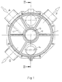
- the rotary slide valve has seven connections A to G, of which the connections A, F and G are arranged radially on the circumference of the cylindrical rotary valve housing and the connections B, C on the side surface facing the pump and the connections D and E on the side surface facing away from the pump of the rotary valve.
- the Cylinder end faces perpendicular to the cylinder axis the surface 2 being used for flange mounting directly on the side surface of a pump 4 or a disc-shaped coarse filter 5 connected in between.
- the side surface of a filter kettle 6 is attached.
- the inlets and outlets B to E arranged in the areas 2, 3 are aligned with the outlets and inlets of the connected devices 4 or 5 and 6.
- valve actuator 7 In the cylindrical housing 1 there is a coaxial, in particular disk-shaped rotary valve as valve actuator 7, which connects the channels in the housing to one another in different ways with chambers and lines or openings, depending on the respective rotational position of the actuator 7.
- the actuator has on its outer circumference a toothed ring 8, in which a bevel gear 9 engages, the axis of which is arranged radially and which is connected via a shaft 10 to a rotary knob 11 or a servomotor which projects on the outside of the housing 1 and can be operated by hand .
- the transmission ratio between the ring 8 and the bevel gear 9 is 6: 1, so that with a full rotation of the handwheel 11 the actuator 7 rotates by 60 degrees and thus changes from one connection position to another connection position.
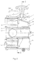
- the actuator 7 has a central coaxial cylindrical opening 7a with which it is mounted on a cylindrical hollow connector 12 which is arranged in the housing 1, in particular is molded onto the housing.
- the opening 7a or the nozzle 12 thus form a coaxial channel 13 which opens in the center of the surface 2 and forms the connection opening B there.
- channel 13 is over a radial line 17 connected to the terminal A.
- the channel 13 can also be carried out as far as surface 3, so that it then forms a further connection opening in surface 3.
- connection A is continuously connected to the connection B via the radial line and the channel 13, without being able to be closed by the actuator 7. Furthermore, there is a laterally offset connection opening C in the surface 2, which is connected to the connection opening D in the surface 3 via an axis-parallel channel 14 depending on the position of the actuator 7. Diametrically opposite, the surface 3 also has the connection opening E, which leads to the actuator 7 via an axially parallel channel and from which it can be connected to the connection F via a chamber 16.
- connection opening E which leads to the actuator 7 via an axially parallel channel and from which it can be connected to the connection F via a chamber 16.
- the rotary slide valve is attached with its disk-shaped housing 1 between the filter vessel 6 and the coarse filter 5, the pump 4 being attached on the other side of the disk-shaped filter 5.
- the filter 5 can be omitted, so that the housing 1 can also be attached directly to the pump 4.
- the connections are connected as follows:
- the connections are connected to one another by the actuator 7 in such a way that the water in the swimming pool is sucked off, filtered and then pumped back into the swimming pool.
- the pump 4 sucks in the water via the connection A, which flows via the radial channel to the channel 13 and via the connection B and the coarse filter 5 to the inlet 4a of the pump. From there, the water passes via the outlet 4b of the pump and the channel 5a to the connection C and via the channel 14 to the connection D. It then flows through the filter vessel 6 to the connection E and via channel 15 and chamber 16 to the connection F and from there back to the pool.
- the water flows from the connection A via the filter 5 and pump 4 to the connection C and from there via the actuator 7 to the connection E, so that the filter vessel 6 flows through in the opposite direction. From the connection D the water then flows together with the dirt particles of the boiler 6 to the connection G and thus to the waste water or the sewage system.
- connection A to connection B and from there via filter 5 and pump 4 to connection C and from this via connection D, filter vessel 6, Port E, chamber 16 and port G to waste water.
- the pool water If the pool water is only to be pumped around, without flowing through the filter vessel 6, it flows in the further rotary position of the actuator 7 from the connection A via the connection B, the filter 5, the pump 4, the connection C and the actuator 7 to the connection F.
- connection A In connection A to connection B and through filter 5, pump 4 and connection C via actuator 7 to connection G and thus to the channel.
Landscapes
- Engineering & Computer Science (AREA)
- General Engineering & Computer Science (AREA)
- Mechanical Engineering (AREA)
- Multiple-Way Valves (AREA)
- Sliding Valves (AREA)
- Valve-Gear Or Valve Arrangements (AREA)
- Details Of Reciprocating Pumps (AREA)
- Drilling Tools (AREA)
- Check Valves (AREA)
- Lift Valve (AREA)
Abstract
Description
Die Erfindung betrifft einen Drehschieber mit einem kreisscheibenförmigen, im Schiebergehäuse gelagerten Ventilstellglied, das um die Schieberachse drehverstellbar ist und Öffnungen und/oder Ausnehmungen aufweist, über die Zufluß- und Abflußöffnungen des Schiebergehäuses wahlweise miteinander verbunden werden können, wobei im Schiebergehäuse ein Kanal koaxial zur Schieberachse angeordnet ist, der das Stellglied durchdringt und in einer ersten äußeren ebenen Seitenfläche des Gehäuses mündet, die rechtwinklig zum Kanal liegt.The invention relates to a rotary slide valve with a circular disc-shaped valve actuator mounted in the slide housing, which is rotatably adjustable about the slide axis and has openings and / or recesses via which the inlet and outlet openings of the slide valve housing can optionally be connected to one another, with a channel coaxial to the slide axis in the slide housing is arranged, which penetrates the actuator and opens into a first outer flat side surface of the housing, which is perpendicular to the channel.
Drehschieber sind bekannt und werden vielfältig eingesetzt. In der Praxis werden für die Verbindung sowohl zwischen Drehschieber und Pumpe als auch zum Anschluß an andere Teile, insbesondere an einen Filter, zusätzliche Leitungen montiert. Dies ist arbeits- und platzaufwendig.Rotary valves are known and are used in many different ways. In practice, additional lines are installed for the connection between the rotary valve and the pump as well as for connection to other parts, in particular to a filter. This is labor and space consuming.
Aus der US-A-4 216 798 ist ein Drehschieber der eingangs genannten Art an einem Filterbehälter bekannt. Dieser bekannte Drehschieber hat große Außenabmessungen und ist an unterschiedlichen Vorrichtungen nicht einsetzbar.From US-A-4 216 798 a rotary valve of the type mentioned on a filter container is known. This known rotary valve has large external dimensions and cannot be used on different devices.
Aufgabe der Erfindung ist es, einen Drehschieber der eingangs genannten Art so zu verbessern, daß bei einfacher Konstruktion und Herstellung ein geringer Montageaufwand erforderlich ist und insbesondere im montierten Zustand die Außenabmessungen gering sind.The object of the invention is to improve a rotary slide valve of the type mentioned in such a way that simple construction and manufacture require little assembly effort and, in particular in the assembled state, the outer dimensions are small.
Diese Aufgabe wird erfindungsgemäß dadurch gelöst, daß an dem Schiebergehäuse, auf dessen der ersten äußeren ebenen Seitenfläche gegenüberliegenden Seite, eine zu der ersten Seitenfläche parallel gerichtete zweite äußere Seitenfläche ausgebildet ist, die zwei der Zufluß- oder Abflußöffnungen aufweist und an der eine Vorrichtung befestigbar ist.This object is achieved in that on the slide housing, on the side opposite the first outer flat side surface, a second outer side surface parallel to the first side surface is formed, which has two of the inflow or outflow openings and to which a device can be fastened .
Ein solcher Drehschieber läßt sich ohne zusätzlich zu montierende Zwischenleitungen direkt zwischen zwei Seitenwänden an Vorrichtungen wie Pumpe und/oder Filter montieren, deren Strömungen vom Drehschieber zu steuern sind. Damit wird nicht nur die Montage wesentlich einfacher, sondern es wird auch eine besonders platzsparende Bauweise erreicht, da der Drehschieber als Sandwichbauteil zwischen diese Vorrichtungen montiert werden kann. Hierdurch wird auch die Sicherheit gegen Undichtigkeiten erhöht, da statt zweier Verbindungsstellen an den beiden Enden jeder Leitung nur noch eine Verbindungsstelle pro Leitung vorhanden ist.Such a rotary slide valve can be mounted directly between two side walls on devices such as pumps and / or filters, the flows of which are to be controlled by the rotary slide valve, without additional intermediate lines to be installed. This not only makes assembly much easier, but also a particularly space-saving design is achieved, since the rotary valve can be installed as a sandwich component between these devices. This also increases security against leaks, since instead of two connection points at the two ends of each line there is only one connection point per line.
Der im Schiebergehäuse angeordnete koaxiale Kanal kann direkt mit dem Einlaß einer Pumpe verbunden werden, der in einer Seitenfläche einer Pumpe koaxial angeordnet ist, so daß die Seitenflächen von Pumpe und Drehschieber direkt aneinander liegen. Die gegenüberliegende freie parallele Seitenfläche dieses Drehschiebers dient zum Befestigen einer zweiten Vorrichtung einschließlich Anschlüsse. Damit sind in beiden einander gegenüberliegenden parallelen Seitenflächen des Drehschiebers mindestens je zwei Anschlüsse vorgesehen, die mit entsprechenden Anschlüssen der angeschlossenen Vorrichtungen fluchten. Die zwei Seitenflächen des Drehschiebers dienen somit den Anschlüssen und Abdichtungen. Hierbei kann der koaxiale Kanal in der zweiten Seitenfläche münden.The coaxial channel arranged in the slide housing can be connected directly to the inlet of a pump, which is arranged coaxially in a side face of a pump, so that the side faces of the pump and rotary slide valve lie directly against one another. The opposite free parallel Side surface of this rotary valve is used to attach a second device including connections. In this way, at least two connections are provided in each of the two opposite, parallel side surfaces of the rotary slide valve, which are aligned with corresponding connections of the connected devices. The two side surfaces of the rotary valve are used for connections and seals. The coaxial channel can open into the second side surface.
Besonders vorteilhaft ist es, wenn an den äußeren ebenen Seitenflächen des Gehäuses Vorrichtungen, insbesondere eine Pumpe oder ein Filtergehäuse, mit ihrer ebenso äußeren Seitenfläche befestigbar sind, wobei diese Seitenfläche jeweils eine Durchflußöffnung aufweist, die mit der Mündungsöffnung des Kanals in der äußeren Seitenfläche des Drehschiebers fluchtet. Von großem Vorteil ist es auch, wenn das Ende des koaxialen Kanals, das der äußeren ebenen Seitenfläche abgewandt ist, in insbesondere axialer Richtung verschlossen ist und mit einem radialen, zweiten Kanal verbunden ist, der zu einem Anschlußstutzen führt.It is particularly advantageous if devices, in particular a pump or a filter housing, can be fastened to the outer flat side surfaces of the housing with their outer side surface, which side surface has a flow opening in each case which is in line with the opening of the channel in the outer side surface of the rotary slide valve flees. It is also of great advantage if the end of the coaxial channel, which faces away from the outer flat side surface, is closed in an axial direction in particular and is connected to a radial, second channel which leads to a connecting piece.
Besonders vorteilhaft ist es, wenn das Ventilstellglied am äußeren Rand einen Zahnkranz trägt, in das ein Ritzel oder Kegelrad zur Verstellung eingreift, das über eine Welle mit einem Antrieb, insbesondere einem Handrad verbunden ist. Hierbei kann der Zahnkranzantrieb ein Übersetzungsverhältnis von 6:1 aufweisen. Durch diese Übersetzung wird erreicht, daß bei jeder Umdrehung des Drehgriffs oder des Stellmotors das Ventilstellglied sich um 60 Grad weiterdreht, so daß die Verbindungskanäle und Verbindungskammer im Drehschieber im 60-Grad-Abstand angeordnet sein können, und damit eine Fehlbedienung mit hoher Sicherheit verhindert wird.It is particularly advantageous if the valve actuator carries a ring gear on the outer edge, into which a pinion or bevel gear engages for adjustment, which is connected via a shaft to a drive, in particular a handwheel. Here, the ring gear drive can have a gear ratio of 6: 1. This translation ensures that with each turn of the rotary handle or the actuator, the valve actuator rotates by 60 degrees, so that the connecting channels and connecting chamber in the rotary valve can be arranged at a 60-degree distance, thus preventing incorrect operation with high security .
Ein Ausführungsbeispiel der Erfindung ist in den Zeichnungen dargestellt und wird im folgenden näher beschrieben. Es zeigen :
- Fig. 1
- einen Querschnitt durch den Drehschieber nach I-I in
Figur 2, - Fig. 2
- einen axialen Schnitt durch den Drehschieber nach II-II in
Figur 1 und - Fig. 3
- einen axialen Längsschnitt durch den Drehschieber mit angeschlossenem Filterkessel, Grobfilter und Pumpe.
- Fig. 1
- 3 shows a cross section through the rotary slide valve according to II in FIG. 2,
- Fig. 2
- an axial section through the rotary valve according to II-II in Figure 1 and
- Fig. 3
- an axial longitudinal section through the rotary valve with connected filter tank, coarse filter and pump.
Der Drehschieber ist ein 5-Wege-Ventil und für die verschiedensten Zwecke vielfältig einsetzbar. Im folgenden wird er im Einsatz bei einem Schwimmbecken beschrieben, dessen Wasser zum Filtern umgepumpt wird. Hierbei treten folgende Arbeitsweisen auf:
- 1. Filtern des Wassers
- 2. Rückspülen, d.h. Reinigen des Filters
- 3. Klarspülen, d.h. Reinigen des Ventils und der Leitungen
- 4. Bypass, d.h. Umpumpen des Schwimmbeckenwassers ohne Filtern
- 5. Entleeren, d.h. Abpumpen des Schwimmbeckenwassers zur Kanalisation
- 6. Geschlossen, d.h. alle Leitungen sind geschlossen.
- 1. Filter the water
- 2. Backwashing, ie cleaning the filter
- 3. Rinse off, ie cleaning the valve and the lines
- 4. Bypass, ie pumping over the pool water without filtering
- 5. Emptying, ie pumping off the pool water to the sewage system
- 6. Closed, ie all lines are closed.
Der Drehschieber weist sieben Anschlüsse A bis G auf, von denen die Anschlüsse A, F und G am Umfang des zylindrischen Drehschiebergehäuses radial angeordnet sind und die Anschlüsse B, C auf der der Pumpe zugewandten und die Anschlüsse D und E auf der der Pumpe abgewandten Seitenfläche des Drehschiebers liegen. Hierbei sind die Zylinderstirnflächen rechtwinklig zur Zylinderachse, wobei die Fläche 2 zum Anflanschen direkt an der Seitenfläche einer Pumpe 4 oder einem dazwischen geschalteten scheibenförmigen Grobfilter 5 dient. An der Fläche 3 ist die Seitenfläche eines Filterkessels 6 befestigt.The rotary slide valve has seven connections A to G, of which the connections A, F and G are arranged radially on the circumference of the cylindrical rotary valve housing and the connections B, C on the side surface facing the pump and the connections D and E on the side surface facing away from the pump of the rotary valve. Here are the Cylinder end faces perpendicular to the cylinder axis, the
Die in den Flächen 2, 3 angeordneten Ein- und Auslässe B bis E fluchten mit den Aus- und Einlässen der angeschlossenen Vorrichtungen 4 bzw. 5 und 6.The inlets and outlets B to E arranged in the
Im zylindrischen Gehäuse 1 liegt koaxial ein insbesondere scheibenförmiger Drehschieber als Ventilstellglied 7 ein, das mit Kammern und Leitungen bzw. Öffnungen die im Gehäuse befindlichen Kanäle in unterschiedlicher Weise miteinander verbindet, abhängig von der jeweiligen Drehstellung des Stellgliedes 7.In the
Das Stellglied weist an seinem Außenumfang einen Zahnkranz 8 auf, in den ein Kegelrad 9 eingreift, dessen Achse radial angeordnet ist und das über eine Welle 10 mit einem Drehknopf 11 oder einem Stellmotor verbunden ist, der außen am Gehäuse 1 vorsteht und von Hand bedienbar ist. Das Übersetzungsverhältnis zwischen Kranz 8 und Kegelrad 9 beträgt zu 6:1, so daß bei einer vollen Umdrehung des Handrades 11 das Stellglied 7 sich um 60 Grad verdreht und damit von einer Verbindungsstellung in eine andere Verbindungsstellung wechselt.The actuator has on its outer circumference a
Das Stellglied 7 weist eine mittige koaxiale zylindrische Öffnung 7a auf, mit der es auf einem zylindrischen hohlen Stutzen 12 gelagert ist, der im Gehäuse 1 angeordnet, insbesondere am Gehäuse angeformt ist. Die Öffnung 7a bzw. der Stutzen 12 bilden damit einen koaxialen Kanal 13, der mittig in der Fläche 2 mündet und dort die Anschlußöffnung B bildet. Am gegenüberliegenden Ende ist der Kanal 13 über eine radiale Leitung 17 mit dem Anschluß A verbunden. Alternativ kann aber auch der Kanal 13 weiter bis zur Fläche 3 durchgeführt sein, so daß er dann in der Fläche 3 eine weitere Anschlußöffnung bildet.The
Im Ausführungsbeispiel ist der Anschluß A über die radiale Leitung und den Kanal 13 mit dem Anschluß B ständig verbunden, ohne durch das Stellglied 7 verschließbar zu sein. Ferner befindet sich in der Fläche 2 noch eine seitlich versetzte Anschlußöffnung C, die über einen achsparallelen Kanal 14 je nach Stellung des Stellgliedes 7 mit der Anschlußöffnung D in der Fläche 3 verbunden ist. Diametral gegenüberliegend weist die Fläche 3 noch die Anschlußöffnung E auf, die über einen achsparallelen Kanal zum Stellglied 7 führt und von diesem über eine Kammer 16 mit dem Anschluß F verbindbar ist. Die weiteren Verbindungswege, die durch das Stellglied 7 zwischen den einzelnen Anschlüssen A bis G geschaffen werden, sind der folgenden Funktionsbeschreibung entnehmbar:In the exemplary embodiment, the connection A is continuously connected to the connection B via the radial line and the
Der Drehschieber ist mit seinem scheibenförmigen Gehäuse 1 zwischen dem Filterkessel 6 und dem Grobfilter 5 befestigt, wobei auf der anderen Seite des scheibenförmigen Filters 5 die Pumpe 4 befestigt ist. Hierbei kann der Filter 5 entfallen, so daß das Gehäuse 1 auch direkt an der Pumpe 4 befestigt sein kann. Hierbei sind die Anschlüsse wie folgt verbunden:The rotary slide valve is attached with its disk-shaped
Anschluß A mit dem Auslaß des Schwimmbeckens, Anschluß B mit dem Einlaß 4a der Pumpe 4 unter möglicherweise der Zwischenschaltung des Grobfilters 5, Anschluß C mit dem Auslaß 4b der Pumpe 4 unter möglicherweise einer Zwischenschaltung einer Verbindungsleitung 5a im Gehäuse des Grobfilters 5, Anschluß D mit dem Einlaß des Filterkessels 6, Anschluß E mit dem Auslaß des Filterkessels 6, Anschluß F mit dem Einlaß des Schwimmbeckens und Anschluß G mit dem Einlaß zur Kanalisation.Port A with the outlet of the swimming pool, port B with the
In der in den Figuren dargestellten ersten Drehstellung "Filtern" sind die Anschlüsse in der Weise durch das Stellglied 7 miteinander verbunden, daß das Wasser des Schwimmbeckens abgesaugt, gefiltert und danach wieder in das Schwimmbecken zurückgepumpt wird. Hierbei saugt die Pumpe 4 über den Anschluß A das Wasser an, das über den radialen Kanal zum Kanal 13 fließt und über den Anschluß B und den Grobfilter 5 zum Einlaß 4a der Pumpe. Von dort gelangt das Wasser über den Auslaß 4b der Pumpe und den Kanal 5a zum Anschluß C und über den Kanal 14 zum Anschluß D. Es fließt dann durch den Filterkessel 6 zum Anschluß E und über Kanal 15 und Kammer 16 zum Anschluß F und von dort zurück ins Schwimmbecken.In the first rotary position "filtering" shown in the figures, the connections are connected to one another by the
In der zweiten Drehstellung "Rückspülen" des Stellglieds 7 fließt das Wasser vom Anschluß A über Filter 5 und Pumpe 4 zum Anschluß C und von dort über das Stellglied 7 zum Anschluß E, so daß der Filterkessel 6 in umgekehrter Richtung durchflossen wird. Vom Anschluß D fließt dann das Wasser zusammen mit den Schmutzteilchen des Kessels 6 zum Anschluß G und damit zum Abwasser bzw. zur Kanalisation.In the second rotary position "backwashing" of the
In der dritten Drehstellung "Klarspülen" bzw. Reinigen des Ventils und der Leitungen als auch der Pumpe fließt das Wasser vom Anschluß A zum Anschluß B und von dort über Filter 5 und Pumpe 4 zum Anschluß C und von diesem über Anschluß D, Filterkessel 6, Anschluß E, Kammer 16 und Anschluß G zum Abwasser.In the third rotary position "rinse-off" or cleaning of the valve and the lines as well as the pump, the water flows from connection A to connection B and from there via
Vierte Drehstellung "Bypass":Fourth rotary position "bypass":
Soll das Wasser des Schwimmbeckens nur umgepumpt werden, ohne durch den Filterkessel 6 zu strömen, so fließt es in der weiteren Drehstellung des Stellglieds 7 vom Anschluß A über den Anschluß B den Filter 5, die Pumpe 4, den Anschluß C und das Stellglied 7 zum Anschluß F.If the pool water is only to be pumped around, without flowing through the
In der fünften Drehstellung "Entleeren" fließt das Wasser vom Anschluß A zum Anschluß B und über Filter 5, Pumpe 4 und Anschluß C über das Stellglied 7 zum Anschluß G und damit zum Kanal.In the fifth rotary position "emptying" the water flows from connection A to connection B and through
In der sechsten Drehstellung "Geschlossen" des Ventilstellglieds 7 wird eine Schaltstellung erreicht, die Durchströmungen in oben beschriebener Weise nicht ermöglicht. Es wird damit auch eine mögliche Rückströmung aus dem Abwasserkanal verhindert.In the sixth rotational position "closed" of the
Claims (7)
- A rotary disc valve having a circular-disc-shaped valve adjustment member (7) which is mounted in the disc valve casing (1) and can be rotatably adjusted around the disc valve axis and is formed with apertures and/or recesses via which supply and discharge apertures (A-G) of the disc valve casing (1) can be optionally connected to one another, while disposed in the disc valve casing (1) coaxially with its axis is a channel (13) which extends through the adjusting member (7) and discharges in a first outer flat lateral face (2) of the casing (1) (discharge aperture B) which lies at right angles to the channel (13), characterized in that on its side opposite the first outer flat lateral face (2) the disc valve casing (1) is formed with a second outer lateral face (3) which is directed parallel with the first lateral face and which has two of the supply or discharge apertures (D, E) and to which a device can be attached.
- A rotary disc valve according to claim 1, characterized in that the supply and discharge apertures (A-G) are constructed in the form of chambers (16), each of which is connected to connecting lines (14, 15).
- A rotary disc valve according to claims 1 or 2, characterized in that the channel (13) also discharges in the second outer lateral face (3).
- A rotary disc valve according to one of claims 1 to 3, characterized in that devices, more particularly a pump (14) or a filter casing (5) can be attached via their outer lateral face to the outer flat lateral faces (2, 3) of the casing (1), the side face of each of said devices having a flow aperture which is aligned with the discharge aperture (B) of the channel (13) in the outer lateral face (2) of the rotary disc valve.
- A rotary disc valve according to one of the preceding claims, characterized in that the end of the channel (13) opposite the discharge aperture (B) is closed in more particularly the axial direction and connected to a radial second channel (17) which extends to a connecting spigot (A).
- A rotary disc valve according to one of the preceding claims, characterized in that the outer edge of the valve adjusting member (7) bears a toothed rim (8) in which a pinion or bevel wheel engages which is connected via a spindle (10) to a drive (9).
- A rotary disc valve according to claim 6, characterized in that the toothed rim drive (8, 9) has a transmission ratio of 6:1.
Priority Applications (1)
| Application Number | Priority Date | Filing Date | Title |
|---|---|---|---|
| AT90113506T ATE103376T1 (en) | 1989-07-31 | 1990-07-14 | ROTARY VALVE. |
Applications Claiming Priority (2)
| Application Number | Priority Date | Filing Date | Title |
|---|---|---|---|
| DE3925270 | 1989-07-31 | ||
| DE3925270A DE3925270A1 (en) | 1989-07-31 | 1989-07-31 | TURNTABLE |
Publications (3)
| Publication Number | Publication Date |
|---|---|
| EP0411368A2 EP0411368A2 (en) | 1991-02-06 |
| EP0411368A3 EP0411368A3 (en) | 1991-07-03 |
| EP0411368B1 true EP0411368B1 (en) | 1994-03-23 |
Family
ID=6386195
Family Applications (1)
| Application Number | Title | Priority Date | Filing Date |
|---|---|---|---|
| EP90113506A Expired - Lifetime EP0411368B1 (en) | 1989-07-31 | 1990-07-14 | Rotary disk valve |
Country Status (4)
| Country | Link |
|---|---|
| EP (1) | EP0411368B1 (en) |
| AT (1) | ATE103376T1 (en) |
| DE (2) | DE3925270A1 (en) |
| ES (1) | ES2050891T3 (en) |
Families Citing this family (4)
| Publication number | Priority date | Publication date | Assignee | Title |
|---|---|---|---|---|
| US6186174B1 (en) | 1997-10-01 | 2001-02-13 | Muskin Leisure Products, Inc. | Valve assembly |
| RU2175735C1 (en) * | 2001-01-25 | 2001-11-10 | Немытко Виктор Ефимович | Cock |
| DE10336165A1 (en) * | 2003-08-07 | 2005-02-24 | Alstom Technology Ltd | switching device |
| AU2011311175B2 (en) * | 2010-10-07 | 2016-06-30 | Amiad Water Systems Ltd. | Fluid filtering unit and system |
Family Cites Families (6)
| Publication number | Priority date | Publication date | Assignee | Title |
|---|---|---|---|---|
| US2062994A (en) * | 1932-08-06 | 1936-12-01 | Julius C Vredenburg | Apparatus for aerating liquids |
| US3365064A (en) * | 1965-10-14 | 1968-01-23 | Jacuzzi Bros Inc | Swimming pool system and backwash assembly therefor |
| US3520327A (en) * | 1968-05-28 | 1970-07-14 | Ross Operating Valve Co | Station selector valve |
| US4216798A (en) * | 1977-01-26 | 1980-08-12 | Coleco Industries, Inc. | Rotary valve |
| DE3436079A1 (en) * | 1984-10-02 | 1986-04-10 | Leybold-Heraeus GmbH, 5000 Köln | OIL-SEALED VACUUM PUMP |
| DE3545681A1 (en) * | 1985-12-21 | 1987-07-02 | Gerhard Gramm | Device for the selective connection of conduits for flowable media |
-
1989
- 1989-07-31 DE DE3925270A patent/DE3925270A1/en active Granted
-
1990
- 1990-07-14 DE DE90113506T patent/DE59005070D1/en not_active Expired - Fee Related
- 1990-07-14 AT AT90113506T patent/ATE103376T1/en not_active IP Right Cessation
- 1990-07-14 EP EP90113506A patent/EP0411368B1/en not_active Expired - Lifetime
- 1990-07-14 ES ES90113506T patent/ES2050891T3/en not_active Expired - Lifetime
Also Published As
| Publication number | Publication date |
|---|---|
| EP0411368A3 (en) | 1991-07-03 |
| DE3925270C2 (en) | 1993-08-05 |
| DE3925270A1 (en) | 1991-02-14 |
| DE59005070D1 (en) | 1994-04-28 |
| ATE103376T1 (en) | 1994-04-15 |
| ES2050891T3 (en) | 1994-06-01 |
| EP0411368A2 (en) | 1991-02-06 |
Similar Documents
| Publication | Publication Date | Title |
|---|---|---|
| DE69009334T2 (en) | Aquarium pump with reversible and adjustable flow. | |
| DE69116632T2 (en) | Quarter turn tap | |
| DE1550060B2 (en) | MIXING VALVE WITH ENCLOSED CONTROL PARTS | |
| DE102007019064B3 (en) | Rotary slide valve, particularly for coolant circuit, has device that is provided to couple cross section adjustment members to one another, which generates rotational angle difference between cross section adjustment members | |
| DE2413420A1 (en) | MIXING BATTERY SYSTEM | |
| EP0166160A1 (en) | Diesel fuel filter | |
| DE4228565A1 (en) | Valve with presetting | |
| EP0411368B1 (en) | Rotary disk valve | |
| EP0401633B1 (en) | Backwashable filter mounting | |
| EP0246359B1 (en) | Thermostatic valve for the coolant of an intrenal-combustion engine | |
| EP0501953B1 (en) | Tap-water mixer unit | |
| CH653266A5 (en) | Self-cleaning filter for water supply systems | |
| DE3030447A1 (en) | Fixed filter in multiway water tap - has soil removed by reversing flow direction | |
| EP0253388B1 (en) | Control device for field spraying conduits | |
| DE10061441A1 (en) | Valve, especially a radiator valve | |
| CH675458A5 (en) | ||
| DE102022112249B4 (en) | Water-saving, push-to-operate switching structure for water flow | |
| EP1821012A2 (en) | Multiway valve | |
| DE202004002938U1 (en) | 6-Way filter backwash valve for swimming pools has rotating annular valve body divided axially into distribution chambers with apertures cooperating with apertures in central chamber and outer casing | |
| EP1055826B1 (en) | Valve with replaceable closure element | |
| DE2638998C3 (en) | Dosing device for the quantity-adjustable addition of two or more liquid components | |
| EP4375431A1 (en) | Basin with drain | |
| WO2006056147A1 (en) | Multiport fitting | |
| DE202023102797U1 (en) | Backwash filter arrangement | |
| DE2432629A1 (en) | Multiple purpose control valve - used when sucking corrosive or contaminated fluids into tank and pumping it out has rotating valve body |
Legal Events
| Date | Code | Title | Description |
|---|---|---|---|
| PUAI | Public reference made under article 153(3) epc to a published international application that has entered the european phase |
Free format text: ORIGINAL CODE: 0009012 |
|
| AK | Designated contracting states |
Kind code of ref document: A2 Designated state(s): AT BE CH DE DK ES FR GB GR IT LI LU NL SE |
|
| PUAL | Search report despatched |
Free format text: ORIGINAL CODE: 0009013 |
|
| AK | Designated contracting states |
Kind code of ref document: A3 Designated state(s): AT BE CH DE DK ES FR GB GR IT LI LU NL SE |
|
| 17P | Request for examination filed |
Effective date: 19910606 |
|
| RAP1 | Party data changed (applicant data changed or rights of an application transferred) |
Owner name: WILO GMBH |
|
| 17Q | First examination report despatched |
Effective date: 19921110 |
|
| GRAA | (expected) grant |
Free format text: ORIGINAL CODE: 0009210 |
|
| AK | Designated contracting states |
Kind code of ref document: B1 Designated state(s): AT BE CH DE DK ES FR GB GR IT LI LU NL SE |
|
| PG25 | Lapsed in a contracting state [announced via postgrant information from national office to epo] |
Ref country code: SE Free format text: THE PATENT HAS BEEN ANNULLED BY A DECISION OF A NATIONAL AUTHORITY Effective date: 19940323 Ref country code: NL Effective date: 19940323 Ref country code: GR Free format text: LAPSE BECAUSE OF FAILURE TO SUBMIT A TRANSLATION OF THE DESCRIPTION OR TO PAY THE FEE WITHIN THE PRESCRIBED TIME-LIMIT Effective date: 19940323 Ref country code: GB Effective date: 19940323 Ref country code: DK Effective date: 19940323 Ref country code: BE Effective date: 19940323 |
|
| REF | Corresponds to: |
Ref document number: 103376 Country of ref document: AT Date of ref document: 19940415 Kind code of ref document: T |
|
| ET | Fr: translation filed | ||
| REF | Corresponds to: |
Ref document number: 59005070 Country of ref document: DE Date of ref document: 19940428 |
|
| REG | Reference to a national code |
Ref country code: ES Ref legal event code: FG2A Ref document number: 2050891 Country of ref document: ES Kind code of ref document: T3 |
|
| ITF | It: translation for a ep patent filed | ||
| PG25 | Lapsed in a contracting state [announced via postgrant information from national office to epo] |
Ref country code: AT Effective date: 19940714 |
|
| PG25 | Lapsed in a contracting state [announced via postgrant information from national office to epo] |
Ref country code: LU Free format text: LAPSE BECAUSE OF NON-PAYMENT OF DUE FEES Effective date: 19940731 Ref country code: LI Effective date: 19940731 Ref country code: CH Effective date: 19940731 |
|
| NLV1 | Nl: lapsed or annulled due to failure to fulfill the requirements of art. 29p and 29m of the patents act | ||
| GBV | Gb: ep patent (uk) treated as always having been void in accordance with gb section 77(7)/1977 [no translation filed] |
Effective date: 19940323 |
|
| PLBE | No opposition filed within time limit |
Free format text: ORIGINAL CODE: 0009261 |
|
| STAA | Information on the status of an ep patent application or granted ep patent |
Free format text: STATUS: NO OPPOSITION FILED WITHIN TIME LIMIT |
|
| 26N | No opposition filed | ||
| REG | Reference to a national code |
Ref country code: CH Ref legal event code: PL |
|
| PGFP | Annual fee paid to national office [announced via postgrant information from national office to epo] |
Ref country code: ES Payment date: 19950725 Year of fee payment: 6 |
|
| PG25 | Lapsed in a contracting state [announced via postgrant information from national office to epo] |
Ref country code: ES Free format text: LAPSE BECAUSE OF EXPIRATION OF PROTECTION Effective date: 19960715 |
|
| REG | Reference to a national code |
Ref country code: ES Ref legal event code: FD2A Effective date: 19990601 |
|
| PGFP | Annual fee paid to national office [announced via postgrant information from national office to epo] |
Ref country code: FR Payment date: 20010626 Year of fee payment: 12 |
|
| PGFP | Annual fee paid to national office [announced via postgrant information from national office to epo] |
Ref country code: DE Payment date: 20010824 Year of fee payment: 12 |
|
| PG25 | Lapsed in a contracting state [announced via postgrant information from national office to epo] |
Ref country code: DE Free format text: LAPSE BECAUSE OF NON-PAYMENT OF DUE FEES Effective date: 20030201 |
|
| PG25 | Lapsed in a contracting state [announced via postgrant information from national office to epo] |
Ref country code: FR Free format text: LAPSE BECAUSE OF NON-PAYMENT OF DUE FEES Effective date: 20030331 |
|
| REG | Reference to a national code |
Ref country code: FR Ref legal event code: ST |
|
| PG25 | Lapsed in a contracting state [announced via postgrant information from national office to epo] |
Ref country code: IT Free format text: LAPSE BECAUSE OF NON-PAYMENT OF DUE FEES;WARNING: LAPSES OF ITALIAN PATENTS WITH EFFECTIVE DATE BEFORE 2007 MAY HAVE OCCURRED AT ANY TIME BEFORE 2007. THE CORRECT EFFECTIVE DATE MAY BE DIFFERENT FROM THE ONE RECORDED. Effective date: 20050714 |