EP0410905A1 - Method for restarting and piecing of cored yarns made from fibres, new type of piecing realized by this method and spinning machine for carrying out this method - Google Patents
Method for restarting and piecing of cored yarns made from fibres, new type of piecing realized by this method and spinning machine for carrying out this method Download PDFInfo
- Publication number
- EP0410905A1 EP0410905A1 EP90420346A EP90420346A EP0410905A1 EP 0410905 A1 EP0410905 A1 EP 0410905A1 EP 90420346 A EP90420346 A EP 90420346A EP 90420346 A EP90420346 A EP 90420346A EP 0410905 A1 EP0410905 A1 EP 0410905A1
- Authority
- EP
- European Patent Office
- Prior art keywords
- fibers
- wire
- core
- condenser
- yarn
- Prior art date
- Legal status (The legal status is an assumption and is not a legal conclusion. Google has not performed a legal analysis and makes no representation as to the accuracy of the status listed.)
- Withdrawn
Links
Images


Classifications
-
- D—TEXTILES; PAPER
- D01—NATURAL OR MAN-MADE THREADS OR FIBRES; SPINNING
- D01H—SPINNING OR TWISTING
- D01H15/00—Piecing arrangements ; Automatic end-finding, e.g. by suction and reverse package rotation; Devices for temporarily storing yarn during piecing
Definitions
- the present invention relates to a process making it possible to produce and re-attach yarns of fibers comprising an internal core, yarns which in the following description will be designated by the expression "core yarns"; it also relates to a new type of piecing made using such a method as well as an improved spinning machine enabling it to be implemented.
- the most common is to introduce a multifilament core inside a wick, during the last spinning operation, that is to say on the continuous spinning, said core being introduced upstream of the last pair of wick stretching rollers.
- European patent no. 0206 956 (corresponding to patent US-A-4,757,680) describes an improvement made to such a technique and which in particular makes it possible to automate such machines and to perform in a simple, efficient and precise manner, the recovery operation after breakage of a wire or during any other intervention, or even when replacing a full spool with an empty winding support.
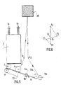
- spinning installations of the aforementioned type comprise, as illustrated in FIGS. 1, 2, 2a and 2b annexed (figures which are reproductions of FIGS. 6 to 9 of the aforementioned European patent no. 0206 956), a plurality of identical working positions arranged side by side on a support frame.
- Each working position essentially comprises, arranged between a source of fiber supply and a set for receiving the finished yarn (elements not shown in FIGS. 1 to 2b for simplification purposes), a treatment set proper, disposed at the outlet.
- a drawing system (designated by the general reference (E)), making it possible to treat two strands of fibers (1a, 1b), the fibers (1a) being intended to form the covering of the yarn while the fibers (1b ) are intended to form the soul.
- Such a spinning block consists essentially of a guide surface (4) or condenser element in the form of a hollow rotary cylinder pierced over its entire periphery with orifices (5). The rotary cylinder is subjected to the action of a suction source.
- a false twist pin (6) is arranged downstream of this condenser guide (4). Upstream of the condenser guide (4), is arranged a second condenser element (7) of a design similar to the condenser (4) and which is associated with a movable roller (8). Thanks to such an assembly, taking into account the twist communicated by the spindle (6) which rises to the nip between the condenser (7) and the roller (8), it is formed using fibers (10 ) from the wick (1b) a core (11).
- the fibers (9) which come from the wick (1a) and which are delivered to the surface of the condenser (4) are deposited against the surface of the core wire (11) and, taking account of the displacement of the latter and of the twisting which goes up, are blocked around this soul forming, in a way a covering.
- the core (7) and cover (4) condensing elements not only ensure the transfer of the fibers from the outlet of the drawing system (E), but also a parallelization of the fibers. elementary (9,10) as well as an additional stretching function of their peripheral speed.
- By adjusting the peripheral speeds of said condensers (4,7) it is possible to modify the composition of the yarn obtained (modification of the proportion of the fibers constituting the core (11) relative to the covering fibers) as well as the final titer.
- the covering condenser element (element 4) and the core condenser element (element 7), the false twist spindle (6) and the yarn calling system (13) ( 14) formed are grouped on a common box designated by the general reference (15) in Figure 2 in the form of a compact assembly. Furthermore, on this box, between the outlet of the stretching system (2,3) and the surface of the condenser (4,7), are arranged separating elements (16,17,18) forming guide channels allowing channel the elementary fibers (9,10) of the wicks (1a, 1b) well, avoiding not only fiber losses, but also any disturbance between the two fibrous flows.
- the recovery and reattachment method according to the invention during a spinning operation on a machine making it possible to produce a yarn of core fibers is characterized in that it comprises the succession of the following operations: - sampling of a length of yarn previously formed from the winding support; - setting aside a length of wire thus taken from inside a storage assembly; - Introduction in the form of a stretched strand of part of the yarn thus set aside inside all of the members allowing the making of the core yarn; - restarting of the winding and clutch assembly of the bodies of the processing blocks, the fibers coming from the drawing system (E) being put into waste; - during the advance of the starter thread on the spinning members: .
- a surface abrasion device allowing a refinement of the end of the launching wire is provided and is implemented when the fibrous flow intended to form the core is initiated.
- the method according to the invention can be implemented both when it is desired to make a connection following a breakage of the wire (either accidental or caused to eliminate a defect) during its production, and possibly when the we want to restart the machine by replacing a full coil with an empty support tube, in which case the latter will then include a few meters of wire previously formed and wound around it.
- the rotary roller (8) and one of the call cylinders of the output deliverer (13), in the present case the call cylinder (13a), are projecting with respect to the other elements of the spinning block (core condenser, cover condenser and false twist spindle); furthermore, the core and cover condensers have a conical front face.
- the storage assembly for the wire reserve is preferably in the form of a suction tube associated with a mobile element, sliding inside the tube, thus making it possible not only to bring the wire to the inside the work plan, but also facilitating the removal of the wire stored inside the reserve and its introduction into the different elements of the processing block.
- the method according to the invention consists, during the reattachment operation (after a breakage or possibly when replacing a full coil with an empty support tube), at: - take a length of wire previously formed from the winding support (in the case where the process would be implemented when restarting the machine by replacing a full spool with an empty support, the latter will include a few meters of thread beforehand trained); store said thread thus taken inside the reserve arranged below the spinning plane between the first condenser and the false twist spindle, the path of the thread from the winding reel to the entry of the reserve being produced so that the portion of wire forms a loop surrounding the rotary roller associated with the core condenser, and the elongated roller of the call deliverer located downstream of the processing block; - Introduce a portion of yarn stretched between these two elongated elements, practically instantaneously inside each of the bodies of the spinning block, this introduction being carried out with the yarn running with its processing speed, starting by placing the yarn in reserve between the core condenser and its pressure roller
- the channels for guiding the fibrous fluxes of core and covering arranged between the outlet of the drawing system and the surface of the condensing elements of core and covering are associated with suction means allowing the waste to be put into the fibers during the preparatory phase for launching, this aspiration being eliminated, according to a programmed sequence and determined during the launching proper, so that the covering fibers are deposited on the recovery wire prior to the deposition of the fibers intended to form the core.
- Additional means can be provided to improve the quality of the piecing, such as for example means making it possible to refine the stimulus wire.
- a working position of a machine comprises a drawing system E, common to the two wicks of fibers (1a, 1b) intended to form the cover and the core of the wire respectively.
- This stretching system is preferably arranged vertically or substantially vertically on the machine frame.
- the spinning block proper is arranged, the various members of which are mounted on a support box not shown for simplification.
- This spinning block comprises, arranged immediately below the last pair of cylinders (2,3) of the stretching system E, a set of separating elements (16,17,18) forming guide channels (19, 20) for the fiber flows leaving the drawing system E.
- the elementary fiber flows (9, 10) forming the cover and core are not shown for simplicity.
- These separating elements (16, 17, 18) and the channels (19) which they define between them are constituted for example by a monobloc machined part which comes to wrap on a part of their periphery the condensing elements (4,7) of the fibers. of cover and soul.
- the entire spinning block is produced in a similar manner to the example illustrated in FIG. 5 of European patent no. 206956, if not, as will be seen in the following description, that the members that compose it are adapted to allow automation of the machine to perform the recovery operations.
- the feeding of the wicks of fibers to be treated (wicks 1a, 1b) and the extraction of the formed wire (14) at the outlet of the deliverer (13) are carried out in the opposite direction in a vertical or substantially vertical plane, while the path of the material inside the spinning block is produced either horizontally, or preferably in a plane slightly inclined in plane P known as the "spinning plane" which passes through the nip between the core condenser (7) and the roller (8), the point of tangency of the wire being formed on the surface of the condenser (4), between the two belts (6a, 6b) of the false twist spindle (6) and the point of contact of the wire with the roller (13a) of the output deliverer (13 ).
- the spinning plane is not a real flat surface, the wire coming slightly into contact with the cover condenser (4) and the surface of the belts (6).
- a storage assembly (20) for a reserve of wire length is arranged below the above-mentioned plane P.
- This storage assembly shown diagrammatically in FIG. 4 consists essentially of a suction tube (21) and is associated with a mobile assembly (22) called "launching cylinder" and which allows, as will be seen in the following description , during launching, the introduction of the yarn inside the different elements constituting the spinning block and, simultaneously, the extraction of the yarn stored inside said reserve.
- This mobile element (22) consists of a sliding tube inside the inlet end of the reserve (20).
- the torsion blocking roller (8) associated with the core condenser (7) as well as the roller (13a) of the output deliverer (13) have a length such that they overflow on the front compared to the other elements of the spinning block.
- the inlet faces of the condensers (7) and (4) are of conical shape and the false twist pin (6) is associated with a ramp (23) which, during the introduction of the wire, brings the latter against the upper belt (6a) of the spindle (6) in order to facilitate its positioning (see FIG. 8).
- each working position comprises, and this is shown only in FIG. 3, suction means (24.25) associated with each condenser (4.7) and which allow the fibers of the wicks (1a) to be disposed of. , 1b) until the normal operating process is implemented.
- Means for refining the stimulus wire can also be associated with the spinning block, these refining means being constituted by an abrasive surface (27) (see FIG. 3) disposed upstream of the nip between the condenser d 'core (7) and the roller (8), and which is constituted for example by a flexible strip.
- This element (27) not only makes it possible to refine the end of the recovery wire during the final phase of the process, and also prevents the free end of the recovery wire after cutting from forming a defect.
- FIGS. 6 and 7 During the stop sequence following a break, the following operations are carried out, illustrated diagrammatically in FIGS. 6 and 7: - after detection of breakage between the output deliverer (13) and the winding system designated by the general reference (25), detection carried out using any known element, the stretching arm (E) is opened as well as the spacing of the two belts (6a, 6b) of the false twist spindle (6) and this, very quickly in order to limit the fouling of the condensers (7,4) and the deterioration of the strips of the spindles; - After opening, the reel (25) of its drive system (26) is then raised or the drive system stops; this lifting is of the order of a few millimeters relative to the engine cylinder (26) and is carried out by means of a device making it possible to have a constant and identical spacing (e) whatever the diameter of the winding (25 ); this operation is carried out very quickly in order to avoid "burying" the end of the wire formed inside the coil (25); the reel being raised, the drawing
- the vacuum can be maintained inside each of the condensers (4,7). Furthermore, the torsion blocking roller (8) remains in abutment on the core condenser (7) as well as the pressure roller (13b) of the call deliverer (13).
- the recovery sequence itself can be started and carried out by a robotic assembly brought in front of the position in question.
- the yarn being set aside it can be introduced in the form of a stretched strand inside all of the bodies of the spinning block.
- the wire begins by being introduced between the first condenser (7) and the torsion blocking cylinder (8) and there is a displacement of the portion of the wire held between the blocker (8) and the shaft (13a) in the form of a variable-pitch helix with an exponential movement of the wire which allows rapid introduction of the portion of the tensioned wire inside all the other members of the spinning block, namely on the cover condenser (4) between the two belts (6a, 6b) of the spindle (6) and between the two elements (13a, 13b) of the deliverer (13 ) (phase illustrated in Figures 9h to 9d).
- the wire being thus positioned, all of the elements can be rewired (figure 91) so as to produce the piecing (figures 9m and 9n).
- the stretching system was closed and the wicks (1a, 1b) are, during the stabilization of the fibrous flow (duration: a few seconds), sent to the waste by the suction systems (24,25) .
- a surface abrasion device (27) is disposed upstream of this entry zone inside the spinning block on the one hand, in order to peel the end of the launching yarn and on the other hand, avoid any whiplash which might produce a fault in the piecing.
- the method according to the invention makes it possible to obtain a connection having the structure shown diagrammatically in FIG. 10.
- the piecing process begins at A.
- the thread ( 14) being introduced inside the spinning block: in the zone going from A to C, this launching thread (14) is firstly covered by the covering fibers (1a) then, from point C the distribution of the core fibers (1b) is started, the covering fibers (1a) cover the core fibers (1b) which are distributed; after cutting the launching wire (point E), the end possibly being refined in the zone EF, the core yarn (14) is obtained which must normally be produced on the machine.
- the length L3 of the CE zone is approximately 60% of the total length L of the patch, in order to obtain good resistance.
- the length L4 of the zone EF corresponding to the cut and thinned end of the launching wire (14) (shown in phantom in Figure 6) is, in turn, equal to about 10% of the total length of the patch .
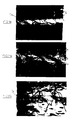
- FIGS. 11a to 11c are photographic reproductions showing the main phases of production of a patch according to the invention as described above.
- FIG. 11a corresponds to the zone of progressive introduction of the covering fibers (1a) onto the launching wire (14) (zone going from point A to point C of FIG. 10).
- FIG. 11b corresponds to the zone in which the progressive introduction of the core fibers (1b) takes place under the covering fibers (1a) to go to a double count of the normal thread count (DE zone of the figure 10).
- Figure 11c illustrates the end of the piecing (area EF) of Figure 10 in which the launch wire (14) is cut.
- Figures 12 and 13 show by way of indication two types of core fiber yarns for which the method according to the invention can be implemented. We can clearly see in these photographs the fibers (1b) forming the core and which are surrounded by the fibers (1a) forming the cover.
Landscapes
- Engineering & Computer Science (AREA)
- Mechanical Engineering (AREA)
- Textile Engineering (AREA)
- Spinning Or Twisting Of Yarns (AREA)
- Yarns And Mechanical Finishing Of Yarns Or Ropes (AREA)
Abstract
Description
La présente invention a trait à un procédé permettant de réaliser la relance et la rattache de filés de fibres comportant une âme interne, filés qui dans la suite de la description seront désignés par l'expression "filés à âme" ; elle concerne également un nouveau type de rattache réalisée grâce à un tel procédé ainsi qu'une machine de filature perfectionnée permettant de le mettre en oeuvre.The present invention relates to a process making it possible to produce and re-attach yarns of fibers comprising an internal core, yarns which in the following description will be designated by the expression "core yarns"; it also relates to a new type of piecing made using such a method as well as an improved spinning machine enabling it to be implemented.
A ce jour, de très nombreuses solutions ont été envisagées pour réaliser des filés à âme interne.To date, numerous solutions have been envisaged for producing threads with an internal core.
La plus répandue consiste à introduire une âme multifilamentaire à l'intérieur d'une mèche, lors de la dernière opération de filature, c'est-à-dire sur le continu à filer, ladite âme étant introduite en amont de la dernière paire de rouleaux d'étirage de la mèche.The most common is to introduce a multifilament core inside a wick, during the last spinning operation, that is to say on the continuous spinning, said core being introduced upstream of the last pair of wick stretching rollers.
Il a été également proposé de projeter des fibres élémentaires sur un filé formant âme, soumis à une fausse torsion passagère et ce, en amont de la broche de fausse torsion. Cette projection des fibres élémentaires sur l'âme dans la zone de remontée de torsion peut être réalisée conformément aux enseignements du brevet européen no. 085635 (correspondant au brevet US-A-4 489 540), au moyen d'une surface mobile sur laquelle lesdites fibres sont délivrées tangentiellement, ce qui permet d'exercer une force de traction sur les extrémités libres de ces fibres, l'âme étant déplacée tangentiellement par rapport à ladite surface de guidage selon une direction concurrente avec la direction d'amenée de ces fibres.It has also been proposed to project elementary fibers onto a core yarn, subjected to a temporary false twist and this, upstream of the false twist spindle. This projection of the elementary fibers onto the core in the torsion rise zone can be carried out in accordance with the teachings of European patent no. 085635 (corresponding to US-A-4,489,540), by means of a movable surface on which said fibers are delivered tangentially, which makes it possible to exert a tensile force on the free ends of these fibers, the core being moved tangentially relative to said guide surface in a direction concurrent with the direction of supply of these fibers.
Le brevet européen no. 0206 956 (correspondant au brevet US-A-4 757 680) décrit un perfectionnement apporté à une telle technique et qui permet notamment d'automatiser de telles machines et d'effectuer de manière simple, efficace et précise, l'opération de relance après casse d'un fil ou lors de toute autre intervention, voire même lors du remplacement d'une bobine pleine par un support de renvidage vide.European patent no. 0206 956 (corresponding to patent US-A-4,757,680) describes an improvement made to such a technique and which in particular makes it possible to automate such machines and to perform in a simple, efficient and precise manner, the recovery operation after breakage of a wire or during any other intervention, or even when replacing a full spool with an empty winding support.
Dans la suite de la description, la mise en oeuvre du procédé selon l'invention sera décrite pour une machine perfectionnée mettant en oeuvre les enseignements de ce dernier brevet européen 0206956 (ou US-A-4 757 680), mais il est évident que cela n'est pas limitatif et qu'un tel procédé pourra également être mis en oeuvre sous tout autre type d'installations dans lesquelles on réalise un filé complexe à âme par projection de fibres sur une âme fibreuse au cours de sa formation.In the following description, the implementation of the method according to the invention will be described for an improved machine implementing the teachings of this last European patent 0206956 (or US-A-4,757,680), but it is obvious that this is not limiting and that such a process could also be implemented in any other type of installation in which a complex core yarn is produced by projection of fibers onto a fibrous core during its formation.
D'une manière générale, les installations de filature du type précité comportent, comme cela est illustré aux figures 1, 2, 2a et 2b annexées (figures qui sont des reproductions des figures 6 à 9 du brevet européen no. 0206 956 précité), une pluralité de positions de travail identiques disposées côte à côte sur un bâti support. Chaque position de travail comprend essentiellement, disposés entre une source d'alimentation en fibres et un ensemble de réception du fil terminé (éléments non représentés aux figures 1 à 2b par mesure de simplification), un ensemble de traitement proprement dit, disposé à la sortie d'un système d'étirage (désigné par la référence générale (E)), permettant de traiter deux mèches de fibres (1a,1b), les fibres (1a) étant destinées à former la couverture du filé alors que les fibres (1b) sont destinées à former l'âme. En aval de la dernière paire de cylindres (2,3) du système d'étirage (E), sont disposés les organes permettant de réaliser les associations des fibres d'âme et de couverture, ces organes étant désignés dans la suite de la description par l'expression "bloc de filature". Un tel bloc de filature est constitué essentiellement par une surface de guidage (4) ou élément condenseur se présentant sous la forme d'un cylindre rotatif creux percé sur toute sa périphérie d'orifices (5). Le cylindre rotatif est soumis à l'action d'une source d'aspiration. Une broche de fausse torsion (6) est disposée en aval de ce guide condenseur (4). En amont du guide condenseur (4), est disposé un second élément condenseur (7) de conception similaire au condenseur (4) et qui est associé à un galet mobile (8). Grâce à un tel ensemble, compte tenu de la torsion communiquée par la broche (6) qui remonte jusqu'à la zone de pincement entre le condenseur (7) et le galet (8), on forme à l'aide des fibres (10) provenant de la mèche (1b) une âme (11). Les fibres (9) qui proviennent de la mèche (1a) et qui sont délivrées à la surface du condenseur (4) sont déposées contre la surface du fil d'âme (11) et, compte tenu du déplacement de celui-ci et de la torsion qui remonte, se trouvent bloquées autour de cette âme formant, en quelque sorte un guipage. Il convient de noter que dans une telle machine, les éléments condenseurs d'âme (7) et de couverture (4) assurent non seulement le transfert des fibres depuis la sortie du système d'étirage (E), mais également une parallélisation des fibres élémentaires (9,10) ainsi qu'un étirage additionnel fonction de leur vitesse périphérique. En réglant les vitesses périphériques desdits condenseurs (4,7), il est possible de modifier la composition du filé obtenu (modification de la proportion des fibres constituant l'âme (11) par rapport aux fibres de couverture) ainsi que le titre final.In general, spinning installations of the aforementioned type comprise, as illustrated in FIGS. 1, 2, 2a and 2b annexed (figures which are reproductions of FIGS. 6 to 9 of the aforementioned European patent no. 0206 956), a plurality of identical working positions arranged side by side on a support frame. Each working position essentially comprises, arranged between a source of fiber supply and a set for receiving the finished yarn (elements not shown in FIGS. 1 to 2b for simplification purposes), a treatment set proper, disposed at the outlet. a drawing system (designated by the general reference (E)), making it possible to treat two strands of fibers (1a, 1b), the fibers (1a) being intended to form the covering of the yarn while the fibers (1b ) are intended to form the soul. Downstream of the last pair of cylinders (2,3) of the stretching system (E), are arranged the members making it possible to make the associations of the core and covering fibers, these members being designated in the following description by the expression "block of spinning". Such a spinning block consists essentially of a guide surface (4) or condenser element in the form of a hollow rotary cylinder pierced over its entire periphery with orifices (5). The rotary cylinder is subjected to the action of a suction source. A false twist pin (6) is arranged downstream of this condenser guide (4). Upstream of the condenser guide (4), is arranged a second condenser element (7) of a design similar to the condenser (4) and which is associated with a movable roller (8). Thanks to such an assembly, taking into account the twist communicated by the spindle (6) which rises to the nip between the condenser (7) and the roller (8), it is formed using fibers (10 ) from the wick (1b) a core (11). The fibers (9) which come from the wick (1a) and which are delivered to the surface of the condenser (4) are deposited against the surface of the core wire (11) and, taking account of the displacement of the latter and of the twisting which goes up, are blocked around this soul forming, in a way a covering. It should be noted that in such a machine, the core (7) and cover (4) condensing elements not only ensure the transfer of the fibers from the outlet of the drawing system (E), but also a parallelization of the fibers. elementary (9,10) as well as an additional stretching function of their peripheral speed. By adjusting the peripheral speeds of said condensers (4,7), it is possible to modify the composition of the yarn obtained (modification of the proportion of the fibers constituting the core (11) relative to the covering fibers) as well as the final titer.
Dans un tel bloc de filature, l'élément condenseur de couverture (élément 4) et l'élément condenseur d'âme (élément 7), la broche de fausse torsion (6) et le système d'appel (13) du filé (14) formé, sont regroupés sur un boitier commun désigné par la référence générale (15) à la figure 2 sous la forme d'un ensemble compact. Par ailleurs, sur ce boitier, entre la sortie du système d'étirage (2,3) et la surface du condenseur (4,7), sont disposés des éléments séparateurs (16,17,18) formant des canaux de guidage permettant de bien canaliser les fibres élémentaires (9,10) des mèches (1a,1b), évitant non seulement des pertes de fibres, mais également toute perturbation entre les deux flux fibreux.In such a spinning block, the covering condenser element (element 4) and the core condenser element (element 7), the false twist spindle (6) and the yarn calling system (13) ( 14) formed, are grouped on a common box designated by the general reference (15) in Figure 2 in the form of a compact assembly. Furthermore, on this box, between the outlet of the stretching system (2,3) and the surface of the condenser (4,7), are arranged separating elements (16,17,18) forming guide channels allowing channel the elementary fibers (9,10) of the wicks (1a, 1b) well, avoiding not only fiber losses, but also any disturbance between the two fibrous flows.
Afin de permettre l'automatisation d'une telle machine de filature, le Demandeur a proposé différentes solutions concernant, d'une part le système d'étirage (E) (FR-A-2 619 630 correspondant à l'US-A-4 878 268), et d'autre part, la broche de fausse torsion (6) que comporte le bloc de filature proprement dit (FR-A-2 619 831 correspondant à l'US-A-4 910 953). L'application de ces systèmes d'étirage et de fausse torsion à une machine du type illustré par les figures 1 et 2 permet de réaliser des ensembles qui peuvent être facilement automatisées, non seulement lors d'une relance après enlèvement d'une bobine pleine, mais également lorsque l'on souhaite effectuer les opérations de relance à la suite d'une casse ou de tout autre défaut produit lors de la production. Cependant, lors de ces opérations de relance, se pose le problème de réaliser une rattache résistante et qui ne présente pas de défaut (ou un minimum de défauts acceptables).In order to allow the automation of such a spinning machine, the Applicant has proposed different solutions relating, on the one hand, to the stretching system (E) (FR-A-2 619 630 corresponding to US-A- 4,878,268), and on the other hand, the false twist spindle (6) that comprises the actual spinning block (FR-A-2,619,831 corresponding to US-A-4,910,953). The application of these stretching and false twist systems to a machine of the type illustrated in FIGS. 1 and 2 makes it possible to produce assemblies which can be easily automated, not only during a restart after removal of a full reel , but also when you want to carry out the recovery operations following a breakage or any other defect produced during production. However, during these recovery operations, the problem arises of making a resistant connection that does not present any defect (or a minimum of acceptable defects).
A ce jour, les solutions classiques pour réaliser de telles rattaches (par exemple nouage, collage, épissure, entrelaçage..), impliquent généralement que les deux extrémités à réunir soient immobiles, ce qui entraîne soit une interruption dans le processus de fonctionnement de la machine, soit la présence d'éléments de stockage de fils en amont et en aval de la zone où est effectuée la rattache. Ces solutions classiques de rattache peuvent être utilisées pour la mise en oeuvre de la machine précitée, mais les inconvénients qu'elles présentent se trouvent accentués par le fait que le fil formé est à base de deux constituants (1a,1b) amenés séparément sur les éléments condenseurs (4,7). Par ailleurs, une telle installation pouvant fonctionner à des vitesses de production très élevées (plusieurs centaines de mètres par minute), la relance ne peut pas être réalisée à pleine vitesse de fonctionnement et, implique, comme dans toutes les installations textiles fonctionnant à des vitesses élevées, de prévoir soit l'arrêt soit une marche à vitesse lente qui, obligatoirement, entraîne donc des variations dans les caractéristiques du fil produit lors de cette phase de lancement.To date, conventional solutions for making such connections (for example knotting, gluing, splicing, interlacing, etc.) generally imply that the two ends to be joined are immobile, which results in either an interruption in the operating process of the machine, or the presence of wire storage elements upstream and downstream of the area where the reattachment is carried out. These conventional piecing solutions can be used for the implementation of the aforementioned machine, but the disadvantages that they present are accentuated by the fact that the wire formed is based on two constituents (1a, 1b) brought separately on the condensing elements (4,7). Furthermore, since such an installation can operate at very high production speeds (several hundred meters per minute), recovery cannot be carried out at full operating speed and, as in all textile installations operating at speeds, implies provide for either stopping or walking at slow speed, which necessarily results in variations in the characteristics of the yarn produced during this launch phase.
Or on a trouvé, et c'est ce qui fait l'objet de la présente invention, qu'il était possible de résoudre ces problèmes de relance et de rattache grâce à un nouveau procédé qui, non seulement permet d'effectuer des rattaches de très bonne qualité, mais également permet de réaliser cette opération à pleine vitesse de fonctionnement de la machine et ce, aussi bien manuellement que de manière complètement automatisée.Now it has been found, and this is what is the subject of the present invention, that it was possible to solve these problems of recovery and piecing through a new process which, not only allows to perform piecing of very good quality, but also allows this operation to be carried out at full operating speed of the machine, both manually and completely automatically.
D'une manière générale, le procédé de relance et rattache conforme à l'invention lors d'une opération de filature sur une machine permettant de réaliser un filé de fibres à âme, se caractérise en ce qu'il comporte la succession des opérations suivantes :
- prélèvement d'une longueur de fil préalablement formé à partir du support de renvidage ;
- mise en réserve d'une longueur de fil ainsi prélevé à l'intérieur d'un ensemble de stockage ;
- introduction sous la forme d'un brin tendu d'une partie du fil ainsi mis en réserve à l'intérieur de l'ensemble des organes permettant la réalisation du filé à âme ;
- remise en route de l'ensemble de renvidage et embrayage des organes des blocs de traitement, les fibres provenant du système d'étirage (E) étant mises aux déchets ;
- au cours de l'avance du fil d'amorce sur les organes de filature :
. dans un premier temps, arrêt de la mise aux déchets des fibres destinées à former la couverture du filé à âme et distribution de ces fibres sur le fil d'amorçage en mouvement,
. dans un deuxième temps, arrêt de la mise aux déchets des fibres destinées à former l'âme du filé à âme, et distribution de ces fibres sur le fil d'amorce en mouvement qui est alors coupé entre la sortie de la réserve et l'entrée à l'intérieur du bloc de filature.In general, the recovery and reattachment method according to the invention during a spinning operation on a machine making it possible to produce a yarn of core fibers, is characterized in that it comprises the succession of the following operations:
- sampling of a length of yarn previously formed from the winding support;
- setting aside a length of wire thus taken from inside a storage assembly;
- Introduction in the form of a stretched strand of part of the yarn thus set aside inside all of the members allowing the making of the core yarn;
- restarting of the winding and clutch assembly of the bodies of the processing blocks, the fibers coming from the drawing system (E) being put into waste;
- during the advance of the starter thread on the spinning members:
. firstly, the end of the disposal of the fibers intended to form the cover of the core yarn and distribution of these fibers on the moving initiation wire,
. in a second step, stopping the waste disposal of the fibers intended to form the core of the core spun, and distribution of these fibers on the moving starter wire which is then cut between the outlet of the reserve and the entry inside the spinning block.
En d'autres termes selon l'invention, contrairement à la logique qui conduirait à effectuer la relance en suivant le processus normal de réalisation du filé à âme, c'est-à-dire formation de l'âme puis dépôt des fibres de couverture, on inverse le processus lors de l'opération de rattache en commençant par déposer les fibres de couverture puis les fibres d'âme sur le fil de relance, le positionnement correct de ces fibres les unes par rapport aux autres en marche normale se faisant automatiquement dès que l'on arrive à l'extrémité coupée du fil de relance.In other words according to the invention, contrary to the logic which would lead to carrying out the recovery by following the normal process of production of the core spun, that is to say formation of the core then deposition of the covering fibers , we reverse the process during the reattachment operation by first depositing the covering fibers and then the core fibers on the recovery wire, the correct positioning of these fibers relative to each other. to others in normal operation being done automatically as soon as one arrives at the cut end of the stimulus wire.
Eventuellement, lors de la réalisation de cette rattache, pour éviter le coup de fouet qui peut se produire lorsque le fil d'amorce est coupé, un dispositif d'abrasion superficiel permettant un affinage de l'extrémité du fil de lancement est prévu et est mis en oeuvre lorsque le débit fibreux destiné à former l'âme est amorcé.Optionally, when making this connection, to avoid the whiplash that can occur when the leader wire is cut, a surface abrasion device allowing a refinement of the end of the launching wire is provided and is implemented when the fibrous flow intended to form the core is initiated.
Grâce à un tel procédé, on obtient donc une rattache dont la structure est telle que, si l'on considère le début de la jonction entre le fil de lancement et les fibres destinées à constituer le fil à âme :
- que tout d'abord, ce fil de lancement est recouvert par les fibres destinées à former la couverture du filé à âme ;
- qu'ensuite, ces fibres de couverture recouvrent les fibres destinées à former l'âme et ;
- qu'au niveau de l'extrémité du fil de lancement, les fibres élémentaires de couverture et d'âme s'interpénètrent de manière à constituer le filé à âme normal destiné à être produit.Thanks to such a method, a connection is therefore obtained, the structure of which is such that, if we consider the start of the junction between the launching wire and the fibers intended to constitute the core wire:
- First of all, this launching thread is covered by the fibers intended to form the cover of the core yarn;
- Then, these covering fibers cover the fibers intended to form the core and;
- At the end of the launching wire, the elementary cover and core fibers interpenetrate so as to constitute the normal core yarn intended to be produced.
Le procédé selon l'invention peut être mis en oeuvre aussi bien lorsque l'on souhaite réaliser une rattache suite à une casse du fil (soit accidentelle, soit provoquée pour éliminer un défaut) au cours de sa production, qu'éventuellement lorsque l'on souhaite relancer la machine en remplaçant une bobine pleine par un tube support vide, auquel cas ce dernier comportera alors quelques mètres de fil préalablement formés et enroulés autour de lui.The method according to the invention can be implemented both when it is desired to make a connection following a breakage of the wire (either accidental or caused to eliminate a defect) during its production, and possibly when the we want to restart the machine by replacing a full coil with an empty support tube, in which case the latter will then include a few meters of wire previously formed and wound around it.
Un tel procédé peut être mis en oeuvre sur une machine perfectionnée du type réalisé conformément aux enseignements de l'EP-206 956 (ou US-A-4 757 680) grâce à la combinaison des moyens suivants :
- a) adaptation de la structure du "bloc de filature" (condenseur (7) et galet bloqueur (8), condenseur de couverture (4), broche de fausse torsion (6) et délivreur d'appel (13)) pour que le fil puisse, lors du lancement être introduit par déplacement latéral à l'intérieur de ces éléments ;
- b) association à ce bloc de filature un ensemble de stockage d'une réserve de fil, disposé en dessous du plan dit "plan de filature" et qui correspond au plan passant par la surface de contact entre les courroies de la broche de fausse torsion (6) et qui est tangent à la surface des condenseurs (7,4) et du cylindre (13a) du délivreur d'appel de sortie (13) ; un tel "plan de filature" n'est pas à proprement parler une surface plane, étant donné qu'il suit le trajet du fil au cours de sa formation entre ces éléments et que ce trajet n'est pas obligatoirement rectiligne, le fil pouvant former un léger embarrage autour du condenseur (4) ainsi qu'entre les courroies (6a,6b) de la broche et ;
- c) adaptation du cycle de fonctionnement de l'installation pour que, au moment de la relance, on introduise à l'intérieur des organes de traitement un fil de relance préalablement formé et qui a été prélevé à partir du support de renvidage pour être stocké à l'intérieur de la réserve et que la dépose des fibres soit réalisée, lors de la remise en route de l'ensemble de renvidage en distribuant tout d'abord sur le fil de relance en mouvement les fibres destinées à former la couverture du filé, puis, avec un léger retard, les fibres destinées à former l'âme, le fil de relance en mouvement étant alors coupé entre la sortie de la réserve et l'entrée à l'intérieur du bloc de filature.
- a) adaptation of the structure of the "spinning block" (condenser (7) and blocking roller (8), cover condenser (4), false twist spindle (6) and call deliverer (13)) so that the wire can, during launching be introduced by lateral displacement inside these elements;
- b) association with this spinning block a set of storage of a thread reserve, arranged below the plane called "spinning plane" and which corresponds to the plane passing through the contact surface between the belts of the false twist spindle (6) and which is tangent to the surface of the condensers (7,4) and of the cylinder (13a) of the outgoing call provider (13); such a "spinning plane" is not strictly speaking a flat surface, given that it follows the path of the wire during its formation between these elements and that this path is not necessarily rectilinear, the wire being able to form a slight interlock around the condenser (4) as well as between the belts (6a, 6b) of the spindle and;
- c) adaptation of the operating cycle of the installation so that, at the time of the revival, a stimulus wire previously formed and which has been taken from the winding support to be stored is introduced inside the treatment members inside the reserve and that the fibers are removed, when the winding assembly is restarted by first distributing the fibers intended to form the cover of the yarn on the moving stimulus wire , then, with a slight delay, the fibers intended to form the core, the stimulus wire in motion then being cut between the outlet of the reserve and the inlet inside the spinning block.
Pour faciliter l'introduction du fil à l'intérieur des organes de traitement lors d'une relance dans une telle machine ainsi perfectionnée, le galet rotatif (8) et l'un des cylindres d'appel du délivreur de sortie (13), dans le cas présent le cylindre d'appel (13a), sont débordants par rapport aux autres éléments du bloc de filature (condenseur d'âme, condenseur de couverture et broche de fausse torsion) ; par ailleurs, les condenseurs d'âme et de couverture présentent une face avant de forme conique.To facilitate the introduction of the wire inside the processing members during a revival in such a machine thus improved, the rotary roller (8) and one of the call cylinders of the output deliverer (13), in the present case the call cylinder (13a), are projecting with respect to the other elements of the spinning block (core condenser, cover condenser and false twist spindle); furthermore, the core and cover condensers have a conical front face.
Enfin, l'ensemble de stockage de la réserve de fil se présente de préférence sous la forme d'un tube aspirant associé à un élément mobile, coulissant à l'intérieur du tube, permettant ainsi non seulement d'amener le fil à l'intérieur du plan de travail, mais facilitant également le prélèvement du fil stocké à l'intérieur de la réserve et son introduction dans les différents éléments du bloc de traitement.Finally, the storage assembly for the wire reserve is preferably in the form of a suction tube associated with a mobile element, sliding inside the tube, thus making it possible not only to bring the wire to the inside the work plan, but also facilitating the removal of the wire stored inside the reserve and its introduction into the different elements of the processing block.
Dans une telle machine, le procédé conforme à l'invention consiste, lors de l'opération de rattache (après une casse ou éventuellement lors du remplacement d'une bobine pleine par un tube support vide), à :
- prélever une longueur de fil préalablement formé à partir du support de renvidage (dans le cas où le procédé serait mis en oeuvre lors de la relance de la machine en remplaçant une bobine pleine par un support vide, ce dernier comportera quelques mètres de fil préalablement formé) ;
- stocker ledit fil ainsi prélevé à l'intérieur de la réserve disposée en-dessous du plan de filature entre le premier condenseur et la broche de fausse torsion, le trajet du fil depuis la bobine de renvidage jusqu'à l'entrée de la réserve étant réalisé de telle sorte que la portion de fil forme une boucle entourant le galet rotatif associé au condenseur d'âme, et le galet allongé du délivreur d'appel situé en aval du bloc de traitement ; - introduire une portion de fil tendu entre ces deux éléments allongés, pratiquement instantanément à l'intérieur de chacun des organes du bloc de filature, cette introduction étant réalisée avec défilement du fil avec sa vitesse de traitement en commençant par mettre le fil en réserve entre le condenseur d'âme et son galet presseur, et en déplaçant ledit fil automatiquement sur la génératrice dudit galet presseur allongé, ce qui provoque un déplacement en hélice à pas variable sur ce galet, permettant l'introduction automatique instantanée de la portion du fil entre les deux courroies de la broche de fausse torsion et l'amenant sur le condenseur de couverture ainsi qu'entre les deux cylindres du délivreur de sortie disposés en aval du bloc de filature et ;
- après mise en place à l'intérieur des éléments du bloc de traitement de ce fil de réserve et embrayage des différents organes, à délivrer, dans un premier temps les fibres de couverture sur le fil d'amorce, puis les fibres formant l'âme, la portion restante de fil de lancement contenue à l'intérieur de la réserve étant coupée sensiblement simultanément à l'amorce de la dépose des fibres destinées à former l'âme au cours de la production normale.In such a machine, the method according to the invention consists, during the reattachment operation (after a breakage or possibly when replacing a full coil with an empty support tube), at:
- take a length of wire previously formed from the winding support (in the case where the process would be implemented when restarting the machine by replacing a full spool with an empty support, the latter will include a few meters of thread beforehand trained);
store said thread thus taken inside the reserve arranged below the spinning plane between the first condenser and the false twist spindle, the path of the thread from the winding reel to the entry of the reserve being produced so that the portion of wire forms a loop surrounding the rotary roller associated with the core condenser, and the elongated roller of the call deliverer located downstream of the processing block; - Introduce a portion of yarn stretched between these two elongated elements, practically instantaneously inside each of the bodies of the spinning block, this introduction being carried out with the yarn running with its processing speed, starting by placing the yarn in reserve between the core condenser and its pressure roller, and by moving said wire automatically on the generator of said elongated pressure roller, which causes a helical displacement with variable pitch on this roller, allowing the instantaneous automatic introduction of the portion of the wire between the two belts of the false twist spindle and bringing it to the cover condenser as well as between the two cylinders of the output deliverer arranged downstream of the spinning block and;
- after installation inside the elements of the processing block of this reserve wire and clutching of the various members, to deliver, firstly, the covering fibers on the leader wire, then the fibers forming the core, the remaining portion of launching wire contained inside the reserve being cut substantially simultaneously with the initiation of the deposition of fibers intended to form the core during normal production.
Si un tel procédé peut être mis en oeuvre manuellement, le prélèvement du fil sur l'élément de renvidage pouvant être réalisé au moyen d'un ensemble aspirant (pistolet) que l'opérateur déplace pour entourer les deux éléments allongés (rouleau presseur et rouleau d'appel), et amener le fil à l'entrée de la réserve, une telle machine et un tel procédé sont facilement automatisables par exemple, soit en prévoyant sur chaque position de la machine un ensemble dit "écarteur" permettant de disposer le fil en forme de boucle autour des éléments précités, soit en prévoyant un tel élément écarteur sur un robot, déplaçable devant la machine et commun à toutes les positions de travail.If such a method can be carried out manually, it is possible to take the thread from the winding element by means of a suction assembly (gun) which the operator moves to surround the two elongated elements (pressure roller and roller call), and bring the wire to the entrance of the reserve, such a machine and such a process can be easily automated for example, either by providing on each position of the machine a set called "spacer" allowing to have the wire in the form of a loop around the aforementioned elements, either by providing such a spacer element on a robot, movable in front of the machine and common to all the working positions.
Par ailleurs, pour la mise en oeuvre du procédé conforme à l'invention, les canaux de guidage des flux fibreux d'âme et de couverture disposés entre la sortie du système d'étirage et la surface des éléments condenseurs d'âme et de couverture sont associés à des moyens d'aspiration permettant la mise aux déchets des fibres pendant la phase préparatoire au lancement, cette aspiration étant supprimée, selon une séquence programmée et déterminée lors du lancement proprement dit, de telle sorte que les fibres de couverture soient déposées sur le fil de relance préalablement au dépôt des fibres destinées à former l'âme.Furthermore, for the implementation of the method according to the invention, the channels for guiding the fibrous fluxes of core and covering arranged between the outlet of the drawing system and the surface of the condensing elements of core and covering are associated with suction means allowing the waste to be put into the fibers during the preparatory phase for launching, this aspiration being eliminated, according to a programmed sequence and determined during the launching proper, so that the covering fibers are deposited on the recovery wire prior to the deposition of the fibers intended to form the core.
Lorsque la relance est effectuée, le fil mis en réserve est coupé automatiquement.When the restart is carried out, the wire placed in reserve is cut automatically.
Des moyens additionnels peuvent être prévus pour améliorer la qualité de la rattache, tels que par exemple des moyens permettant d'affiner le fil de relance.Additional means can be provided to improve the quality of the piecing, such as for example means making it possible to refine the stimulus wire.
Un tel processus de relance et rattache conforme à l'invention sera cependant mieux compris grâce à la suite de la description et à l'exemple de réalisation donné ci-après à titre indicatif mais non limitatif, et qui est illustré par les schémas annexés dans lesquels :Such a relaunching and linking process in accordance with the invention will however be better understood thanks to the following description and to the example of embodiment given below by way of indication but not limitation, and which is illustrated by the diagrams appended in which :
- les figures 1 à 2a illustrent, comme décrit précédemment, l'état de la technique constitué par une position de travail d'une machine de filature réalisée conformément aux enseignements du brevet européen 0 206 956 (US-A-4 757 680) :
- . la figure 1 étant une vue en perspective schématique montrant la dernière paire des cylindres du système d'étirage (E) et le bloc de filature proprement dit ;
- . la figure 2 étant une vue frontale d'une telle position de travail et,
- . les figures 2a et 2b étant des vues de côté montrant respectivement selon les directions B et C de la figure 2 :
x l'étirage de la mèche de fibres d'âme, le condenseur et le galet bloqueur associé à ce condenseur pour former le fil d'âme (figure 2a) ;
x l'étirage de la mèche de fibres de couverture et le condenseur sur lequel les fibres de cette mèche sont délivrées afin de permettre leur association avec le fil d'âme en formation (figure 2b) ; - - la figure 3 est une vue schématique de face montrant les adaptations apportées à une telle position de travail pour faciliter la mise en oeuvre du procédé conforme à l'invention ;
- - la figure 4 est une vue de dessus de cette position de travail adaptée pour la mise en oeuvre du procédé selon l'invention ;
- - les figures 5
et 6 sont des schémas, vus de face, montrant la manière dont est prélevé le fil sur la bobine réceptrice et dont il est positionné autour des éléments du bloc de filature lors de l'opération de relance ; - - la figure 7 est une vue schématique de côté montrant la manière dont est prélevé le fil sur la bobine formée lorsque l'on effectue la relance ;
- - la figure 8 est une vue schématique en perspective de la courroie supérieure de la broche de fausse torsion utilisée dans la machine conforme à l'invention et montrant comment est réintroduit le fil à l'intérieur de cette broche lors de la relance ;
- - les figures 9a à 9n illustrent l'ensemble du processus opératoire selon l'invention pour la relance d'une position de travail sur une machine de filature adaptée pour la mise en oeuvre d'un tel processus ;
- - la figure 10 illustre, de manière schématique, la structure d'une rattache réalisée conformément à l'invention ;
- - les figures 11a,11b et 11c sont des reproductions de photographies montrant les trois phases principales de réalisation d'une rattache réalisée conformément au procédé selon l'invention ;
- - les figures 12 et 13 sont des reproductions de photographies de deux filés à âme pour lesquels le procédé de rattache conforme à l'invention est particulièrement adapté.
- . Figure 1 being a schematic perspective view showing the last pair of cylinders of the drawing system (E) and the spinning block itself;
- . FIG. 2 being a front view of such a working position and,
- . FIGS. 2a and 2b being side views showing respectively in directions B and C of FIG. 2:
x stretching the core fiber wick, the condenser and the blocking roller associated with this condenser to form the core wire (FIG. 2a);
x stretching the strand of covering fibers and the condenser on which the fibers of this strand are delivered in order to allow their association with the core wire being formed (FIG. 2b); - - Figure 3 is a schematic front view showing the adaptations made to such a working position to facilitate the implementation of the method according to the invention;
- - Figure 4 is a top view of this working position suitable for the implementation of the method according to the invention;
- - Figures 5 and 6 are diagrams, seen from the front, showing the way in which the yarn is taken from the take-up reel and how it is positioned around the elements of the spinning block during the restarting operation;
- - Figure 7 is a schematic side view showing the way in which the wire is taken from the spool formed when the recovery is carried out;
- - Figure 8 is a schematic perspective view of the upper belt of the false twist spindle used in the machine according to the invention and showing how the thread is reintroduced inside this spindle during the restart;
- - Figures 9a to 9n illustrate the entire operating process according to the invention for reviving a working position on a spinning machine adapted for the implementation of such a process;
- - Figure 10 illustrates, schematically, the structure of a connection made in accordance with the invention;
- - Figures 11a, 11b and 11c are reproductions of photographs showing the three main phases of production of a connection produced in accordance with the method according to the invention;
- - Figures 12 and 13 are reproductions of photographs of two core yarns for which the joining process according to the invention is particularly suitable.
Dans la suite de la description, le procédé selon l'invention et sa mise en oeuvre seront décrits en se référant plus particulièrement aux figures 3 à 9n qui, comme dit précédemment, illustrent les adaptations apportées à une position de travail d'une machine permettant la réalisation d'un filé à âme telle qu'illustrée aux figures 1 à 2b.In the following description, the method according to the invention and its implementation will be described with particular reference to Figures 3 to 9n which, as said above, illustrate the adaptations made to a working position of a machine allowing making a core spun as illustrated in Figures 1 to 2b.
Si l'on se reporte aux schémas annexés, en utilisant les mêmes références que celles employées pour décrire l'état de la technique antérieur illustré par les figures 1 à 2b, une position de travail d'une machine conforme à l'invention comporte un système d'étirage E, commun aux deux mèches de fibres (1a,1b) destinées à former respectivement la couverture et l'âme du fil. Ce système d'étirage est disposé de préférence verticalement ou sensiblement verticalement sur le bâti de la machine. En-dessous du système d'étirage E, est disposé le bloc de filature proprement dit dont les différents organes sont montés sur un boitier support non représenté par mesure de simplification. Ce bloc de filature comporte, disposé immédiatement en-dessous de la dernière paire de cylindres (2,3) du système d'étirage E, un ensemble d'éléments séparateurs (16,17,18) formant des canaux de guidage (19,20) pour les flux de fibres sortant du système d'étirage E. Comme la machine conforme à l'invention fonctionne exactement de la même manière que celle décrite dans le brevet européen précité, les flux de fibres élémentaires (9,10) formant la couverture et l'âme ne sont pas représentés par mesure de simplification. Ces éléments séparateurs (16,17,18) et les canaux (19) qu'ils définissent entre eux sont constitués par exemple par une pièce usinée monobloc qui vient envelopper sur une partie de leur périphérie les éléments condenseurs (4,7) des fibres de couverture et d'âme. L'ensemble du bloc de filature est réalisé d'une manière similaire à l'exemple illustré par la figure 5 du brevet européen no. 206956, si ce n'est, comme cela sera vu dans la suite de la description, que les organes qui le composent sont adaptés pour permettre une automatisation de la machine pour réaliser les opérations de relance. D'une manière générale, ces adaptations résident essentiellement, ainsi que cela ressort de la vue de dessus (figure 4), par une augmentation de la longueur du galet bloqueur de torsion (8), de telle sorte qu'il déborde sur l'avant par rapport au condenseur d'âme (7) et au condenseur de couverture (4), à la broche (6), l'un des galets du délivreur de sortie (13), dans le cas présent le galet (13a), étant également allongé pour déborder vers l'avant d'une manière similaire au galet (8). La broche de fausse torsion (6) disposée en aval du condenseur de couverture (4) est, quant à elle, réalisée conformément aux enseignements du brevet français no. 2 619 831. Dans une telle machine, l'amenée des mèches de fibres à traiter (mèches 1a,1b) et l'extraction du fil formé (14) en sortie du délivreur (13) sont réalisées en sens inverse dans un plan vertical ou sensiblement vertical, alors que le trajet de la matière à l'intérieur du bloc de filature est réalisé soit horizontalement, soit de préférence dans un plan légèrement incliné dans plan P dit "plan de filature" qui passe par la ligne de pincement entre le condenseur d'âme (7) et le galet (8), le point de tangence du fil en cours de formation à la surface du condenseur (4), entre les deux courroies (6a,6b) de la broche de fausse torsion (6) et le point de contact du fil avec le galet (13a) du délivreur de sortie (13). Ainsi que cela ressort des figures 3 et 5, le plan de filature n'est pas une véritable surface plane, le fil venant légèrement embarrer contre le condenseur de couverture (4) et la surface des courroies (6).If reference is made to the appended diagrams, using the same references as those used to describe the state of the prior art illustrated in FIGS. 1 to 2b, a working position of a machine according to the invention comprises a drawing system E, common to the two wicks of fibers (1a, 1b) intended to form the cover and the core of the wire respectively. This stretching system is preferably arranged vertically or substantially vertically on the machine frame. Below the stretching system E, the spinning block proper is arranged, the various members of which are mounted on a support box not shown for simplification. This spinning block comprises, arranged immediately below the last pair of cylinders (2,3) of the stretching system E, a set of separating elements (16,17,18) forming guide channels (19, 20) for the fiber flows leaving the drawing system E. As the machine according to the invention operates in exactly the same way as that described in the aforementioned European patent, the elementary fiber flows (9, 10) forming the cover and core are not shown for simplicity. These separating elements (16, 17, 18) and the channels (19) which they define between them are constituted for example by a monobloc machined part which comes to wrap on a part of their periphery the condensing elements (4,7) of the fibers. of cover and soul. The entire spinning block is produced in a similar manner to the example illustrated in FIG. 5 of European patent no. 206956, if not, as will be seen in the following description, that the members that compose it are adapted to allow automation of the machine to perform the recovery operations. In general, these adaptations reside essentially, as is apparent from the top view (FIG. 4), by an increase in the length of the torsion blocking roller (8), so that it extends beyond the front with respect to the core condenser (7) and the covering condenser (4), to the spindle (6), one of the rollers of the output deliverer (13), in this case the roller (13a), also being elongated to extend forward in a manner similar to the roller (8). The false twist spindle (6) disposed downstream of the covering condenser (4) is, in turn, produced in accordance with the teachings of French patent no. 2,619,831. In such a machine, the feeding of the wicks of fibers to be treated (
Par ailleurs, conformément à l'invention, un ensemble de stockage (20) d'une réserve de longueur de fil est disposé en-dessous du plan P précité. Cet ensemble de stockage schématisé à la figure 4 est constitué essentiellement par un tube aspirant (21) et est associé à un ensemble mobile (22) dit "vérin de lancement" et qui permet, ainsi que cela sera vu dans la suite de la description, lors du lancement, l'introduction du fil à l'intérieur des différents éléments constituant le bloc de filature et, simultanément l'extraction du fil stocké à l'intérieur de ladite réserve. Cet élément mobile (22) est constitué par un tube coulissant à l'intérieur de l'extrémité d'entrée de la réserve (20).Furthermore, in accordance with the invention, a storage assembly (20) for a reserve of wire length is arranged below the above-mentioned plane P. This storage assembly shown diagrammatically in FIG. 4 consists essentially of a suction tube (21) and is associated with a mobile assembly (22) called "launching cylinder" and which allows, as will be seen in the following description , during launching, the introduction of the yarn inside the different elements constituting the spinning block and, simultaneously, the extraction of the yarn stored inside said reserve. This mobile element (22) consists of a sliding tube inside the inlet end of the reserve (20).
Afin de pouvoir réaliser l'opération de lancement automatiquement, le galet bloqueur de torsion (8) associé au condenseur d'âme (7) ainsi que le galet (13a) du délivreur de sortie (13) ont une longueur telle qu'ils débordent sur l'avant par rapport aux autres éléments du bloc de filature.In order to be able to carry out the launching operation automatically, the torsion blocking roller (8) associated with the core condenser (7) as well as the roller (13a) of the output deliverer (13) have a length such that they overflow on the front compared to the other elements of the spinning block.
Par ailleurs, afin de faciliter l'introduction du fil à l'intérieur des différents éléments, les faces d'entrée des condenseurs (7) et (4) sont de forme conique et la broche de fausse torsion (6) est associée à une rampe (23) qui, lors de l'introduction du fil, amène ce dernier contre la courroie supérieure (6a) de la broche (6) afin de faciliter sa mise en place (voir figure 8).Furthermore, in order to facilitate the introduction of the wire inside the various elements, the inlet faces of the condensers (7) and (4) are of conical shape and the false twist pin (6) is associated with a ramp (23) which, during the introduction of the wire, brings the latter against the upper belt (6a) of the spindle (6) in order to facilitate its positioning (see FIG. 8).
Enfin, chaque position de travail comporte, et cela est représenté uniquement à la figure 3, des moyens d'aspiration (24,25) associés à chaque condenseur (4,7) et qui permettent une mise aux déchets des fibres des mèches (1a,1b) tant que le processus normal de fonctionnement n'est pas mis en oeuvre.Finally, each working position comprises, and this is shown only in FIG. 3, suction means (24.25) associated with each condenser (4.7) and which allow the fibers of the wicks (1a) to be disposed of. , 1b) until the normal operating process is implemented.
Des moyens permettant d'affiner le fil de relance peuvent être également associés au bloc de filature, ces moyens d'affinage étant constitués par une surface abrasive (27) (voir figure 3) disposée en amont de la ligne de pincement entre le condenseur d'ame (7) et le galet (8), et qui est constituée par exemple par un feuillard flexible. Cet élément (27) permet non seulement d'affiner l'extrémité du fil de relance lors de la phase finale du processus, et évite également que l'extrémité libre du fil de relance après coupe ne forme un défaut.Means for refining the stimulus wire can also be associated with the spinning block, these refining means being constituted by an abrasive surface (27) (see FIG. 3) disposed upstream of the nip between the condenser d 'core (7) and the roller (8), and which is constituted for example by a flexible strip. This element (27) not only makes it possible to refine the end of the recovery wire during the final phase of the process, and also prevents the free end of the recovery wire after cutting from forming a defect.
Grâce à une telle structure de machine, il est possible de réaliser les opérations de relance d'une position de manière particulièrement simple et rapide, cette opération pouvant être réalisée soit manuellement, soit de préférence automatiquement.Thanks to such a machine structure, it is possible to carry out the operations for relaunching a position in a particularly simple and rapid manner, this operation being able to be carried out either manually or preferably automatically.
Un tel processus de relance automatique est illustré d'une part par les figures 5,6,7,8 et, d'autre part, par les figures (9a) à (9n) qui en illustrent schématiquement les principales séquences. Dans la suite de la description, l'invention sera décrite en réalisant l'opération de relance et rattache de manière automatisée, seules les principales fonctions du robot utilisé étant décrites, cet ensemble robotisé étant simplement schématisé par les déplacements qu'il permet de réaliser pour prélever le fil sur la bobine de renvidage et le réintroduire à l'intérieur du bloc de filature ainsi que les fonctions à remplir lors de la phase d'arrêt et de remise en route.Such an automatic restart process is illustrated on the one hand by Figures 5,6,7,8 and, on the other hand, by Figures (9a) to (9n) which illustrate schematically the main sequences. In the following description, the invention will be described by carrying out the relaunch operation and reattaching in an automated manner, only the main functions of the robot used being described, this robotic assembly being simply shown diagrammatically by the displacements which it makes it possible to carry out. to take the yarn from the take-up reel and reintroduce it inside the spinning block as well as the functions to be performed during the stop and restart phase.
D'une manière générale, le processus opératoire de relance que permet la machine conforme à l'invention peut être résumé en deux phases opératoires principales, à savoir :
- a) première phase de séquence d'arrêt suite à la détection et la casse du fil, cette casse pouvant être soit accidentelle, soit provoquée par suite de la détection d'un défaut ;
- b) deuxième phase de séquence de relance et remise en route proprement dite.
- a) first phase of the stop sequence following the detection and breakage of the wire, this breakage being either accidental or caused as a result of the detection of a fault;
- b) second phase of recovery sequence and restart itself.
Lors de la séquence d'arrêt suite à une casse, on effectue les opérations suivantes illustrées de manière schématique par les figures 6 et 7 :
- après détection de la casse entre le délivreur de sortie (13) et le système de bobinage désigné par la référence générale (25), détection réalisée au moyen de tout élément connu, on provoque l'ouverture du bras d'étirage (E) ainsi que l'écartement des deux courroies (6a,6b) de la broche de fausse torsion (6) et ce, de manière très rapide afin de limiter l'encrassement des condenseurs (7,4) et la détérioration des lanières des broches ;
- après ouverture, on réalise alors le relevage de la bobine (25) de son système d'entraînement (26) ou arrêt du système d'entraînement ; ce relevage est de l'ordre de quelques millimètres par rapport au cylindre moteur (26) et est réalisé au moyen d'un dispositif permettant d'avoir un écartement (e) constant et identique quel que soit le diamètre de l'enroulement (25) ; cette opération est réalisée très rapidement afin d'éviter "d'enterrer" l'extrémité du fil formé à l'intérieur de la bobine (25) ; la bobine étant relevée, le système d'étirage E débrayé, les arbres d'étirage, les cylindres de bobinage et la came de va-et-vient (27) peuvent continuer leur mouvement si leur commande n'est pas réalisée de manière individuelle par position ;
- l'ouverture du bras d'étirage E, de la broche (6) et le relevage de la bobine (25) étant réalisés, on arrête la rotation du condenseur d'âme (7), du condenseur de couverture (4), de la broche de fausse torsion (6) et du délivreur d'appel (13).During the stop sequence following a break, the following operations are carried out, illustrated diagrammatically in FIGS. 6 and 7:
- after detection of breakage between the output deliverer (13) and the winding system designated by the general reference (25), detection carried out using any known element, the stretching arm (E) is opened as well as the spacing of the two belts (6a, 6b) of the false twist spindle (6) and this, very quickly in order to limit the fouling of the condensers (7,4) and the deterioration of the strips of the spindles;
- After opening, the reel (25) of its drive system (26) is then raised or the drive system stops; this lifting is of the order of a few millimeters relative to the engine cylinder (26) and is carried out by means of a device making it possible to have a constant and identical spacing (e) whatever the diameter of the winding (25 ); this operation is carried out very quickly in order to avoid "burying" the end of the wire formed inside the coil (25); the reel being raised, the drawing system E disengaged, the drawing shafts, the winding cylinders and the reciprocating cam (27) can continue their movement if their control is not carried out individually by position;
the opening of the stretching arm E, of the spindle (6) and the lifting of the coil (25) being carried out, the rotation of the core condenser (7), of the covering condenser (4) is stopped, of the false twist spindle (6) and of the call provider (13).
Bien entendu, si le système de renvidage est à entraînement individuel pour chaque position, l'opération de relevage de la bobine ou de son système d'entraînement peut éventuellement être supprimée étant donné qu'il suffit alors d'arrêter la position.Of course, if the winding system is individually driven for each position, the operation of lifting the reel or its drive system can possibly be eliminated since it is then sufficient to stop the position.
Cés opérations étant réalisées, on peut maintenir la dépression à l'intérieur de chacun des condenseurs (4,7). Par ailleurs, le galet bloqueur de torsion (8) reste en appui sur le condenseur d'âme (7) ainsi que le galet presseur (13b) du délivreur d'appel (13).These operations being carried out, the vacuum can be maintained inside each of the condensers (4,7). Furthermore, the torsion blocking roller (8) remains in abutment on the core condenser (7) as well as the pressure roller (13b) of the call deliverer (13).
Eventuellement, si la position a été arrêtée pour un simple changement de bobine, on procède tout d'abord à l'évacuation de la bobine pleine et on place entre les fourches (28) du système de renvidage (24), une bobine préalablement garnie de quelques mètres de fil afin de pouvoir effectuer l'opération de relance.Optionally, if the position has been fixed for a simple reel change, we first proceed to the evacuation of the full reel and place between the forks (28) of the winding system (24), a reel previously filled a few meters of wire in order to be able to carry out the recovery operation.
L'arrêt de la position étant réalisé, la séquence de relance proprement dit peut être entamée et effectuée par un ensemble robotisé amené en regard de la position considérée.Once the position has been stopped, the recovery sequence itself can be started and carried out by a robotic assembly brought in front of the position in question.
Les principales séquences de cette phase de relance sont les suivantes comme schématisé aux figures 7 à 9n.The main sequences of this recovery phase are as follows as shown in Figures 7 to 9n.
Dans un premier temps (figures 7 et 9a), au moyen d'un pistolet aspirant (30) (ou tout autre moyen équivalent), on capture l'extrémité du fil sur la bobine (25) pour l'amener au niveau de l'entrée de la réserve (21) c'est-à-dire, dans le cas présent, dans l'orifice extrême du vérin de lancement (22) qui est en position avancée telle qu'illustré aux figures 4,7 et 9a. Le prélèvement du fil sur la bobine (25) peut être facilité en appliquant contre la surface de la bobine un élément moteur (31) permettant de la faire tourner en sens inverse de son sens normal de renvidage.Firstly (Figures 7 and 9a), using a suction gun (30) (or any other equivalent means), the end of the wire is captured on the spool (25) to bring it to the level of the 'entry of the reserve (21) that is to say, in this case, in the extreme orifice of the launching cylinder (22) which is in the advanced position as illustrated in Figures 4,7 and 9a. The removal of the wire from the spool (25) can be facilitated by applying against the surface of the spool a motor element (31) making it possible to rotate it in the opposite direction from its normal direction of winding.
La position de travail se trouve donc alors dans la position illustrée à la figure 9b. Il convient de noter que pendant ces phases opértoires, les mèches alimentaires (1a,1b) sont stoppées et simplement maintenues dans la position qu'elles avaient lors de l'arrêt sur les cylindres du système d'étirage (E).The working position is therefore then in the position illustrated in FIG. 9b. It should be noted that during these operating phases, the food wicks (1a, 1b) are stopped and simply maintained in the position they had when stopped on the cylinders of the stretching system (E).
Le fil étant mis en réserve, on peut procéder à son introduction sous la forme d'un brin tendu à l'intérieur de l'ensemble des organes du bloc de filature.The yarn being set aside, it can be introduced in the form of a stretched strand inside all of the bodies of the spinning block.
Pour ce faire, par exemple au moyen de systèmes écarteurs (E1,E2) (figures 9c à 9e), on dévie une portion de fil comprise entre l'extrémité du vérin de lancement (22) et la bobine (25) afin que ces écarteurs amènent le fil sous la forme d'un brin tendu (en position E'1, E'2 montrée à la figure 6) formant une boucle qui entoure les extrémités débordantes du cylindre (8) bloqueur de torsion associé au condenseur (7) et du cylindre (13a) du délivreur d'appel (13). La réintroduction du fil ainsi maintenu entre les cylindres (8) et (13a) est obtenue grâce au recul du vérin de lancement (22) (figures 9f à 9i) qui entraîne un déplacement de la boucle du fil à la périphérie du cylindre bloqueur de torsion (8), ce qui permet une introduction pratiquement instantanée de cette portion de fil tendu à l'intérieur de l'ensemble des autres organes du bloc de filature, à savoir sur le condenseur de couverture (4) entre les deux courroies (6a,6b) de la broche (6) et entre les deux éléments (13a,13b) du délivreur (13).To do this, for example by means of spacer systems (E1, E2) (Figures 9c to 9e), a portion of wire is deflected between the end of the launching jack (22) and the coil (25) so that these spacers bring the wire in the form of a stretched strand (in position E'1, E'2 shown in Figure 6) forming a loop which surrounds the projecting ends of the cylinder (8) torsion blocker associated with the condenser (7) and the cylinder (13a) of the call provider (13). The reintroduction of the wire thus held between the cylinders (8) and (13a) is obtained thanks to the retraction of the launching cylinder (22) (FIGS. 9f to 9i) which causes a displacement of the loop of the wire at the periphery of the blocking cylinder. torsion (8), which allows a practically instantaneous introduction of this portion of thread stretched inside all the other members of the spinning block, namely on the cover condenser (4) between the two belts (6a , 6b) of the spindle (6) and between the two elements (13a, 13b) of the deliverer (13).
Compte tenu du positionnement du vérin de lancement (22) par rapport aux différents organes du bloc de filature, le fil commence par être introduit entre le premier condenseur (7) et le cylindre bloqueur de torsion (8) et il se produit un déplacement de la portion du fil maintenu entre le bloqueur (8) et l'arbre (13a) sous la forme d'une hélice à pas variable avec un mouvement exponentiel du fil qui permet une introduction rapide de la portion du fil tendu à l'intérieur de l'ensemble des autres organes du bloc de filature, à savoir sur le condenseur de couverture (4) entre les deux courroies (6a,6b) de la broche (6) et entre les deux éléments (13a,13b) du délivreur (13) (phase illustrée par les figures 9h à 9j). Le fil étant ainsi positionné, l'ensemble des éléments peuvent être rembrayés (figure 91) de manière à réaliser la rattache (figures 9m et 9n).Taking into account the positioning of the launching cylinder (22) with respect to the different members of the spinning block, the wire begins by being introduced between the first condenser (7) and the torsion blocking cylinder (8) and there is a displacement of the portion of the wire held between the blocker (8) and the shaft (13a) in the form of a variable-pitch helix with an exponential movement of the wire which allows rapid introduction of the portion of the tensioned wire inside all the other members of the spinning block, namely on the cover condenser (4) between the two belts (6a, 6b) of the spindle (6) and between the two elements (13a, 13b) of the deliverer (13 ) (phase illustrated in Figures 9h to 9d). The wire being thus positioned, all of the elements can be rewired (figure 91) so as to produce the piecing (figures 9m and 9n).
Pendant cette phase opératoire, le système d'étirage a été fermé et les mèches (1a,1b) sont, pendant la stabilisation du débit fibreux (durée : quelques secondes), envoyées aux déchets par les systèmes d'aspiration (24,25).During this operating phase, the stretching system was closed and the wicks (1a, 1b) are, during the stabilization of the fibrous flow (duration: a few seconds), sent to the waste by the suction systems (24,25) .
Pour réaliser la rattache proprement dite (figures 9m à 9n), dans un premier temps (figure 9m), on arrête l'aspiration de la buse (24) mettant aux déchets les fibres (1a) destinées à former la couverture du filé à âme final et on distribue ces fibres sur le fil d'amorce en mouvement puis, avec un léger retard (quelques millièmes de secondes), on supprime l'aspiration de la buse (25) de telle sorte que les fibres provenant de la mèche (1b) qui sont destinées à former l'âme du filé à âme soient à leur tour distribuées sur le fil d'amorce en mouvement ; sensiblement simultanément à cette dépose des fibres (1b) au moyen d'un coupe-fil approprié (CF), disposé entre la sortie de la réserve (20) et l'entrée du fil à l'intérieur du bloc de filature (zone de pincement entre le galet (8) et le condenseur (7)), on coupe le fil de lancement, la portion restant en réserve étant envoyée aux déchets.To make the actual connection (Figures 9m to 9n), firstly (Figure 9m), we stop the suction of the nozzle (24) putting the fibers (1a) to waste to form the cover of the core yarn. final and these fibers are distributed on the moving leader wire then, with a slight delay (a few thousandths of a second), the suction of the nozzle (25) is suppressed so that the fibers coming from the wick (1b ) which are intended to form the core of the core yarn are in turn distributed over the moving leader wire; substantially simultaneously with this depositing of the fibers (1b) by means of an appropriate thread cutter (CF), disposed between the outlet of the reserve (20) and the inlet of the thread inside the spinning block (area of pinching between the roller (8) and the condenser (7)), the launch wire is cut, the portion remaining in reserve being sent to the waste.
De préférence, un dispositif d'abrasion superficielle (27) est disposé en amont de cette zone d'entrée à l'intérieur du bloc de filature d'une part, pour réaliser un épluchage de l'extrémité du fil de lancement et d'autre part, éviter tout coup de fouet qui risquerait de produire un défaut dans la rattache.Preferably, a surface abrasion device (27) is disposed upstream of this entry zone inside the spinning block on the one hand, in order to peel the end of the launching yarn and on the other hand, avoid any whiplash which might produce a fault in the piecing.
Le procédé conforme à l'invention permet d'obtenir une rattache ayant la structure schématisée à la figure 10.The method according to the invention makes it possible to obtain a connection having the structure shown diagrammatically in FIG. 10.
Si l'on se reporte à cette figure 10, la flèche indiquant le sens de déplacement du fil de lancement (14), fil représenté en pointillés, lors de la réalisation de la rattache, le processus de rattache commence en A. Le fil (14) étant introduit à l'intérieur du bloc de filature : dans la zone allant de A à C, ce fil de lancement (14) est tout d'abord recouvert par les fibres de couverture (1a) puis, à partir du point C on débute la distribution des fibres d'âme (1b), les fibres de couverture (1a) viennent recouvrir les fibres d'âme (1b) qui sont distribuées ; après coupe du fil de lancement (point E), l'extrémité étant éventuellement affinée dans la zone EF, on obtient le filé à âme (14) qui doit être normalement produit sur la machine.If we refer to this figure 10, the arrow indicating the direction of movement of the launching wire (14), wire shown in dotted lines, during the production of the piecing, the piecing process begins at A. The thread ( 14) being introduced inside the spinning block: in the zone going from A to C, this launching thread (14) is firstly covered by the covering fibers (1a) then, from point C the distribution of the core fibers (1b) is started, the covering fibers (1a) cover the core fibers (1b) which are distributed; after cutting the launching wire (point E), the end possibly being refined in the zone EF, the core yarn (14) is obtained which must normally be produced on the machine.
A titre indicatif, pour situer les caractéristiques d'une telle rattache, lors de la réalisation d'un filé à âme à base de coton, ayant un titre global de 20 Tex et comportant 35 % de fibres (1a) de couverture et 65 % de fibres (1b) formant l'âme, avec une vitesse de production d'environ 500 mètres/minute, on obtient une rattache dont la longueur L est comprise entre 20 et 40 millimètres et qui a la structure suivante si l'on se reporte a la figure 10 :
- dans la zone AC : dépose des fibres de couverture (1a) sur une longueur totale L1 correspondant environ à 30 % de la longueur L ; le titre du filé produit dans cette zone est d'environ 27 Tex ; la distance L2 où le débit de fibres de couverture est stabilisé est de préférence la plus courte possible ;
- dans la zone allant du point C jusqu'à la fin de la rattache (point F) où l'on réalise le dépôt simultané des fibres d'âme (1b) et de couverture (1a), le titre de la rattache augmente progressivement de C à D, puis se stabilise dans la zone DE au double du titre normal du fil pour décroître progressivement de E à F, point de l'extrémité de la rattache. La longueur L3 de la zone CE est d'environ 60 % de la longueur totale L de la rattache, afin d'obtenir une bonne résistance. La longueur L4 de la zone EF correspondant à l'extrémité coupée et amincie du fil de lancement (14) (représenté en traits mixtes à la figure 6) est, quant à elle, égale à environ 10 % de la longueur totale de la rattache.As an indication, to locate the characteristics of such a fastener, when making a cotton-based core yarn, having an overall titer of 20 Tex and comprising 35% of fibers (1a) of coverage and 65% of fibers (1b) forming the core, with a production speed of approximately 500 meters / minute, a connection is obtained whose length L is between 20 and 40 millimeters and which has the following structure if we refer in Figure 10:
- in the AC zone: depositing the covering fibers (1a) over a total length L1 corresponding approximately to 30% of the length L; the title of the yarn produced in this area is around 27 Tex; the distance L2 where the flow of covering fibers is stabilized is preferably as short as possible;
- in the area from point C to the end of the piecing (point F) where the core fibers (1b) and covering fibers (1a) are deposited simultaneously, the titer of the piecing gradually increases from C to D, then stabilizes in the DE zone at twice the normal thread count to gradually decrease from E to F, point of the end of the piecing. The length L3 of the CE zone is approximately 60% of the total length L of the patch, in order to obtain good resistance. The length L4 of the zone EF corresponding to the cut and thinned end of the launching wire (14) (shown in phantom in Figure 6) is, in turn, equal to about 10% of the total length of the patch .
Les figures 11a à 11c sont des reproductions photographiques montrant les phases principales de réalisation d'une rattache conforme à l'invention telle que décrite précédemment.FIGS. 11a to 11c are photographic reproductions showing the main phases of production of a patch according to the invention as described above.
La figure 11a correspond à la zone d'introduction progressive des fibres de couverture (1a) sur le fil de lancement (14) (zone allant du point A au point C de la figure 10).FIG. 11a corresponds to the zone of progressive introduction of the covering fibers (1a) onto the launching wire (14) (zone going from point A to point C of FIG. 10).
La figure 11b correspond à la zone dans laquelle s'effectue l'introduction progressive des fibres d'âme (1b) sous les fibres de couverture (1a) pour aller jusqu'à un titre double du titre du fil normal (zone DE de la figure 10).FIG. 11b corresponds to the zone in which the progressive introduction of the core fibers (1b) takes place under the covering fibers (1a) to go to a double count of the normal thread count (DE zone of the figure 10).
La figure 11c illustre la fin de la rattache (zone EF) de la figure 10 dans laquelle le fil de lancement (14) est coupé.Figure 11c illustrates the end of the piecing (area EF) of Figure 10 in which the launch wire (14) is cut.
Les figures 12 et 13 montrent à titre indicatif deux types de filés de fibres à âme pour lesquels le procédé conforme à l'invention peut être mis en oeuvre. On voit nettement sur ces photographies les fibres (1b) formant l'âme et qui sont entourées par les fibres (1a) formant la couverture.Figures 12 and 13 show by way of indication two types of core fiber yarns for which the method according to the invention can be implemented. We can clearly see in these photographs the fibers (1b) forming the core and which are surrounded by the fibers (1a) forming the cover.
Claims (14)
- prélèvement d'une longueur de fil (14) préalablement formé à partir du support de renvidage (25) ;
- mise en réserve d'une longueur de fil ainsi prélevé à l'intérieur d'un ensemble de stockage (20) ;
- introduction sous la forme d'un brin tendu d'une partie du fil ainsi mis en réserve à l'intérieur de l'ensemble des organes (ou bloc de filature) permettant la réalisation du filé à âme (14) ;
- remise en route de l'ensemble de renvidage (25) et embrayage des organes du bloc de traitement, les fibres (1a,1b) provenant du système d'étirage (E) étant mises aux déchets ;
- et, au cours de l'avance du fil d'amorce sur les organes de filature :
. dans un premier temps, arrêt de la mise aux déchets des fibres (1a) destinées à former la couverture du filé à âme, et distribution de ces fibres sur le fil d'amorçage en mouvement,
. dans un deuxième temps, arrêt de la mise aux déchets des fibres (1b) destinées à former l'âme du filé à âme, et distribution de ces fibres sur le fil d'amorce en mouvement qui est alors coupé entre la sortie de la réserve (20) et l'entrée à l'intérieur du bloc de filature.1 / Method for the recovery and the reattachment of fiber yarns comprising a core and obtained from two streams of fibers (1a, 1b) coming from a drawing system E, characterized in that it comprises the succession of following operations:
- sampling a length of wire (14) previously formed from the winding support (25);
- setting aside a length of wire thus taken from inside a storage assembly (20);
- introduction in the form of a stretched strand of part of the yarn thus placed in reserve inside all of the members (or spinning block) allowing the production of the core yarn (14);
- restarting of the winding assembly (25) and clutching of the bodies of the processing block, the fibers (1a, 1b) coming from the drawing system (E) being put into waste;
- and, during the advance of the starter thread on the spinning members:
. firstly, stopping the placing in the waste of the fibers (1a) intended to form the cover of the core yarn, and distribution of these fibers on the initiating thread in motion,
. in a second step, stopping the placing in the waste of the fibers (1b) intended to form the core of the core spun, and distribution of these fibers on the moving leader wire which is then cut between the exit from the reserve (20) and the entry inside the spinning block.
- prélever une longueur de fil préalablement formé à partir du support de renvidage (25) (dans le cas où l'on relance la machine en remplaçant une bobine pleine par un tube support vide, ce dernier comporte quelques mètres de fil préalablement formé) ;
- stocker ledit fil ainsi prélevé à l'intérieur d'une réserve (20) disposée en-dessous du plan de filature (P) entre le premier condenseur (7) et la broche de fausse torsion (6), le trajet du fil depuis la bobine de renvidage (25) jusqu'à l'entrée de la réserve (20) étant réalisé de telle sorte que la portion de fil forme une boucle entourant le galet rotatif (8) associé au condenseur d'âme, et le galet (13a) du délivreur d'appel (13) situé en aval du bloc de traitement, les galets (8) et (13a) débordant sur l'avant par rapport aux autres éléments du bloc de filature (condenseurs (7) et (4), broche (6) ;
- introduire une portion de fil tendu entre les deux galets allongés (8,13a) très rapidement à l'intérieur de chacun des organes du bloc de filature (condenseur (7), condenseur (4) et broche (6)), cette introduction étant réalisée avec défilement du fil avec sa vitesse de traitement en commençant par mettre le fil en réserve entre le condenseur d'âme (7) et son galet presseur (8), et en déplaçant ledit fil automatiquement sur la génératrice dudit galet presseur allongé (8), ce qui provoque un déplacement en hélice à pas variable sur ce galet, permettant l'introduction automatique instantanée de la portion du fil entre les deux courroies (6a,6b) de la broche de fausse torsion (6) et l'amenant sur le condenseur de couverture (4) ainsi qu'entre les deux cylindres du délivreur (13) de sortie disposé en aval du bloc de filature et ;
- après mise en place à l'intérieur des éléments du bloc de traitement de ce fil de réserve et embrayage des différents organes à délivrer, dans un premier temps, les fibres de couverture (1a) sur le fil d'amorce, puis les fibres (1b) formant l'âme, la portion restante de fil de lancement contenue à l'intérieur de la réserve étant coupée simultanément à l'amorce de la dépose des fibres (1b) destinées à former l'âme au cours de la production normale.4 / Method according to one of claims 1 to 3 implemented on a spinning machine comprising a plurality of working positions arranged side by side on a common support frame, each working position comprising, arranged between a power source in fibers and a set for receiving (25) the finished yarn, a processing set essentially consisting of a drawing system (1) making it possible to process two strands of fibers (1a, 1b), the fibers (1a) being intended forming the cover of the yarn, while the fibers (1b) are intended to form the core, the association of the core and cover yarn being carried out by means of a so-called "spinning block" assembly arranged downstream of the last pair of cylinders (2,3) of the stretching system, an assembly consisting essentially of a guide surface (4) or condensing element in the form of a hollow rotary cylinder, pierced on its periphery orifices (5) subjected to the actio n of a suction source, a false twist pin (6) being arranged downstream of this condenser guide (4) and a second condenser element (7) associated with a blocking roller (8) being arranged upstream of the guide condenser (4), characterized in that it consists, either when replacing a full coil (25) with an empty support tube or after a break, in:
- take a length of previously formed wire from the winding support (25) (in the case where the machine is restarted by replacing a full spool with an empty support tube, the latter comprises a few meters of previously formed wire);
- store said thread thus taken inside a reserve (20) arranged below the spinning plane (P) between the first condenser (7) and the false twist spindle (6), the path of the thread from the winding reel (25) up to the entrance to the reserve (20) being produced so that the portion of wire forms a loop surrounding the rotary roller (8) associated with the core condenser, and the roller ( 13a) of the call provider (13) located downstream of the processing block, the rollers (8) and (13a) projecting over the front relative to the other elements of the spinning block (condensers (7) and (4) , spindle (6);
- introduce a portion of thread stretched between the two elongated rollers (8,13a) very quickly inside each of the bodies of the spinning block (condenser (7), condenser (4) and spindle (6)), this introduction being carried out with the wire running with its processing speed, starting by placing the wire in reserve between the core condenser (7) and its pressure roller (8), and by moving said wire automatically on the generator of said elongated pressure roller ( 8), which causes a helical displacement with variable pitch on this roller, allowing the instantaneous automatic introduction of the portion of the wire between the two belts (6a, 6b) of the false twist spindle (6) and bringing it on the cover condenser (4) as well as between the two cylinders of the output deliverer (13) disposed downstream of the spinning block and;
- after installation inside the elements of the processing block of this reserve wire and clutching of the various members to deliver, firstly, the covering fibers (1a) on the leader wire, then the fibers (1b) forming the core, the remaining portion of launching thread contained inside the reserve being cut simultaneously with the initiation of the deposition of the fibers (1b) intended to form the core during normal production .
- que tout d'abord, ce fil de lancement est recouvert par les fibres (1a) destinées à former la couverture du filé à âme ;
- qu'ensuite, ces fibres de couverture (1a) recouvrent les fibres (1b) destinées à former l'âme et ;
- qu'au niveau de l'extrémité du fil de lancement, les fibres élémentaires de couverture (1a) et d'âme (1b) s'interpénètrent pour former le fil normal produit sur l'installation.6 / Attachment obtained by the implementation of the method according to one of claims 1 to 5, characterized in that, if we consider the start of the junction between the launching thread and the fibers intended to constitute the yarn to soul:
- First of all, this launching thread is covered by the fibers (1a) intended to form the covering of the core yarn;
- Then, these covering fibers (1a) cover the fibers (1b) intended to form the core and;
- At the end of the launching wire, the elementary covering fibers (1a) and core (1b) interpenetrate to form the normal wire produced on the installation.
- en ce que le bloc de filature (condenseur d'âme (7) et galet bloqueur (8), condenseur (4), broche de fausse torsion (6), délivreur d'appel (13) est associé à un ensemble de stockage (20) d'une réserve de fil, disposé en dessous du plan dit "plan de filature" qui correspond au plan passant par la surface de contact entre les courroies de la broche de fausse torsion (6) et qui est tangent à la surface des condenseurs (7,4) et du cylindre (13a) du délivreur d'appel de sortie (13), cet élément de réserve et de stockage (20) comprenant un tube aspirant (21) et un ensemble mobile (22) dit "vérin de lancement" permettant l'introduction du fil à l'intérieur des éléments formant le bloc de filature et simultanément l'extraction du fil stocké à l'intérieur du tube aspirant (21) ;
- et en ce que le galet rotatif (8) et l'un des cylindres d'appel (13a) du délivreur de sortie (13) sont débordants par rapport aux autres éléments du bloc de filature.7 / spinning machine allowing the implementation of the method according to one of claims 4 to 6, characterized:
- in that the spinning block (core condenser (7) and blocking roller (8), condenser (4), false twist spindle (6), call deliverer (13) is associated with a storage assembly (20) a reserve of thread, disposed below the plane called "spinning plane" which corresponds to the plane passing through the contact surface between the belts of the false twist spindle (6) and which is tangent to the surface condensers (7,4) and the cylinder (13a) of the outgoing call provider (13), this reserve and storage element (20) comprising a suction tube (21) and a mobile assembly (22) called "launching jack" allowing the introduction of the wire inside the elements forming the spinning block and simultaneously extraction of the wire stored inside the suction tube (21);
- And in that the rotary roller (8) and one of the call cylinders (13a) of the output deliverer (13) are projecting relative to the other elements of the spinning block.
Applications Claiming Priority (4)
| Application Number | Priority Date | Filing Date | Title |
|---|---|---|---|
| FR8910393A FR2650308B1 (en) | 1989-07-27 | 1989-07-27 | PROCESS FOR THE ATTACHMENT OF FIBER YARNS COMPRISING A CORE AND NEW TYPE OF ATTACHMENT THUS PRODUCED |
| FR8910392A FR2650306B1 (en) | 1989-07-27 | 1989-07-27 | SPINNING MACHINE FOR MAKING FIBER YARNS AND METHOD FOR AUTOMATIC RELAUNCHING ON SUCH A MACHINE |
| FR8910393 | 1989-07-27 | ||
| FR8910392 | 1989-07-27 |
Publications (1)
| Publication Number | Publication Date |
|---|---|
| EP0410905A1 true EP0410905A1 (en) | 1991-01-30 |
Family
ID=26227499
Family Applications (1)
| Application Number | Title | Priority Date | Filing Date |
|---|---|---|---|
| EP90420346A Withdrawn EP0410905A1 (en) | 1989-07-27 | 1990-07-19 | Method for restarting and piecing of cored yarns made from fibres, new type of piecing realized by this method and spinning machine for carrying out this method |
Country Status (2)
| Country | Link |
|---|---|
| EP (1) | EP0410905A1 (en) |
| JP (1) | JPH03174037A (en) |
Citations (5)
| Publication number | Priority date | Publication date | Assignee | Title |
|---|---|---|---|---|
| FR1542261A (en) * | 1966-11-04 | 1968-10-11 | Toyo Rayon Co Ltd | Method and apparatus for the manufacture of yarns from textile fibers |
| DE2361969A1 (en) * | 1973-12-13 | 1975-06-26 | Zinser Textilmaschinen Gmbh | Spinner yarn repair unit - has suction jet moved in three dimensions to thread yarn through traveller |
| GB2059453A (en) * | 1979-09-29 | 1981-04-23 | Schubert & Salzer Maschinen | Thread draw-off apparatus and method for initiating thread draw-off in an open-end spinning apparatus |
| EP0149107A2 (en) * | 1983-12-09 | 1985-07-24 | Schubert & Salzer Maschinenfabrik Aktiengesellschaft | Method of winding a reserve of yarn |
| WO1987003310A1 (en) * | 1985-11-21 | 1987-06-04 | Schubert & Salzer Maschinenfabrik Aktiengesellscha | Process and device for rethreading a spinning device provided with a pneumatic twisting element |
-
1990
- 1990-07-19 EP EP90420346A patent/EP0410905A1/en not_active Withdrawn
- 1990-07-27 JP JP20107990A patent/JPH03174037A/en active Pending
Patent Citations (5)
| Publication number | Priority date | Publication date | Assignee | Title |
|---|---|---|---|---|
| FR1542261A (en) * | 1966-11-04 | 1968-10-11 | Toyo Rayon Co Ltd | Method and apparatus for the manufacture of yarns from textile fibers |
| DE2361969A1 (en) * | 1973-12-13 | 1975-06-26 | Zinser Textilmaschinen Gmbh | Spinner yarn repair unit - has suction jet moved in three dimensions to thread yarn through traveller |
| GB2059453A (en) * | 1979-09-29 | 1981-04-23 | Schubert & Salzer Maschinen | Thread draw-off apparatus and method for initiating thread draw-off in an open-end spinning apparatus |
| EP0149107A2 (en) * | 1983-12-09 | 1985-07-24 | Schubert & Salzer Maschinenfabrik Aktiengesellschaft | Method of winding a reserve of yarn |
| WO1987003310A1 (en) * | 1985-11-21 | 1987-06-04 | Schubert & Salzer Maschinenfabrik Aktiengesellscha | Process and device for rethreading a spinning device provided with a pneumatic twisting element |
Non-Patent Citations (2)
| Title |
|---|
| PATENT ABSTRACTS OF JAPAN vol. 9, no. 283 (C-313)(2006) 09 novembre 1985, & JP-A-60 126330 (MURATA KIKAI K.K.) * |
| PATENT ABSTRACTS OF JAPAN vol. 9, no. 71 (C-272)(1794) 30 mars 1985, & JP-A-59 204925 (TOYODA JIDO SHOKKI SEISAKUSHO K.K.) * |
Also Published As
| Publication number | Publication date |
|---|---|
| JPH03174037A (en) | 1991-07-29 |
Similar Documents
| Publication | Publication Date | Title |
|---|---|---|
| EP0085017B1 (en) | Device for drawing, condensing and moving a sliver of fibres in a spinning process | |
| EP0085634B1 (en) | Method and apparatus to produce a spun yarn | |
| EP0040145A1 (en) | Apparatus for cutting long fibres, particularly glass fibres | |
| EP0162787B1 (en) | Process for manufacturing a spun cored yarn | |
| EP0022421B1 (en) | Method and apparatus for producing a yarn having along its length alternating opposite twist zones | |
| EP0085635B1 (en) | Method and device for manufacturing a coreyarn | |
| EP0005664A1 (en) | Process for transferring a filamentary material from one winding spindle onto another and device for carrying out the process | |
| FR2505370A1 (en) | METHOD AND DEVICE FOR INTERRUPTING AND STARTING SPINNING IN A LIBERAL FIBER SPLATTER STATION | |
| LU81825A1 (en) | METHOD AND DEVICE FOR LAUNCHING THREADS AT THE BEGINNING OF WINDING | |
| EP0410905A1 (en) | Method for restarting and piecing of cored yarns made from fibres, new type of piecing realized by this method and spinning machine for carrying out this method | |
| EP0483601B1 (en) | Method and installation for producing an assembling yarns sheet and for winding up these yarns on a warp beam | |
| CA2429859A1 (en) | Process of selective lacing of threads on multidimensional textile preforms and device for carrying out said process | |
| EP1297204B1 (en) | Assembly and method for cutting strands formed by thermoplastic filaments | |
| FR2650308A1 (en) | Method for joining spun fibres including a core, and novel type of fastener thus produced | |
| FR2650306A1 (en) | Spinning machine making it possible to produce spun fibres, and method for automatically restarting such a machine | |
| EP0208628B1 (en) | Device for regulating the tension of a thread during the various transformations it undergoes in the course of its manufacture | |
| FR2907798A1 (en) | Threads processing e.g. texturization of threads by knitting, method for use in textile industry, involves carrying out processing operation and fabrication operation on individual threads with intermediate accumulation of threads | |
| CH625765A5 (en) | ||
| EP0410906A1 (en) | Machine for producing and transforming yarn, having a treating element between two transport rolls and method for automatically introducing the yarn into the interior of these elements during a piecing operation | |
| BE1007920A5 (en) | System integration frame for business jet fluid. | |
| FR2663916A1 (en) | AUTOMATIC UNLOADING DEVICE FOR TEXTILE COILS. | |
| FR2538008A1 (en) | DEVICE FOR INSERTING A FRAME WIRE INTO THE CROWD OF A WEAVING | |
| EP0286769A1 (en) | Method and apparatus for automatic container change so as to receive the fibre slivers leaving textile machines | |
| FR2667581A1 (en) | Device for forming a reserve of thread on a textile machine | |
| EP1380528B1 (en) | Method for automatic doffing of bobbins |
Legal Events
| Date | Code | Title | Description |
|---|---|---|---|
| PUAI | Public reference made under article 153(3) epc to a published international application that has entered the european phase |
Free format text: ORIGINAL CODE: 0009012 |
|
| AK | Designated contracting states |
Kind code of ref document: A1 Designated state(s): AT CH DE IT LI |
|
| 17P | Request for examination filed |
Effective date: 19910227 |
|
| 17Q | First examination report despatched |
Effective date: 19920814 |
|
| STAA | Information on the status of an ep patent application or granted ep patent |
Free format text: STATUS: THE APPLICATION IS DEEMED TO BE WITHDRAWN |
|
| 18D | Application deemed to be withdrawn |
Effective date: 19921225 |