EP0410227A1 - Säge, insbesondere Stichsäge oder Dekupiersäge - Google Patents
Säge, insbesondere Stichsäge oder Dekupiersäge Download PDFInfo
- Publication number
- EP0410227A1 EP0410227A1 EP90113398A EP90113398A EP0410227A1 EP 0410227 A1 EP0410227 A1 EP 0410227A1 EP 90113398 A EP90113398 A EP 90113398A EP 90113398 A EP90113398 A EP 90113398A EP 0410227 A1 EP0410227 A1 EP 0410227A1
- Authority
- EP
- European Patent Office
- Prior art keywords
- saw
- saw blade
- guide
- longitudinal arms
- connecting leg
- Prior art date
- Legal status (The legal status is an assumption and is not a legal conclusion. Google has not performed a legal analysis and makes no representation as to the accuracy of the status listed.)
- Withdrawn
Links
- 230000001154 acute effect Effects 0.000 abstract description 3
- 239000000463 material Substances 0.000 description 3
- 230000006835 compression Effects 0.000 description 2
- 238000007906 compression Methods 0.000 description 2
- 210000004283 incisor Anatomy 0.000 description 2
- 238000011161 development Methods 0.000 description 1
- 230000018109 developmental process Effects 0.000 description 1
- 229910052751 metal Inorganic materials 0.000 description 1
- 239000002184 metal Substances 0.000 description 1
- 150000002739 metals Chemical class 0.000 description 1
- NJPPVKZQTLUDBO-UHFFFAOYSA-N novaluron Chemical compound C1=C(Cl)C(OC(F)(F)C(OC(F)(F)F)F)=CC=C1NC(=O)NC(=O)C1=C(F)C=CC=C1F NJPPVKZQTLUDBO-UHFFFAOYSA-N 0.000 description 1
- 238000004904 shortening Methods 0.000 description 1
- 239000000725 suspension Substances 0.000 description 1
Images
Classifications
-
- B—PERFORMING OPERATIONS; TRANSPORTING
- B23—MACHINE TOOLS; METAL-WORKING NOT OTHERWISE PROVIDED FOR
- B23D—PLANING; SLOTTING; SHEARING; BROACHING; SAWING; FILING; SCRAPING; LIKE OPERATIONS FOR WORKING METAL BY REMOVING MATERIAL, NOT OTHERWISE PROVIDED FOR
- B23D49/00—Machines or devices for sawing with straight reciprocating saw blades, e.g. hacksaws
- B23D49/10—Hand-held or hand-operated sawing devices with straight saw blades
- B23D49/16—Hand-held or hand-operated sawing devices with straight saw blades actuated by electric or magnetic power or prime movers
- B23D49/162—Pad sawing devices
- B23D49/165—Pad sawing devices with means to move the saw blades in an orbital path
-
- B—PERFORMING OPERATIONS; TRANSPORTING
- B23—MACHINE TOOLS; METAL-WORKING NOT OTHERWISE PROVIDED FOR
- B23D—PLANING; SLOTTING; SHEARING; BROACHING; SAWING; FILING; SCRAPING; LIKE OPERATIONS FOR WORKING METAL BY REMOVING MATERIAL, NOT OTHERWISE PROVIDED FOR
- B23D51/00—Sawing machines or sawing devices working with straight blades, characterised only by constructional features of particular parts; Carrying or attaching means for tools, covered by this subclass, which are connected to a carrier at both ends
- B23D51/16—Sawing machines or sawing devices working with straight blades, characterised only by constructional features of particular parts; Carrying or attaching means for tools, covered by this subclass, which are connected to a carrier at both ends of drives or feed mechanisms for straight tools, e.g. saw blades, or bows
- B23D51/20—Sawing machines or sawing devices working with straight blades, characterised only by constructional features of particular parts; Carrying or attaching means for tools, covered by this subclass, which are connected to a carrier at both ends of drives or feed mechanisms for straight tools, e.g. saw blades, or bows with controlled feed of the tool, or with special arrangements for relieving or lifting the tool on the return stroke
-
- Y—GENERAL TAGGING OF NEW TECHNOLOGICAL DEVELOPMENTS; GENERAL TAGGING OF CROSS-SECTIONAL TECHNOLOGIES SPANNING OVER SEVERAL SECTIONS OF THE IPC; TECHNICAL SUBJECTS COVERED BY FORMER USPC CROSS-REFERENCE ART COLLECTIONS [XRACs] AND DIGESTS
- Y10—TECHNICAL SUBJECTS COVERED BY FORMER USPC
- Y10T—TECHNICAL SUBJECTS COVERED BY FORMER US CLASSIFICATION
- Y10T74/00—Machine element or mechanism
- Y10T74/18—Mechanical movements
- Y10T74/18056—Rotary to or from reciprocating or oscillating
- Y10T74/18176—Crank, pitman, lever, and slide
-
- Y—GENERAL TAGGING OF NEW TECHNOLOGICAL DEVELOPMENTS; GENERAL TAGGING OF CROSS-SECTIONAL TECHNOLOGIES SPANNING OVER SEVERAL SECTIONS OF THE IPC; TECHNICAL SUBJECTS COVERED BY FORMER USPC CROSS-REFERENCE ART COLLECTIONS [XRACs] AND DIGESTS
- Y10—TECHNICAL SUBJECTS COVERED BY FORMER USPC
- Y10T—TECHNICAL SUBJECTS COVERED BY FORMER US CLASSIFICATION
- Y10T83/00—Cutting
- Y10T83/687—By tool reciprocable along elongated edge
- Y10T83/6875—With means permitting tool to be rotatably adjusted about its cutting edge during cutting
-
- Y—GENERAL TAGGING OF NEW TECHNOLOGICAL DEVELOPMENTS; GENERAL TAGGING OF CROSS-SECTIONAL TECHNOLOGIES SPANNING OVER SEVERAL SECTIONS OF THE IPC; TECHNICAL SUBJECTS COVERED BY FORMER USPC CROSS-REFERENCE ART COLLECTIONS [XRACs] AND DIGESTS
- Y10—TECHNICAL SUBJECTS COVERED BY FORMER USPC
- Y10T—TECHNICAL SUBJECTS COVERED BY FORMER US CLASSIFICATION
- Y10T83/00—Cutting
- Y10T83/687—By tool reciprocable along elongated edge
- Y10T83/705—With means to support tool at opposite ends
-
- Y—GENERAL TAGGING OF NEW TECHNOLOGICAL DEVELOPMENTS; GENERAL TAGGING OF CROSS-SECTIONAL TECHNOLOGIES SPANNING OVER SEVERAL SECTIONS OF THE IPC; TECHNICAL SUBJECTS COVERED BY FORMER USPC CROSS-REFERENCE ART COLLECTIONS [XRACs] AND DIGESTS
- Y10—TECHNICAL SUBJECTS COVERED BY FORMER USPC
- Y10T—TECHNICAL SUBJECTS COVERED BY FORMER US CLASSIFICATION
- Y10T83/00—Cutting
- Y10T83/869—Means to drive or to guide tool
- Y10T83/8874—Uniplanar compound motion
- Y10T83/8876—Reciprocating plus work approach [e.g., saw type]
Definitions
- the jigsaws with a linearly moving saw blade have the disadvantage that the incisors are pressed with their backs into the material to be sawn with every idle stroke. As a result, the saw blade can quickly become blunt, especially if the back of the sensitive incisors is at Sawing hard materials such as metals pounds against the cutting edge during idle stroke. In addition, quite a lot of effort is required, and the saw runs very restlessly.
- the object of the invention is to avoid these disadvantages via a parallelogram linkage To improve driven saw so that the recess or the projection are reduced and at the same time achieving a high cutting performance with a small size is possible.
- the projection of the saw blade during the working stroke or the recess of the saw blade during the idle stroke are not determined by the geometry of the parallelogram linkage, but by the movement of at least one preferably circular guide element along a fixed guide surface that is angled relative to the connecting leg connecting the two longitudinal arms of the parallelogram linkage , preferably at an acute angle.
- the two longitudinal arms are arranged to be displaceable in their longitudinal direction.
- the projection of the saw blade during the working stroke or the recess of the saw blade during the idle stroke can be limited to a desired dimension. In this way, even with a relatively small size of the saw, a large stroke can be used to achieve a high cutting performance.
- the inclination of the guide surface is preferably ge selects that there is a projection or recess between 0.5 and 2 mm, preferably of about 1 mm.
- the two longitudinal arms can be rotatably mounted on a common bearing block, which in turn is arranged displaceably in the direction of the cutting edge.
- the guide element is pressed against the guide surface via a spring, for example via a helical compression spring, which acts on the bearing block.
- the element can be guided on both sides within a recess of a fixed guide bracket between parallel guide surfaces. If the inclination of the guide bracket and thus of the two guide surfaces is designed to be adjustable, this provides a simple setting option for the projection or recess of the saw blade.
- both longitudinal arms can also be guided via a separate guide element in connection with the associated guide surface, so that a suspension on separate fixed pivot bearings is possible and a common movable bearing block can be dispensed with.
- the two longitudinal arms are telescopically extendable.
- the saw can either be designed as a stationary device, for example with a support table pointing upwards, or as a portable hand-held device with a saw blade pointing downwards (hand-held jigsaw).
- the saw blade can preferably be used as a jigsaw be fastened to the connecting leg via a quick-action clamping device and protrude on one side from the housing of the saw.
- it can also be provided on both sides for industrial jigsaw blades, so that the saw can be used as a fine-cutting scroll saw.
- the connecting leg can be designed as a U-shaped bracket, between whose two legs the saw blade can be clamped, or the saw blade can be clamped directly between the longitudinal arms which can be spread apart, so that the connecting leg can be omitted.
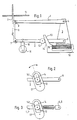
- the saw blade 9 is driven by means of an eccentric 16 via a parallelogram linkage 1, 2, 6.
- the two parallel longitudinal arms 1, 2 are supported at one end in a pivot bearing 4, 5 on a common bearing block 3 and at their other end via a joint 8, 7 with a common connecting link kel 6 connected.
- a quick release bracket for the saw blade 9, not shown in detail, is provided on the connecting leg 6.
- the jigsaw is designed as a stationary device, so that the saw blade 9 protrudes from below through an opening in the workpiece support table 11.
- a motor-driven eccentric 16 is provided, which is connected to the lower longitudinal arm 2 via an eccentric rod 10.
- the saw blade e.g. for industrial fretsaw blades for fine-cut scroll saws
- the connecting leg 6 is designed as a U-shaped bracket, between the legs of which the saw blade 9 is clamped.
- the connecting leg 6 is omitted entirely and the saw blade 9 is clamped directly at the ends of the longitudinal arms 1, 2.
- the longitudinal arms 1, 2 are spread apart, for which purpose, for example, a spindle tensioner can be used which engages and connects ends of the longitudinal arms 1, 2 which are extended beyond the pivot bearings 4, 5.
- the saw blade 9 itself forms the connecting leg of the parallelogram linkage.
- a guide element 12 is provided on the lower longitudinal arm 2, which is designed as a rotatable roller. Alternatively, it can also be designed as a fixed or rotatable pin.
- the circumference of the guide element 12 lies against a flat guide surface 14 of a fixed guide body 13.
- the guide surface 14 is inclined at an acute angle against the connecting leg 6.
- the common bearing block 3, on which the parallelo Gram linkage is mounted is guided displaceably in the horizontal direction. For this purpose, it is penetrated at its lower end by at least one guide rod which is arranged within a fixed U-shaped bracket 18, one leg of which merges into the guide body 13.
- a spring 15 in the form of a pre-compressed helical compression spring is arranged, by means of which the parallelogram linkage with the guide element 12 is pressed against the guide surface 14.
- the parallelogram linkage is moved from its bottom dead center to top dead center (idle stroke)
- the saw blade 9 is moved back by a certain amount, the recess, from the cutting edge.
- the saw blade 9 is again displaced by the same amount, the projection, in parallel in the direction of the cutting edge.
- the size of this projection or recess is predetermined by the positive guidance of the guide element 12 on the inclined guide surface 14.
- the inclination of the guide surface 14 is selected so that the recess which is too large in the case of a fixed, relatively short parallelogram linkage is reduced to a technically ideal dimension of approximately 1 mm.
- the entire parallelogram moves with its pedestal in the direction of the cutting edge, whereby the pressure force of the spring is overcome.
- the guide element 12 designed as a rotatable roller can also be guided on both sides between two parallel guide surfaces 14, 14 'within a recess of a fixed guide bracket 17.
- the guide element 12 lies on both sides with only slight play on the guide surfaces 14, 14 ', so that no spring is required for pressure.
- the angle of the guide bracket 17 is adjustable, so that the size of the projection or recess can be adjusted to a desired dimension.
- a guide element 12 with a guide bracket 17 according to FIG. 2 is provided on each of the two longitudinal arms 1, 2.
- the longitudinal arms 1, 2 can be extended telescopically between their guide brackets 17 and the pivot bearings 4, 5 by means of a bore in which a push rod slides.
- a bearing block provided in the designs according to FIGS. 1 and 2 is therefore not necessary.
Landscapes
- Engineering & Computer Science (AREA)
- Mechanical Engineering (AREA)
- Sawing (AREA)
Applications Claiming Priority (2)
| Application Number | Priority Date | Filing Date | Title |
|---|---|---|---|
| DE3925008A DE3925008A1 (de) | 1989-07-28 | 1989-07-28 | Saege, insbesondere stichsaege oder dekupiersaege |
| DE3925008 | 1989-07-28 |
Publications (1)
| Publication Number | Publication Date |
|---|---|
| EP0410227A1 true EP0410227A1 (de) | 1991-01-30 |
Family
ID=6386038
Family Applications (1)
| Application Number | Title | Priority Date | Filing Date |
|---|---|---|---|
| EP90113398A Withdrawn EP0410227A1 (de) | 1989-07-28 | 1990-07-13 | Säge, insbesondere Stichsäge oder Dekupiersäge |
Country Status (3)
| Country | Link |
|---|---|
| US (1) | US5063807A (https=) |
| EP (1) | EP0410227A1 (https=) |
| DE (1) | DE3925008A1 (https=) |
Families Citing this family (6)
| Publication number | Priority date | Publication date | Assignee | Title |
|---|---|---|---|---|
| US5832611A (en) * | 1996-08-07 | 1998-11-10 | Schmitz; Jeffrey F. | Variable angle reciprocating tool |
| DE10328061A1 (de) * | 2003-06-23 | 2005-01-20 | Robert Bosch Gmbh | Motorgetriebene Stichsägemaschine |
| US8549762B2 (en) * | 2007-02-13 | 2013-10-08 | Robert Bosch Gmbh | Linkage drive mechanism for a reciprocating tool |
| EP2842674A1 (de) * | 2013-08-26 | 2015-03-04 | HILTI Aktiengesellschaft | Hubsägengetriebe |
| EP2842675A1 (de) * | 2013-08-26 | 2015-03-04 | HILTI Aktiengesellschaft | Gegengewichtsvorrichtung |
| CN111098345B (zh) * | 2019-12-31 | 2020-09-11 | 浙江兆和管业有限公司 | 一种pe管材及其加工系统与加工方法 |
Citations (3)
| Publication number | Priority date | Publication date | Assignee | Title |
|---|---|---|---|---|
| DE815839C (de) * | 1950-04-06 | 1951-10-04 | Boehringer G M B H Maschinenfa | Stetig regelbarer Vorschubantrieb fuer Gattersaegen |
| DE2334911C2 (de) * | 1973-02-14 | 1981-12-10 | Helmut 4720 Beckum Abel | Sägeblatteinspannvorrichtung für hin und her gehendeSägen |
| DE3722542A1 (de) * | 1987-07-08 | 1989-01-19 | Reinhard Freund Maschinenfabri | Stichsaege |
Family Cites Families (7)
| Publication number | Priority date | Publication date | Assignee | Title |
|---|---|---|---|---|
| DE343370C (https=) * | ||||
| US1023079A (en) * | 1911-08-07 | 1912-04-09 | Elbridge S Haines | Sawing-machine. |
| US1147063A (en) * | 1914-08-08 | 1915-07-20 | John E Wilson | Saw-guide. |
| DE888046C (de) * | 1943-08-04 | 1953-08-27 | Agfa Ag Fuer Photofabrikation | Verfahren zur Sensibilisierung von Halogensilberemulsionen mit Hilfe von unsymmetrischen Carbocyaninen |
| US4240204A (en) * | 1979-06-19 | 1980-12-23 | Black & Decker Inc. | Jig saw |
| DE3722524A1 (de) * | 1987-06-06 | 1988-12-22 | Krause Johann A Maschf | Fertigungsstrassen sowie verfahren zur fertigung von werkstuecken auf derselben |
| SU1558674A1 (ru) * | 1987-06-23 | 1990-04-23 | Московское Научно-Производственное Объединение По Механизированному Строительному Инструменту И Отделочным Машинам | Механический лобзик |
-
1989
- 1989-07-28 DE DE3925008A patent/DE3925008A1/de active Granted
-
1990
- 1990-07-13 EP EP90113398A patent/EP0410227A1/de not_active Withdrawn
- 1990-07-26 US US07/557,760 patent/US5063807A/en not_active Expired - Fee Related
Patent Citations (3)
| Publication number | Priority date | Publication date | Assignee | Title |
|---|---|---|---|---|
| DE815839C (de) * | 1950-04-06 | 1951-10-04 | Boehringer G M B H Maschinenfa | Stetig regelbarer Vorschubantrieb fuer Gattersaegen |
| DE2334911C2 (de) * | 1973-02-14 | 1981-12-10 | Helmut 4720 Beckum Abel | Sägeblatteinspannvorrichtung für hin und her gehendeSägen |
| DE3722542A1 (de) * | 1987-07-08 | 1989-01-19 | Reinhard Freund Maschinenfabri | Stichsaege |
Also Published As
| Publication number | Publication date |
|---|---|
| DE3925008C2 (https=) | 1992-02-27 |
| DE3925008A1 (de) | 1991-02-07 |
| US5063807A (en) | 1991-11-12 |
Similar Documents
| Publication | Publication Date | Title |
|---|---|---|
| EP0242733B1 (de) | Sägeeinrichtung | |
| EP0736353B1 (de) | Stichsäge | |
| EP1964635B1 (de) | Hubsäge, insbesondere Stichsäge | |
| DE3022493A1 (de) | Motorbetriebene stossaege mit langgestrecktem saegeblatt | |
| EP0163186A2 (de) | Stichsäge zum Bearbeiten von Werkstücken z.B. aus Holz, Kunststoffmaterial oder Metall | |
| WO2005110652A1 (de) | Universalsäge | |
| EP0716897A1 (de) | Pendelhubantrieb für Stichsägen | |
| DE4403186A1 (de) | Handkreissäge mit Pendelschutzhaube und mit einer Gehrungswinkel-Einstellvorrichtung | |
| EP2183072B1 (de) | Handwerkzeugmaschine | |
| EP0340467A2 (de) | Sicherheitseinrichtung an einer Handwerkzeugmaschine | |
| DE3925008C2 (https=) | ||
| EP0215073B1 (de) | Stichsäge | |
| EP1955802B1 (de) | Hubsäge, insbesondere Stichsäge | |
| DE102004045624A1 (de) | Hubsägemaschine | |
| EP1799386B1 (de) | FUßPLATTE FÜR EINE HANDHUBSÄGEMASCHINE | |
| EP1442813B1 (de) | Pendelhubschalter für Stichsägen | |
| DE3540410A1 (de) | Fuer trennarbeiten verwendbare handwerkzeugmaschine wie handkreissaege, trennschleifgeraet od.dgl. | |
| DE3347920A1 (de) | Saegeeinrichtung | |
| WO1999032250A1 (de) | Elektrische handsägemaschine mit wechselbar festlegbarer sägeblattführung | |
| EP0907447A2 (de) | Elektrische handsägemaschine | |
| EP1955803A2 (de) | Hubsäge, insbesondere Stichsäge | |
| DE4033785A1 (de) | Gehrungssaege | |
| DE69403591T2 (de) | Kombinierte Tisch- und Gehrungssäge | |
| DE102008015478A1 (de) | Hand-Werkzeugmaschine mit Befestigungseinrichtung | |
| DE202025002037U1 (de) | Sägevorrichtung |
Legal Events
| Date | Code | Title | Description |
|---|---|---|---|
| PUAI | Public reference made under article 153(3) epc to a published international application that has entered the european phase |
Free format text: ORIGINAL CODE: 0009012 |
|
| AK | Designated contracting states |
Kind code of ref document: A1 Designated state(s): CH DE ES FR GB IT LI NL |
|
| 17P | Request for examination filed |
Effective date: 19901210 |
|
| 17Q | First examination report despatched |
Effective date: 19920907 |
|
| STAA | Information on the status of an ep patent application or granted ep patent |
Free format text: STATUS: THE APPLICATION IS DEEMED TO BE WITHDRAWN |
|
| 18D | Application deemed to be withdrawn |
Effective date: 19930119 |