EP0410074B1 - Dispositif réduisant la charge radiale et palier à friction et compresseur à vis utilisant le dispositif - Google Patents
Dispositif réduisant la charge radiale et palier à friction et compresseur à vis utilisant le dispositif Download PDFInfo
- Publication number
- EP0410074B1 EP0410074B1 EP90103148A EP90103148A EP0410074B1 EP 0410074 B1 EP0410074 B1 EP 0410074B1 EP 90103148 A EP90103148 A EP 90103148A EP 90103148 A EP90103148 A EP 90103148A EP 0410074 B1 EP0410074 B1 EP 0410074B1
- Authority
- EP
- European Patent Office
- Prior art keywords
- radial load
- sliding bearing
- pressure fluid
- fluid chamber
- reducing device
- Prior art date
- Legal status (The legal status is an assumption and is not a legal conclusion. Google has not performed a legal analysis and makes no representation as to the accuracy of the status listed.)
- Expired - Lifetime
Links
- 239000012530 fluid Substances 0.000 claims description 23
- 239000003921 oil Substances 0.000 description 8
- 238000005096 rolling process Methods 0.000 description 5
- 238000007789 sealing Methods 0.000 description 3
- 239000007787 solid Substances 0.000 description 2
- 238000010276 construction Methods 0.000 description 1
- 230000000694 effects Effects 0.000 description 1
- 239000010687 lubricating oil Substances 0.000 description 1
Images
Classifications
-
- F—MECHANICAL ENGINEERING; LIGHTING; HEATING; WEAPONS; BLASTING
- F16—ENGINEERING ELEMENTS AND UNITS; GENERAL MEASURES FOR PRODUCING AND MAINTAINING EFFECTIVE FUNCTIONING OF MACHINES OR INSTALLATIONS; THERMAL INSULATION IN GENERAL
- F16C—SHAFTS; FLEXIBLE SHAFTS; ELEMENTS OR CRANKSHAFT MECHANISMS; ROTARY BODIES OTHER THAN GEARING ELEMENTS; BEARINGS
- F16C32/00—Bearings not otherwise provided for
- F16C32/06—Bearings not otherwise provided for with moving member supported by a fluid cushion formed, at least to a large extent, otherwise than by movement of the shaft, e.g. hydrostatic air-cushion bearings
- F16C32/0629—Bearings not otherwise provided for with moving member supported by a fluid cushion formed, at least to a large extent, otherwise than by movement of the shaft, e.g. hydrostatic air-cushion bearings supported by a liquid cushion, e.g. oil cushion
- F16C32/064—Bearings not otherwise provided for with moving member supported by a fluid cushion formed, at least to a large extent, otherwise than by movement of the shaft, e.g. hydrostatic air-cushion bearings supported by a liquid cushion, e.g. oil cushion the liquid being supplied under pressure
- F16C32/0651—Details of the bearing area per se
- F16C32/0659—Details of the bearing area per se of pockets or grooves
-
- F—MECHANICAL ENGINEERING; LIGHTING; HEATING; WEAPONS; BLASTING
- F04—POSITIVE - DISPLACEMENT MACHINES FOR LIQUIDS; PUMPS FOR LIQUIDS OR ELASTIC FLUIDS
- F04C—ROTARY-PISTON, OR OSCILLATING-PISTON, POSITIVE-DISPLACEMENT MACHINES FOR LIQUIDS; ROTARY-PISTON, OR OSCILLATING-PISTON, POSITIVE-DISPLACEMENT PUMPS
- F04C18/00—Rotary-piston pumps specially adapted for elastic fluids
- F04C18/08—Rotary-piston pumps specially adapted for elastic fluids of intermeshing-engagement type, i.e. with engagement of co-operating members similar to that of toothed gearing
- F04C18/12—Rotary-piston pumps specially adapted for elastic fluids of intermeshing-engagement type, i.e. with engagement of co-operating members similar to that of toothed gearing of other than internal-axis type
- F04C18/14—Rotary-piston pumps specially adapted for elastic fluids of intermeshing-engagement type, i.e. with engagement of co-operating members similar to that of toothed gearing of other than internal-axis type with toothed rotary pistons
- F04C18/16—Rotary-piston pumps specially adapted for elastic fluids of intermeshing-engagement type, i.e. with engagement of co-operating members similar to that of toothed gearing of other than internal-axis type with toothed rotary pistons with helical teeth, e.g. chevron-shaped, screw type
-
- F—MECHANICAL ENGINEERING; LIGHTING; HEATING; WEAPONS; BLASTING
- F01—MACHINES OR ENGINES IN GENERAL; ENGINE PLANTS IN GENERAL; STEAM ENGINES
- F01C—ROTARY-PISTON OR OSCILLATING-PISTON MACHINES OR ENGINES
- F01C21/00—Component parts, details or accessories not provided for in groups F01C1/00 - F01C20/00
- F01C21/02—Arrangements of bearings
-
- F—MECHANICAL ENGINEERING; LIGHTING; HEATING; WEAPONS; BLASTING
- F04—POSITIVE - DISPLACEMENT MACHINES FOR LIQUIDS; PUMPS FOR LIQUIDS OR ELASTIC FLUIDS
- F04C—ROTARY-PISTON, OR OSCILLATING-PISTON, POSITIVE-DISPLACEMENT MACHINES FOR LIQUIDS; ROTARY-PISTON, OR OSCILLATING-PISTON, POSITIVE-DISPLACEMENT PUMPS
- F04C29/00—Component parts, details or accessories of pumps or pumping installations, not provided for in groups F04C18/00 - F04C28/00
- F04C29/0021—Systems for the equilibration of forces acting on the pump
-
- F—MECHANICAL ENGINEERING; LIGHTING; HEATING; WEAPONS; BLASTING
- F16—ENGINEERING ELEMENTS AND UNITS; GENERAL MEASURES FOR PRODUCING AND MAINTAINING EFFECTIVE FUNCTIONING OF MACHINES OR INSTALLATIONS; THERMAL INSULATION IN GENERAL
- F16C—SHAFTS; FLEXIBLE SHAFTS; ELEMENTS OR CRANKSHAFT MECHANISMS; ROTARY BODIES OTHER THAN GEARING ELEMENTS; BEARINGS
- F16C39/00—Relieving load on bearings
- F16C39/04—Relieving load on bearings using hydraulic or pneumatic means
-
- F—MECHANICAL ENGINEERING; LIGHTING; HEATING; WEAPONS; BLASTING
- F16—ENGINEERING ELEMENTS AND UNITS; GENERAL MEASURES FOR PRODUCING AND MAINTAINING EFFECTIVE FUNCTIONING OF MACHINES OR INSTALLATIONS; THERMAL INSULATION IN GENERAL
- F16C—SHAFTS; FLEXIBLE SHAFTS; ELEMENTS OR CRANKSHAFT MECHANISMS; ROTARY BODIES OTHER THAN GEARING ELEMENTS; BEARINGS
- F16C2360/00—Engines or pumps
- F16C2360/43—Screw compressors
Definitions
- the present invention relates to a radial load reducing device according to the preamble of claim 1, and also relates to a sliding bearing and a screw compressor using the above device.
- EP-A-0 112 011 there is disclosed a radial load reducing device to be used in a bearing for gear pumps.
- an oil groove or a second recess is located opposite to a high pressure fluid chamber or a first recess which lies within a critical zone of load concentration within a bearing bush.
- the second recess lies wholly outside the critical zone and provides a reservoir of fluid which reduces cavitations resulting from low pressures arising from radial movements of a shaft within the bush.
- the oil groove faces a second outer circumferential portion of the rotating body
- the device further comprises a low-pressure fluid chamber defined to face substantially the first circumferential portion of the rotating body at the second position opposite to the first position, and a part of the low-pressure fluid chamber faces a third circumferential portion of the rotating body located between the first and the second circumferential portion. Therefore, the upper limit of the radial load to be applied by the sliding bearing in which this device is used, can be increased and the life of the bearing can be extended if the radial load is fixed, respectively.
- the object is further achieved by a sliding bearing and a screw compressor using the above described radial load reducing device
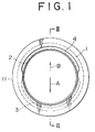
- a radial load is applied to the rotating shaft 2 in a direction depicted by a solid arrow A.
- a high-pressure fluid chamber 3 is defined to face a first outer circumferential portion of the rotating shaft 2 at a first position directed by the arrow A
- a low-pressure fluid chamber 4 is defined to face the same first outer circumferential portion of the rotating shaft 2 at a second position reversely directed by the arrow A.
- Reducing device 1 is formed by the high-pressure fluid chamber 3, a low-pressure fluid chamber 4 and an oil groove 13 for storing a lubricating oil, which is formed on the opposite side of the low-pressure fluid chamber 4 with respect to a wall portion 12.
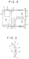
- the low-pressure fluid chamber 4 is provided with a part forming an extending portion 14 for allowing the oil in the oil groove 13 and the high-pressure fluid chamber 3 to flow as shown by arrows C in Fig. 2.
- a gap between the rotating shaft 2 and a boundary portion 15 between the high-pressure fluid chamber 3 and the low-pressure fluid chamber 4 should be greater than a gap between the rotating shaft 2 and an inner circumferential portion 16 of the extending portion 14 on the oil groove 13 side, so as to avoid the load from being applied to the boundary portion 15.
- the opposite ends of the gap as shown by circles D of dashed lines in Fig. 3 should be formed into a wedge shape so as to generate a hydraulic pressure.
- the high-pressure fluid chamber 3 is filled with a pressure fluid such as oil or air having a suitable pressure
- the low-pressure fluid chamber 4 is filled with a pressure fluid having a pressure lower than that in the high-pressure fluid chamber 3, so that a force may be applied to the rotating shaft 2 in a direction as depicted by a dotted arrow B counter to the solid arrow A.
- a force may be applied to the rotating shaft 2 in a direction as depicted by a dotted arrow B counter to the solid arrow A.
- the radial load to be applied to the rotating shaft 2 can be reduced by the device 1.
- a radial bearing is classified into a rolling bearing and a sliding bearing.
- the rolling bearing is used in case of a relatively low load, while the sliding bearing is used in case of a high load where the rolling bearing cannot be used.
- An energy loss of the sliding bearing is greater than that of the rolling bearing.
- the rolling bearing and the sliding bearing can endure a higher load as compared with the case that the device 1 is not applied. Further, if the load is fixed, a longer life of the radial bearing can be expected.
- the device 1 may be provided at a suitable position in the axial direction of the rotating shaft 2, that is, the position is not limited.
- the device 1 may be provided at a shaft sealing portion of the rotating shaft 2. In this case, as a hydraulic pressure is applied to the shaft sealing portion to be sealed, a shaft sealing effect can also be improved.
- a screw compressor may be formed by using the device 1. Accordingly, the compressor may be operated under a higher pressure owing to the extension of the life of the bearing and the expansion of the applicable load range.
Claims (3)
- Dispositif de réduction de charge radiale (1), comprenant :- une chambre à fluide à haute pression (3), définie pour être en regard d'une première partie circonférentielle extérieure d'un corps tournant (2), en une première position, en vue de l'application d'une charge radiale audit corps tournant;- une gorge à huile (13), destinée à stocker un fluide, définie pour être en regard dudit corps tournant (2), en une seconde position opposée à ladite première position,
caractérisé en ce que- ladite gorge à huile (13) est en regard d'une seconde partie circonférentielle dudit corps tournant (2), et- ledit dispositif de réduction de charge radiale (1) comprend en outre une chambre à fluide à basse pression (4), définie pour être en regard pratiquement de ladite première partie circonférentielle dudit corps tournant (2), en ladite seconde position opposée à ladite première position, dans lequel- une partie (14) de ladite chambre à basse pression (4) est en regard d'une troisième partie circonférentielle dudit corps tournant (2), située entre lesdites première et seconde partie circonférentielles. - Palier à glissement (11) utilisant un dispositif de réduction de charge radiale (1) selon la revendication 1.
- Compresseur à vis utilisant un dispositif de réduction de charge radiale (1) selon la revendication 1.
Applications Claiming Priority (2)
| Application Number | Priority Date | Filing Date | Title |
|---|---|---|---|
| JP1197492A JPH0361714A (ja) | 1989-07-28 | 1989-07-28 | ラジアル荷重軽減装置およびこれを用いた滑り軸受およびスクリュ圧縮機 |
| JP197492/89 | 1989-07-28 |
Publications (3)
| Publication Number | Publication Date |
|---|---|
| EP0410074A2 EP0410074A2 (fr) | 1991-01-30 |
| EP0410074A3 EP0410074A3 (en) | 1991-10-09 |
| EP0410074B1 true EP0410074B1 (fr) | 1993-12-15 |
Family
ID=16375371
Family Applications (1)
| Application Number | Title | Priority Date | Filing Date |
|---|---|---|---|
| EP90103148A Expired - Lifetime EP0410074B1 (fr) | 1989-07-28 | 1990-02-19 | Dispositif réduisant la charge radiale et palier à friction et compresseur à vis utilisant le dispositif |
Country Status (5)
| Country | Link |
|---|---|
| US (1) | US4989997A (fr) |
| EP (1) | EP0410074B1 (fr) |
| JP (1) | JPH0361714A (fr) |
| KR (1) | KR940001627B1 (fr) |
| DE (1) | DE69005217T2 (fr) |
Families Citing this family (12)
| Publication number | Priority date | Publication date | Assignee | Title |
|---|---|---|---|---|
| US5503478A (en) * | 1995-04-03 | 1996-04-02 | Federal-Mogul Corporation | Lubricant distribution system for bearings and bushings |
| US6000920A (en) * | 1997-08-08 | 1999-12-14 | Kabushiki Kaisha Kobe Seiko Sho | Oil-flooded screw compressor with screw rotors having contact profiles in the shape of roulettes |
| US6241392B1 (en) * | 2000-01-21 | 2001-06-05 | Coltec Industries Inc | Hybrid bearing |
| US6579076B2 (en) * | 2001-01-23 | 2003-06-17 | Bristol Compressors, Inc. | Shaft load balancing system |
| BE1014043A3 (nl) * | 2001-03-07 | 2003-03-04 | Atlas Copco Airpower Nv | Watergeinjecteerd schroefcompressorelement. |
| US7559696B2 (en) * | 2004-08-30 | 2009-07-14 | Hamilton Sundstrand Corporation | Active thrust management system |
| JP4387402B2 (ja) | 2006-12-22 | 2009-12-16 | 株式会社神戸製鋼所 | 軸受及び液冷式スクリュ圧縮機 |
| ITTO20110912A1 (it) * | 2011-10-13 | 2013-04-14 | Vhit Spa | Pompa per vuoto rotativa |
| US9284976B2 (en) | 2013-03-09 | 2016-03-15 | Waukesha Bearings Corporation | Countershaft |
| US9279446B2 (en) * | 2013-03-09 | 2016-03-08 | Waukesha Bearings Corporation | Bearing with axial variation |
| JP6209477B2 (ja) * | 2014-03-28 | 2017-10-04 | 株式会社神戸製鋼所 | 圧縮機 |
| JP6790574B2 (ja) * | 2016-08-12 | 2020-11-25 | 株式会社ジェイテクト | 主軸装置と、該主軸装置を備えた研削盤 |
Family Cites Families (8)
| Publication number | Priority date | Publication date | Assignee | Title |
|---|---|---|---|---|
| DE1575533A1 (de) * | 1966-07-19 | 1971-06-09 | Lucas Industries Ltd | Lager |
| US3909081A (en) * | 1974-03-26 | 1975-09-30 | Mechanical Tech Inc | Load balancing system for rotating shafts |
| SE422348B (sv) * | 1977-10-24 | 1982-03-01 | Stal Refrigeration Ab | Anordning vid en kompressor av rotationstyp for att fixera en rotoraxel i axiell led |
| CA1096431A (fr) * | 1978-07-03 | 1981-02-24 | Kunio Shibata | Coussinet hydraulique |
| US4310203A (en) * | 1978-10-25 | 1982-01-12 | Karl Eickmann | Hydrostatic support assembly |
| EP0112011B1 (fr) * | 1982-11-10 | 1987-09-16 | LUCAS INDUSTRIES public limited company | Palier pour pompe à engrenages |
| JP2616922B2 (ja) * | 1987-05-22 | 1997-06-04 | 株式会社日立製作所 | スクリユー圧縮機 |
| GB8723129D0 (en) * | 1987-10-02 | 1987-11-04 | Lucas Ind Plc | Bearings for gear pumps |
-
1989
- 1989-07-28 JP JP1197492A patent/JPH0361714A/ja active Pending
-
1990
- 1990-02-01 US US07/473,407 patent/US4989997A/en not_active Expired - Fee Related
- 1990-02-19 DE DE90103148T patent/DE69005217T2/de not_active Expired - Fee Related
- 1990-02-19 EP EP90103148A patent/EP0410074B1/fr not_active Expired - Lifetime
- 1990-03-03 KR KR1019900002776A patent/KR940001627B1/ko not_active IP Right Cessation
Also Published As
| Publication number | Publication date |
|---|---|
| JPH0361714A (ja) | 1991-03-18 |
| DE69005217D1 (de) | 1994-01-27 |
| KR940001627B1 (ko) | 1994-02-28 |
| DE69005217T2 (de) | 1994-04-28 |
| KR910003262A (ko) | 1991-02-27 |
| US4989997A (en) | 1991-02-05 |
| EP0410074A3 (en) | 1991-10-09 |
| EP0410074A2 (fr) | 1991-01-30 |
Similar Documents
| Publication | Publication Date | Title |
|---|---|---|
| EP0410074B1 (fr) | Dispositif réduisant la charge radiale et palier à friction et compresseur à vis utilisant le dispositif | |
| EP0470409B1 (fr) | Garniture mécanique d'étanchéité sans contact | |
| US4553761A (en) | Seal | |
| KR100294175B1 (ko) | 비선회스크롤부재와선회스크롤부재사이의분리력을감소시킨스크롤압축기 | |
| EP0466076A2 (fr) | Garniture à bague glissante avec rainures hélicoidales | |
| EP1437536B1 (fr) | Bague anti-extrusion pour joint élastomère ainsi que bride | |
| US20010045703A1 (en) | Piston sealing ring assembly | |
| KR100417478B1 (ko) | 회전 샤프트 시일 | |
| US5222879A (en) | Contact-less seal and method for making same | |
| US5066027A (en) | Sealing ring apparatus | |
| EP0424372B1 (fr) | Joint d'etancheite combine servant a assurer l'etancheite entre deux pieces mecaniques | |
| WO1990010808A1 (fr) | Joint d'etancheite pour un verin hydraulique | |
| US5725221A (en) | Two piece seal | |
| KR100315871B1 (ko) | 스크루압축기 | |
| US6428010B1 (en) | Sealing strip | |
| JP2000081146A (ja) | 密封装置 | |
| CN100443724C (zh) | 泵 | |
| JP3059230B2 (ja) | ラジアル・ピストンポンプ | |
| US4043255A (en) | Cam follower piston | |
| JPH0517993B2 (fr) | ||
| JP4106022B2 (ja) | ボール弁 | |
| US5716142A (en) | Radial journal bearing with slide shoe | |
| GB2113308A (en) | Rotary positive-displacement fluid-machine | |
| JPS628417Y2 (fr) | ||
| US20040195780A1 (en) | Back pumping seal assembly |
Legal Events
| Date | Code | Title | Description |
|---|---|---|---|
| PUAI | Public reference made under article 153(3) epc to a published international application that has entered the european phase |
Free format text: ORIGINAL CODE: 0009012 |
|
| 17P | Request for examination filed |
Effective date: 19900219 |
|
| AK | Designated contracting states |
Kind code of ref document: A2 Designated state(s): BE DE GB SE |
|
| PUAL | Search report despatched |
Free format text: ORIGINAL CODE: 0009013 |
|
| AK | Designated contracting states |
Kind code of ref document: A3 Designated state(s): BE DE GB SE |
|
| 17Q | First examination report despatched |
Effective date: 19920213 |
|
| GRAA | (expected) grant |
Free format text: ORIGINAL CODE: 0009210 |
|
| AK | Designated contracting states |
Kind code of ref document: B1 Designated state(s): BE DE GB SE |
|
| REF | Corresponds to: |
Ref document number: 69005217 Country of ref document: DE Date of ref document: 19940127 |
|
| PLBE | No opposition filed within time limit |
Free format text: ORIGINAL CODE: 0009261 |
|
| STAA | Information on the status of an ep patent application or granted ep patent |
Free format text: STATUS: NO OPPOSITION FILED WITHIN TIME LIMIT |
|
| 26N | No opposition filed | ||
| EAL | Se: european patent in force in sweden |
Ref document number: 90103148.4 |
|
| PGFP | Annual fee paid to national office [announced via postgrant information from national office to epo] |
Ref country code: GB Payment date: 19960212 Year of fee payment: 7 |
|
| PGFP | Annual fee paid to national office [announced via postgrant information from national office to epo] |
Ref country code: SE Payment date: 19960215 Year of fee payment: 7 |
|
| PGFP | Annual fee paid to national office [announced via postgrant information from national office to epo] |
Ref country code: DE Payment date: 19960227 Year of fee payment: 7 |
|
| PGFP | Annual fee paid to national office [announced via postgrant information from national office to epo] |
Ref country code: BE Payment date: 19960412 Year of fee payment: 7 |
|
| PG25 | Lapsed in a contracting state [announced via postgrant information from national office to epo] |
Ref country code: GB Effective date: 19970219 |
|
| PG25 | Lapsed in a contracting state [announced via postgrant information from national office to epo] |
Ref country code: SE Effective date: 19970220 |
|
| PG25 | Lapsed in a contracting state [announced via postgrant information from national office to epo] |
Ref country code: BE Effective date: 19970228 |
|
| BERE | Be: lapsed |
Owner name: KOBE SEIKO SHO ALSO KNOWN AS KOBE STEEL LTD K.K. Effective date: 19970228 |
|
| GBPC | Gb: european patent ceased through non-payment of renewal fee |
Effective date: 19970219 |
|
| PG25 | Lapsed in a contracting state [announced via postgrant information from national office to epo] |
Ref country code: DE Effective date: 19971101 |
|
| EUG | Se: european patent has lapsed |
Ref document number: 90103148.4 |