EP0409891B1 - System zur messung der abmessungen eines werkstückes - Google Patents
System zur messung der abmessungen eines werkstückes Download PDFInfo
- Publication number
- EP0409891B1 EP0409891B1 EP89904948A EP89904948A EP0409891B1 EP 0409891 B1 EP0409891 B1 EP 0409891B1 EP 89904948 A EP89904948 A EP 89904948A EP 89904948 A EP89904948 A EP 89904948A EP 0409891 B1 EP0409891 B1 EP 0409891B1
- Authority
- EP
- European Patent Office
- Prior art keywords
- workpiece
- receivers
- receiver
- output
- energy
- Prior art date
- Legal status (The legal status is an assumption and is not a legal conclusion. Google has not performed a legal analysis and makes no representation as to the accuracy of the status listed.)
- Expired
Links
- 238000003491 array Methods 0.000 claims abstract description 7
- 239000000463 material Substances 0.000 abstract description 39
- 238000012937 correction Methods 0.000 abstract description 7
- 238000005259 measurement Methods 0.000 description 10
- 238000010586 diagram Methods 0.000 description 7
- 230000006870 function Effects 0.000 description 5
- 230000000630 rising effect Effects 0.000 description 4
- 230000007423 decrease Effects 0.000 description 2
- 238000001514 detection method Methods 0.000 description 2
- 230000003287 optical effect Effects 0.000 description 2
- 230000004044 response Effects 0.000 description 2
- 239000000126 substance Substances 0.000 description 2
- 238000012360 testing method Methods 0.000 description 2
- 241001590997 Moolgarda engeli Species 0.000 description 1
- 230000000903 blocking effect Effects 0.000 description 1
- 239000003990 capacitor Substances 0.000 description 1
- 239000000919 ceramic Substances 0.000 description 1
- 230000001934 delay Effects 0.000 description 1
- 239000012530 fluid Substances 0.000 description 1
- 238000003384 imaging method Methods 0.000 description 1
- 238000012545 processing Methods 0.000 description 1
- 239000000523 sample Substances 0.000 description 1
- 230000035945 sensitivity Effects 0.000 description 1
- 230000007704 transition Effects 0.000 description 1
- 230000001960 triggered effect Effects 0.000 description 1
- 238000011144 upstream manufacturing Methods 0.000 description 1
Images

Classifications
-
- G—PHYSICS
- G01—MEASURING; TESTING
- G01B—MEASURING LENGTH, THICKNESS OR SIMILAR LINEAR DIMENSIONS; MEASURING ANGLES; MEASURING AREAS; MEASURING IRREGULARITIES OF SURFACES OR CONTOURS
- G01B17/00—Measuring arrangements characterised by the use of infrasonic, sonic or ultrasonic vibrations
Definitions
- the present invention relates to a system which utilizes transmitted energy, such as ultrasonic energy, to measure one or more dimensions of a workpiece, such as sheet arterial.
- transmitted energy such as ultrasonic energy
- processors for developing exposed X-ray film have been known to use an optical scanner system to determine the length and width of the film before it is transported through the processor. Typically, this size information is used to adjust the input of fresh chemicals into the processor, as well as to sort the exposed film according to size.
- One processor is known to use an array of infrared transmitting diodes to scan the film. Located opposite from the transmitting diodes are a lesser number of infrared detecting diodes. When the film is transmitted between the transmitting and detecting arrays, some of the infrared light is blocked from reaching the detector diodes. This information can be used to adjust the replenishment rate of chemicals into the processor.
- a problem in using an infrared measurement system is that some of the newer X-ray films exhibit sensitivity in the infrared region. Thus when these films are exposed to infrared energy, the film becomes "fogged" thereby obscuring the developed image.
- Kanda et al in U.S. 4,511,998, discloses an acoustic imaging instrument which includes opposing arrays of acoustic transducer elements and acoustic detecting elements.
- an acoustic system for detecting the presence or absence of paper includes a receiver which detects a change in the acoustic impedance of a receiving port when the paper is absent of in close proximity to the port.
- Miyamoto in U.S. 4,620,781 discloses an image processing system which includes a photosensor for detecting the size of an original document.
- an optical scanner for the scanning of documents and to determine the condition of a document and especially to determine the position of the edges of the document and the position of holes or tears in the document.
- This apparatus uses linear arrays of light emitters and receivers using light of short wavelengths, and deriving signals indicative of the relative intensity value of each analogue light receiver with regard to three or more predetermined threshold values of intensity, each threshold level corresponding to a different degree of obscuration of a sensor by the corresponding area of the document.
- the apparatus also utilizes automatic gain control by using one amplifier of variable gain for each of the light receivers whereby the gain of the amplifier is set to give a full scale output when no document is in the path.
- GB 2 048 482 discloses an ultrasonic testing method for recognizing boundaries or contours of a workpiece, using a plurality of ultrasonic probe units which are arranged in one or more rows and coupled acoustically to the test piece by means of fluid.
- the present invention pertains to an apparatus for determining the dimensions of a flat workpiece as defined by the claims.
- the apparatus includes energy measuring means having i) a plurality of transmitters of energy, and ii) a plurality of receivers of that energy.
- the transmitters are separated from the receivers in order to pass the workpiece between them in a manner that the energy to at least one of the receivers is obstructed by the workpiece.
- Each of the receivers generates an output which is a function of the energy received from the transmitters.
- the present invention also includes means, responsive to the output, for determining the dimension of the workpiece as a function of the number of receivers which receive energy from the transmitters.
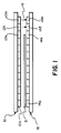
- Fig. 1 a row of ultrasonic transmitting transducers which are spaced apart from a row of receiving transducers.
- a workpiece such as a piece of sheet material
- the signals to some of the receiving transducers are blocked.
- the number of transducers receiving these transmitted signals is compared to the number not receiving the transmitted signals, and these values are used to calculate a sheet width value.
- the length of each sheet is determined by measuring the time differential between the first interruption of the transmitted signals and the last interruption, and by multiplying this time differential by the known transit speed of the sheet material.
- Figs. 1 and 2 where there is shown a linear array indicated at 10 of ultrasonic transmitting transducers 12a through 12m which are driven by an oscillator/driver 13, and which are spaced apart from a like number of receiving transducers 14a through 14m which are part of a linear array indicated at 16.
- the transducers 12a through 12m are positioned in a linear side-by-aide manner, as are the transducers 14a through 14m.
- the transducers are ceramic transducers, model EFR-RSB-40K manufactured by Panasonic; the transmitting transducers being spaced apart from the receiving transducers across a gap 15 a distance of approximately 12.5 mm (0.5 inch).
- sheet material S having a width dimension w is transported by a conveyor (not shown) between the arrays 10, 16 and in a direction which is perpendicular to the plane of Fig. 1.
- Fig. 1 it can be seen that the signals from transmitting transducers 12a through 12k are blocked by the sheet material S from reaching the receiving transducers, while the signals to transducers 141 and 14m remain unblocked.
- the width of the sheet material can be determined in a conventional manner.
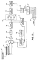
- a conventional time multiplexer 18 (Fig. 2) is provided. Multiplexer 18 reads the receiving transducer outputs sequentially, from 14a through 14m, in two millisecond intervals, and feeds these signals to a downstream amplifier 20.
- the multiplexer 18 is addressed by a MUX address generator 24 which in turn is clocked by a conventional clock generator 26.
- the address generator 24 is a five bit counter and the clock generator is a phase locked loop IC operating at 500 Hz.
- the amplifier 20 in providing about 55 dB of gain, increases the noise level resulting from multiplexer switching transients.
- the amplified output is fed through a gate 28 which is open only during the middle one millisecond of each receiver output. In this manner, a majority of the noise which is present at the beginning and end of each receiver output is gated out.
- This allows about forty cycles of the receiving transducer signal to be fed downstream to a peak detector 30 which generates an output which is equal to the peak value of each signal.
- the output of the peak detector is a signal of slightly less than one millisecond duration; this signal having an amplitude which is proportional to the output of the addressed receiving transducer.
- each receiver signal is thresholded to three levels set at a thresholding circuit 32 (Fig. 2). That is, as the sheet material begins to pass between a transmitter and receiver pair, the percentage of the signal reaching the receiver decreases.
- this decrease in the signal strength is directly proportional to the extent that the receiving transducer is blocked by the sheet material.
- this proportionally is used to determine the position of the sheet material between adjacent receiving transducers in order to provide a more accurate measurement of sheet material width.
- the thresholding circuit 32 includes three comparators 33 (Fig. 2) which are utilized to establish three threshold levels.
- the amplifier gain is set so that when the sheet material is absent from the transducer gap, the resulting maximum voltage is equal to ten volts.
- the comparators are set to switch at 2.5V, 5.0V, and 7.5V. These levels correspond to the transducer being 75%, 50% and 25% blocked, respectively, by the sheet material. In this example there is a twenty dB difference between the voltage output when the transducer is fully blocked and totally unblocked, with the fully blocked voltage being around one volt.
- the combined outputs of the comparators In order to privde an output indicative of the threshold level, the combined outputs of the comparators generate a three bit binary code which represents the signal level at the thresholder for each receiver output. In this manner, a threshold output of 111 corresponds to a completely unblocked receiver, while an output of 000 corresponds to a completely blocked receiver.
- the percentage of the transducer that is blocked by the sheet material As well as the diameter of the transducer, the location of the edge of the sheet material with respect to the transducer can be more accurately calculated.
- the percentage of obstruction as a function of the output codes is set forth in further detail in Table 1 below.
- the three bit threshold code (bits A, B, C) is fed downstream to a shift register 34 in a manner that the number of logic high bits of the code generates a corresponding number of low-to-high transitions out of the shift register which are then used to clock a downstream down counter 36.
- the resulting counter output is held in a downstream latch 38 and the counter 36 is reset. This reset occurs in response to a carryout pulse which is generated from the multiplexer address generator 24 after all of the receivers have been read.
- the latched value is a seven bit number which represents the width of the sheet material. This binary number is converted in a conventional manner into an arithmetic quantity at a downstream location.
- an octal inverting buffer 37 is tied to the output of latch 38.
- the output of the buffer 37 is fed to a multiple input NAND gate 39.
- any of the bits from latch 38 go high indicating the presence of sheet material in the gap, at least one of the outputs from the buffer 37 goes low. This generates a logic high out of the gate 39 which remains high as long as sheet material is present in the gap.
- the length of the sheet material is calculated in a conventional manner at a downstream location.
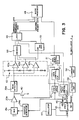
- incoming signals from the receiving transducers are selected in a sequential manner by the multiplexer 18a and boosted by a number of downstream amplifiers identified by the number 20a.
- the center portion of each receiver signal is gated by a transistor 40 which has its base tied to the output of a gate controller 42.
- Clocking pulses to the gate controller 42 are generated by a 1.12 MHz oscillator 44 whose output is divided down by a frequency divider 45 into a number of different clock frequencies. For example, a 546 Hz output is generated at an output 46 for clocking the MUX address generator 24a as well as for triggering a one shot multivibrator 47. In addition, a 4.37 Khz signal is generated at an output 48 of the frequency divider for clocking a output latch controller 50, as well as for clocking a data ready latch controller 51, and the gate controller 42. Furthermore, a 35 Kh signal is generated at an output 52 of the frequency divider for driving the transmitting transducer oscillator 13 (Fig. 1) via a voltage amp 54 and current amp 56.
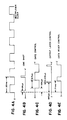
- Fig. 4 the timing diagram of Fig. 4 which is not drawn to scale.
- the rising edges of the aforementioned 546 Hz clock signal shown in line “a" of Fig. 4 trigger the one shot multivibrator 47 (Fig. 3) to generate the signal shown in line “b” of Fig. 4.
- the one shot simultaneously pulses the gate control 42, the output latch control 50 and the data ready control 51 so that the parallel data at their inputs is read in; this data being clocked out serially when the one shot pulse terminates.
- the gate control 42 is a shift register having eight parallel inputs which are hardwired to clock out the bit pattern 11000011 at a 4.37 Khz rate is order to generate the pulse train which is shown at line "c" of Fig. 4.
- the gating signal When the gating signal is low, it turns off the gating transistor 40 (Fig. 3) which permits the middle portion of the signal to be fed to the peak detecter 30a.
- the gate (line c) is open only during the middle portion of each multiplexer clock cycle (line a). In this manner, the gating function is achieved by permitting only the middle portion of each cycle from the multiplexer 18a to proceed downstream to the peak detector 30a from where it is fed to the thresholding circuit.
- the thresholding circuit includes three comparators 60a, 60b, and 60c (Fig. 3), each of which has one input tied to the output of the peak detector 30a.
- the remaining inputs of these comparators are tied to a voltage divider indicated at 62 which sets the switching levels of the comparators so that comparator 60c switches at 1/4 the supply voltage level (+V), comparator 60b switches at 1/2 of +V, and comparator 60a switches at 3/4 of +V.
- comparator 60c switches at 1/4 the supply voltage level (+V)
- comparator 60b switches at 1/2 of +V
- comparator 60a switches at 3/4 of +V.
- the output latch control 50 (Fig. 3) includes a conventional shift register which is enabled by the one shot multivibrator 47, and which is clocked by the 4.37 kHz clock.
- the signal output from latch 50 (shown in line “d” of Fig. 4) is generated by hardwiring the eight parallel inputs of the shift register to generate the following serial output: 00001000.
- the rising edge of the output latch control pulse occurs during the latter half of the gating pulse shown in line "c", in order to latch the output of encoder 64.
- the data ready control 51 includes a shift register which has eight hardwired parallel inputs to generate the following binary output: 00000111. Since the shift register is also clocked at a 4.37 kHz rate, and since it is enabled by the rising edge of the one shot pulse, the data ready control pulse occurs just after the termination of the latch control pulse as shown in line "e" of Fig. 4.
- the length dimension of the sheet material is determined by a signal to the microprocessor 68 (Fig. 3) which indicates when the sheet material is present in the gap between the transmitting and receiving transducers.
- This signal is generated by utilizing a retriggerable one shot multivibrator 70 which is enabled by the output of the middle threshold comparator 60b whenever there is sheet material present.
- the one shot 70 is triggered and retriggered by the signal from the output latch controller 50 so that a "material present" signal is generated as long as sheet material is in the gap. This signal is held at the latch 66 where it is retrieved by the microprocessor 68.
- the measurement system includes an automatic calibration circuit 41 (Fig. 2) which is provided to correct for variations in the operation of the individual transmitting and receiving transducers 16. More specifically, the calibration circuit 41 normalizes the variations is signal strength out of the receiver transducers which are primarily due to variations between the drive frequency, transmitting transducer frequency, and receiving transducer frequency. These variations can affect the measurement accuracy of the system.
- an automatic calibration circuit 41 Fig. 2 which is provided to correct for variations in the operation of the individual transmitting and receiving transducers 16. More specifically, the calibration circuit 41 normalizes the variations is signal strength out of the receiver transducers which are primarily due to variations between the drive frequency, transmitting transducer frequency, and receiving transducer frequency. These variations can affect the measurement accuracy of the system.
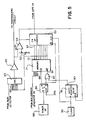
- Fig. 5 where there is shown a multiplying digital-to-analog converter 43 followed by an amplifier 49.
- the purposes of the DAC 43 and amplifier 49 are to act together as a variable gain unit to compensate for the aforementioned variations between transducers.
- the amount of compensation per receiver is determined in a powerup calibration sequence when sheet material is absent from the gap. That is, during this time a calculation is made of the amount by which each receiver output varies from a reference level; this amount constituting a correction value for each receiver output. Then when the sheet material is present in the gap, and the various receiver outputs are sequentially accessed by the multiplexer 18 (Fig. 2), the corresponding correction value adjusts the output from the accessed receiver.
- the correction values for each receiver are determined in the power-up calibration mode by means of an up counter 53 which counts up from zero to the reference value.
- the up counter 53 is enabled by a comparator 59 which has one input 61 tied to the output of the amplifier 49, and which has its other input tied to a voltage divider 63 which sets the switching level of the comparator 59.
- the counter 53 is enabled and it counts up linearly as shown by line “c" in Fig. 6.
- the up counter 53 is disabled by the comparator output (line “d” of Fig. 6), and the counter output is fed into a memory 71 whose input/outputs 72 are tied to the outputs 57 of the counter. In this manner, memory 71 contains the correction offsets for each receiver output at addresses which correspond to the proper receiver outputs.
- the switching output from the comparator 59 which disables the counter 53, also is fed to the parallel/serial input of a shift register delay circuit 78 which jams into the register eight hardwired parallel inputs with the bit pattern 11101111.
- the shift register returns to its serial mode, it serially clocks out this bit pattern shown at line "e" of Fig. 6.
- the inverting output 80 is tied to the input of an OR gate 82, whose other input is tied to the Q NOT output of an upstream flip flop 84; the output of gate 82 being tied to the write enable input 86 of the memory 71.
- the "0" bit from the shift register 78 delays the writing of the count from counter 53 into memory 71 for three clockings until the counter output has settled. Chocking of the shift register delay circuit 78 is accomplished by a 250 kHz output from a conventional clock 90. This output is also used to clock the up counter 53. In order to prepare for another countup is response to the next receiving transducer output, the counter 58 is reset to zero by the next rising edge output from gate 28.
- a power up signal to the D input of the flip flop 84 (Fig. 5) is generated by a conventional resistor-capacitor circuit 88 which outputs a logic high during initial power up of the system so that i) Q NOT is low thereby enabling the write enable of memory 71 (when the signal out of the shift register delay 80 is also low), and ii) Q is high, thereby disabling output enable 89 of the memory 71.
- the calibration mode is terminated and an operational mode begins when the RC network of the power up circuit charges up thereby causing the Q NOT output of flip flop 84 to go high. This disables the write enable of memory 71 and tristates the outputs 57 of the counter 53. At the same time, the Q output of flip flop 84 goes low thereby enabling the outputs 72 of the memory 71.
- the Q and Q NOT outputs from flip flop 84 are clocked out by the end of the line (EOL) pulse from the MUX address generator 24.
- the EOL pulse is active after all of the receiving transducers have been addressed by the multiplexer address generator 24 (Fig. 2).
- the correction offset for the current address from the MUX address generator 24 is output from memory 71. From there it is sent to the multiplying DAC 43 where it adjusts the level of the signal from the peak detector to correct the variance for that receiver output in the manner discussed previously.
Landscapes
- Physics & Mathematics (AREA)
- General Physics & Mathematics (AREA)
- Length Measuring Devices Characterised By Use Of Acoustic Means (AREA)
- Measurement Of Velocity Or Position Using Acoustic Or Ultrasonic Waves (AREA)
- Controlling Sheets Or Webs (AREA)
Claims (4)
die Geberelemente (12a-12m) und die Empfängerelemente (14a-14m) aus Ultraschallwandlern bestehen,
eine Einrichtung (62) vorgesehen ist, die einen ersten, zweiten und dritten Schwellenwert festlegt, der 75 % bzw. 50% bzw. 25% der Blockierung eines einzelnen Empfängerelements durch das Werkstück entspricht,
Vergleichsmittel (60a, 60b, 60c) vorgesehen sind, die die Menge der abgegebenen und von jedem Empfängerelement empfangenen Energie mit dem ersten, zweiten und dritten Schwellenwert vergleichen und ein erstes, zweites und drittes Signal erzeugen,
eine Kodiereinrichtung (64), die das erte, zweite und dritte Signal zu einem kombinierten Signal zusammenfaßt, das das Ausmaß der Energieblockade für jedes der Empfängerelemente angibt, und
eine Multiplexer-Einrichtung (18, 24, 26) vorgesehen ist, die die Ausgangssignale der Empfängerelemente nacheinander liest.
eine Einrichtung (63) zum Festlegen eines Bezugswerts,
Mittel (43, 53) zum Bestimmen eines Differenzwerts zwischen dem Ausgangssignal eines jeden Empfängerelements und dem Referenzwert, wenn sich zwischen den Geber- und Empfängerelementen kein Werkstück befindet,
eine Einrichtung (71) zum Speichern des Differenzwertes für jedes der Empfängerelemente (14a-14m) und
Mittel (43, 49, 71), welche die gespeicherten Differenzwerte mit den entsprechenden Ausgangswerten der Empfängerelemente kombinieren, wenn sich ein Werkstück zwischen den Geber- und Empfängerelementen befindet, um Unterschiede in den Ausgangssignalen der Empfängerelemente auszugleichen, die nicht auf die Blockade der übertragenen Energie durch das Werkstück zurückzuführen sind.
Mittel vorgesehen sind, die zwischen dem Werkstück und den einander gegenüberliegenden Anordnungen von Geber- und Empfängerelementen längs der zweiten Abmessung eine Relativbewegung erzeugen,sowie
Mittel (37, 39; 66, 68, 70), die aus den Ausgangssignalen der Empfängerelemente die Zeit ermitteln, die das Werkstück benötigt, um sich an der Anordnung von Empfängerelementen vorbeizubewegen.
Applications Claiming Priority (2)
| Application Number | Priority Date | Filing Date | Title |
|---|---|---|---|
| US07/181,997 US4850232A (en) | 1988-04-15 | 1988-04-15 | System for measuring the dimensions of a workpiece |
| US181997 | 1994-01-14 |
Publications (2)
| Publication Number | Publication Date |
|---|---|
| EP0409891A1 EP0409891A1 (de) | 1991-01-30 |
| EP0409891B1 true EP0409891B1 (de) | 1992-07-08 |
Family
ID=22666680
Family Applications (1)
| Application Number | Title | Priority Date | Filing Date |
|---|---|---|---|
| EP89904948A Expired EP0409891B1 (de) | 1988-04-15 | 1989-04-05 | System zur messung der abmessungen eines werkstückes |
Country Status (4)
| Country | Link |
|---|---|
| US (1) | US4850232A (de) |
| EP (1) | EP0409891B1 (de) |
| JP (1) | JPH03503683A (de) |
| WO (1) | WO1989009923A1 (de) |
Families Citing this family (10)
| Publication number | Priority date | Publication date | Assignee | Title |
|---|---|---|---|---|
| DE4022325C2 (de) * | 1990-07-13 | 2001-06-07 | Roland Man Druckmasch | Akustische Vereinzelungskontrolle |
| US5138586A (en) * | 1991-05-29 | 1992-08-11 | Eastman Kodak Company | Acoustic logic circuits |
| US5161126A (en) * | 1991-05-29 | 1992-11-03 | Eastman Kodak Company | Acoustic flute web edge sensor |
| US5546808A (en) | 1994-09-06 | 1996-08-20 | Harris Instrument Corporation | Apparatus and method for binocular measurement system |
| US5867274A (en) * | 1997-02-14 | 1999-02-02 | Harris Instrument Corporation | System for the measurement of the cut length of moving articles |
| US7048717B1 (en) * | 1999-09-27 | 2006-05-23 | Essex Technology, Inc. | Rotate-to-advance catheterization system |
| RU2196354C1 (ru) * | 2001-10-18 | 2003-01-10 | Государственное унитарное предприятие Научно-исследовательский кинофотоинститут | Способ контроля положения кино- или фотопленки |
| US10063237B2 (en) * | 2016-07-21 | 2018-08-28 | Andapt, Inc. | Scalable integrated MOSFET (SIM) |
| WO2020118424A1 (en) * | 2018-12-10 | 2020-06-18 | Her Majesty The Queen In Right Of Canada, As Represented By The Minister Of National Defence | 3d ultrasound system and method |
| DE202024100304U1 (de) * | 2024-01-22 | 2025-02-06 | Leuze Electronic Gmbh + Co. Kg | Lichtvorhang |
Family Cites Families (17)
| Publication number | Priority date | Publication date | Assignee | Title |
|---|---|---|---|---|
| US3487365A (en) * | 1966-08-08 | 1969-12-30 | Fairbanks Morse Inc | Comparing circuit |
| US3588480A (en) * | 1968-12-06 | 1971-06-28 | Fairbanks Morse Inc | Processing control system |
| US3603680A (en) * | 1969-12-24 | 1971-09-07 | Xerox Corp | Ultrasonic paper detection |
| US3806253A (en) * | 1972-12-13 | 1974-04-23 | Weyerhaeuser Co | Sweep measuring scheme |
| US3944963A (en) * | 1974-08-21 | 1976-03-16 | Western Electric Co., Inc. | Method and apparatus for ultrasonically measuring deviation from straightness, or wall curvature or axial curvature, of an elongated member |
| US4192613A (en) * | 1976-01-08 | 1980-03-11 | Martin Hammar | Contour detecting and dimension measuring apparatus |
| DE2917510C2 (de) * | 1979-04-30 | 1982-12-23 | Krautkrämer, GmbH, 5000 Köln | Verfahren zur automatischen Erkennung der Breite, der Kopf- und der Seitenkonturen von blech- oder bandförmigen Prüfstücken bei der Werkstoffprüfung mit Ultraschall |
| DE2926173A1 (de) * | 1979-06-28 | 1981-01-15 | Siemens Ag | Verfahren zur zerstoerungsfreien werkstoffpruefung mit ultraschallimpulsen |
| JPS56103327A (en) * | 1980-01-21 | 1981-08-18 | Hitachi Ltd | Ultrasonic image pickup apparatus |
| EP0094522A3 (de) * | 1980-03-19 | 1984-07-18 | European Electronic Systems Limited | Randpositionsdetektion |
| US4413518A (en) * | 1981-07-20 | 1983-11-08 | Ndt Instruments, Inc. | Apparatus and method for measuring the extension of bolts under stress |
| GB2109923B (en) * | 1981-11-13 | 1985-05-22 | De La Rue Syst | Optical scanner |
| JPS5968728A (ja) * | 1982-10-12 | 1984-04-18 | Canon Inc | 原稿検出装置 |
| US4513404A (en) * | 1983-03-14 | 1985-04-23 | Xerox Corporation | Acoustic reflectometer for sheet feed sensing |
| US4494841A (en) * | 1983-09-12 | 1985-01-22 | Eastman Kodak Company | Acoustic transducers for acoustic position sensing apparatus |
| DE3443176C1 (de) * | 1984-11-27 | 1990-11-15 | Angewandte Digital Elektronik Gmbh, 2051 Brunstorf | Verfahren zur Kalibrierung eines elektronischen Positionsgebers |
| CA1253620A (en) * | 1985-04-30 | 1989-05-02 | Jon Claesson | Method relating to three dimensional measurement of objects |
-
1988
- 1988-04-15 US US07/181,997 patent/US4850232A/en not_active Expired - Fee Related
-
1989
- 1989-04-05 EP EP89904948A patent/EP0409891B1/de not_active Expired
- 1989-04-05 WO PCT/US1989/001384 patent/WO1989009923A1/en not_active Ceased
- 1989-04-05 JP JP1504752A patent/JPH03503683A/ja active Pending
Also Published As
| Publication number | Publication date |
|---|---|
| EP0409891A1 (de) | 1991-01-30 |
| JPH03503683A (ja) | 1991-08-15 |
| US4850232A (en) | 1989-07-25 |
| WO1989009923A1 (en) | 1989-10-19 |
Similar Documents
| Publication | Publication Date | Title |
|---|---|---|
| US6305233B1 (en) | Digital speed determination in ultrasonic flow measurements | |
| US4081603A (en) | Position coordinate determination device | |
| EP0296569B1 (de) | Koordinateneingabegerät | |
| US5072414A (en) | Ultrasonic web edge detection method and apparatus | |
| EP0409891B1 (de) | System zur messung der abmessungen eines werkstückes | |
| US4975889A (en) | Acoustic ranging apparatus and method | |
| US4567766A (en) | Piezoelectric ultrasonic apparatus and method for determining the distance from a predetermined point to a target | |
| US5274573A (en) | Ultrasonic web edge detection method and apparatus | |
| GB2153075A (en) | The measurement of wall thicknesses by means of ultrasound pulses | |
| US5046053A (en) | Acoustic signal detection circuit | |
| KR0168087B1 (ko) | 초음파센서를 이용한 장애물의 거리 측정장치 그 방법 | |
| KR920001265A (ko) | 용지 사이즈 판정장치 | |
| JP3117372B2 (ja) | 超音波距離測定装置 | |
| JP2689194B2 (ja) | 部分的に重なり合ってスタッカーに排出される新聞の計数システム | |
| GB2071849A (en) | Improvements in ultrasonic testing | |
| KR101685039B1 (ko) | 초음파 센서 감도 보상 방법 및 장치 | |
| AU719150B2 (en) | Digital speed determination in ultrasonic flow measurements | |
| JP2002052768A (ja) | 信号中の位相シフトを決定する方法 | |
| SU1716422A1 (ru) | Устройство выборки акустических сигналов | |
| SU1320742A1 (ru) | Способ ультразвукового теневого контрол изделий и устройство дл его осуществлени | |
| JPH0882673A (ja) | 超音波式距離測定装置 | |
| JPH0217584A (ja) | マーク読取装置 | |
| SU441510A1 (ru) | Цифровой измеритель скорости распространени ультразвуковых колебаний | |
| JPH04291124A (ja) | 超音波送受波装置 | |
| JPS5851098A (ja) | 切断制御装置におけるマ−ク信号処理方法 |
Legal Events
| Date | Code | Title | Description |
|---|---|---|---|
| PUAI | Public reference made under article 153(3) epc to a published international application that has entered the european phase |
Free format text: ORIGINAL CODE: 0009012 |
|
| 17P | Request for examination filed |
Effective date: 19901010 |
|
| AK | Designated contracting states |
Kind code of ref document: A1 Designated state(s): DE FR GB IT |
|
| 17Q | First examination report despatched |
Effective date: 19910417 |
|
| GRAA | (expected) grant |
Free format text: ORIGINAL CODE: 0009210 |
|
| ITF | It: translation for a ep patent filed | ||
| AK | Designated contracting states |
Kind code of ref document: B1 Designated state(s): DE FR GB IT |
|
| REF | Corresponds to: |
Ref document number: 68902053 Country of ref document: DE Date of ref document: 19920813 |
|
| ET | Fr: translation filed | ||
| PLBE | No opposition filed within time limit |
Free format text: ORIGINAL CODE: 0009261 |
|
| STAA | Information on the status of an ep patent application or granted ep patent |
Free format text: STATUS: NO OPPOSITION FILED WITHIN TIME LIMIT |
|
| 26N | No opposition filed | ||
| PGFP | Annual fee paid to national office [announced via postgrant information from national office to epo] |
Ref country code: GB Payment date: 19940318 Year of fee payment: 6 |
|
| PGFP | Annual fee paid to national office [announced via postgrant information from national office to epo] |
Ref country code: DE Payment date: 19940402 Year of fee payment: 6 |
|
| PGFP | Annual fee paid to national office [announced via postgrant information from national office to epo] |
Ref country code: FR Payment date: 19940415 Year of fee payment: 6 |
|
| PG25 | Lapsed in a contracting state [announced via postgrant information from national office to epo] |
Ref country code: GB Effective date: 19950405 |
|
| GBPC | Gb: european patent ceased through non-payment of renewal fee |
Effective date: 19950405 |
|
| PG25 | Lapsed in a contracting state [announced via postgrant information from national office to epo] |
Ref country code: FR Effective date: 19951229 |
|
| PG25 | Lapsed in a contracting state [announced via postgrant information from national office to epo] |
Ref country code: DE Effective date: 19960103 |
|
| REG | Reference to a national code |
Ref country code: FR Ref legal event code: ST |
|
| PG25 | Lapsed in a contracting state [announced via postgrant information from national office to epo] |
Ref country code: IT Free format text: LAPSE BECAUSE OF NON-PAYMENT OF DUE FEES;WARNING: LAPSES OF ITALIAN PATENTS WITH EFFECTIVE DATE BEFORE 2007 MAY HAVE OCCURRED AT ANY TIME BEFORE 2007. THE CORRECT EFFECTIVE DATE MAY BE DIFFERENT FROM THE ONE RECORDED. Effective date: 20050405 |