EP0409553A2 - Montage einer Lampe - Google Patents
Montage einer Lampe Download PDFInfo
- Publication number
- EP0409553A2 EP0409553A2 EP90307791A EP90307791A EP0409553A2 EP 0409553 A2 EP0409553 A2 EP 0409553A2 EP 90307791 A EP90307791 A EP 90307791A EP 90307791 A EP90307791 A EP 90307791A EP 0409553 A2 EP0409553 A2 EP 0409553A2
- Authority
- EP
- European Patent Office
- Prior art keywords
- seal
- tip
- cement
- glass
- envelope
- Prior art date
- Legal status (The legal status is an assumption and is not a legal conclusion. Google has not performed a legal analysis and makes no representation as to the accuracy of the status listed.)
- Granted
Links
- 239000004568 cement Substances 0.000 claims abstract description 59
- 239000011521 glass Substances 0.000 claims abstract description 29
- 239000000463 material Substances 0.000 claims abstract description 15
- 230000008602 contraction Effects 0.000 claims abstract description 7
- 230000002633 protecting effect Effects 0.000 claims abstract description 6
- 230000004044 response Effects 0.000 claims abstract description 4
- 230000001351 cycling effect Effects 0.000 claims description 4
- 229920002379 silicone rubber Polymers 0.000 claims description 2
- 238000005336 cracking Methods 0.000 claims 1
- NBVXSUQYWXRMNV-UHFFFAOYSA-N fluoromethane Chemical compound FC NBVXSUQYWXRMNV-UHFFFAOYSA-N 0.000 claims 1
- 239000011347 resin Substances 0.000 claims 1
- 229920005989 resin Polymers 0.000 claims 1
- 239000007779 soft material Substances 0.000 abstract 1
- 239000011248 coating agent Substances 0.000 description 7
- 238000000576 coating method Methods 0.000 description 7
- 230000033001 locomotion Effects 0.000 description 7
- 239000000919 ceramic Substances 0.000 description 6
- 230000004048 modification Effects 0.000 description 3
- 238000012986 modification Methods 0.000 description 3
- 239000004020 conductor Substances 0.000 description 2
- 239000000020 Nitrocellulose Substances 0.000 description 1
- 235000010627 Phaseolus vulgaris Nutrition 0.000 description 1
- 244000046052 Phaseolus vulgaris Species 0.000 description 1
- 206010037660 Pyrexia Diseases 0.000 description 1
- 239000004809 Teflon Substances 0.000 description 1
- 229920006362 Teflon® Polymers 0.000 description 1
- 238000001816 cooling Methods 0.000 description 1
- 230000006735 deficit Effects 0.000 description 1
- 230000006866 deterioration Effects 0.000 description 1
- 238000007598 dipping method Methods 0.000 description 1
- 238000010438 heat treatment Methods 0.000 description 1
- 238000010348 incorporation Methods 0.000 description 1
- 238000002844 melting Methods 0.000 description 1
- 230000008018 melting Effects 0.000 description 1
- 229920001220 nitrocellulos Polymers 0.000 description 1
- 238000010422 painting Methods 0.000 description 1
- 239000004033 plastic Substances 0.000 description 1
- -1 polyfluoroethylene Polymers 0.000 description 1
- 230000006903 response to temperature Effects 0.000 description 1
- 230000035945 sensitivity Effects 0.000 description 1
- 230000000391 smoking effect Effects 0.000 description 1
- WFKWXMTUELFFGS-UHFFFAOYSA-N tungsten Chemical compound [W] WFKWXMTUELFFGS-UHFFFAOYSA-N 0.000 description 1
- 229910052721 tungsten Inorganic materials 0.000 description 1
- 239000010937 tungsten Substances 0.000 description 1
Images
Classifications
-
- F—MECHANICAL ENGINEERING; LIGHTING; HEATING; WEAPONS; BLASTING
- F21—LIGHTING
- F21V—FUNCTIONAL FEATURES OR DETAILS OF LIGHTING DEVICES OR SYSTEMS THEREOF; STRUCTURAL COMBINATIONS OF LIGHTING DEVICES WITH OTHER ARTICLES, NOT OTHERWISE PROVIDED FOR
- F21V19/00—Fastening of light sources or lamp holders
- F21V19/0005—Fastening of light sources or lamp holders of sources having contact pins, wires or blades, e.g. pinch sealed lamp
Definitions
- This invention relates to mounting beans for a lamp.
- Illustrative embodiments concern lamps having a glass envelope including a seal and a glass exhaust tube having a relatively fragile tip projecting from the seal.
- Certain miniature lamps include, as part of their glass envelope, a seal and a glass exhaust tube having a tip projecting outwardly from the seal.
- Such lamps are often mounted in a base by providing within the base a hard ceramic cement that extends about the seal and the relatively fragile tip.
- the hard cement has the advantageous property of being able to prevent significant movement of the lamp with respect to the base and of being able to function in this manner without impairment by the high temperatures of lamp operation.
- a problem that arises with this type of mounting is that the cement, during curing and during lamp cycling, develops relatively high forces on the tip as a result of thermal expansion and contraction slightly different from that of the seal and tip.
- the actual motion of the cement with respect to the tip may be extremely small, e.g., only three millionths of an inch in some lamps, but the resulting force on the small tip even under these conditions can be quite high, e.g., can produce pressures exceeding 5000 psi. Such force can crack the relatively fragile tip, thereby ruining the lamp.
- An object of the invention is to construct the cement-type mounting of such a lamp in such a manner that the exhaust tube tip is effectively protected from being fractured by thermal expansion and contraction forces developed, as during curing of the hard cement or during lamp cycling.
- Another object is to provide a hard cement mounting that, despite modification to provide the above-described protection of the exhaust tube tip, still retains its ability to prevent significant movement of the lamp with respect to its base and to withstand the high temperatures of lamp operation.
- a lamp that comprises a glass envelope including a seal and a glass exhaust tube having a tip projecting from the seal.
- a base having a cavity receiving said seal and glass exhaust-tube tip.
- a hard cement that is cured to fixedly position the envelope within the cavity.
- Surrounding the tip and located between the tip and the adjacent cement is a thin layer of a material softer than the cement, which layer yields in response to forces de veloped thereon by thermal expansion and contraction of the cement, thereby protecting the tip from being cracked by these forces.
- the hard cement extends into contact with the glass seal about a substantial portion of the exterior surface of the seal so that the hard cement ls able to fixedly position the envelope with respect to the base without interference from the softer material about the tip.
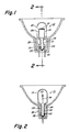
- a miniature lamp 10 comprising a glass envelope 12 including at its lower end a pinch seal 14 also of glass and a glass exhaust tube 18 extending through the seal and having a tip 20 at its lowermost end.
- a tungsten filament 22 Within the envelope 12 is a tungsten filament 22 and two spaced-apart lead-in conductors 24 and 26 between the upper ends of which the filament is connected.
- the lead-in conductors extend from the outside to the inside of the envelope through the pinch seal 14 and in sealed relationship to the glass of the seal.
- a ceramic base 30 For mounting the lamp 10 in a precisely fixed position relative to a reflector (not shown), there is provided a ceramic base 30 that is suitably fixed to the reflector.
- This base 30 contains a cavity 32 in which the pinch seal portion 14 of the envelope is located.
- the space between the seal portion 14 and the interior of the cavity 323 is filled with a hard ceramic cement 34.
- a suitable lamp-basing cement for this purpose is a cement available, for example, from the Sauereisen Cements Company, Pittsburgh, PA, as its #33 cement, or other ceramic cements known to the industry.
- the hard cement 34 fills the entire space between the pinch seal 14 and the surrounding cavity 32 and is in intimate contact with the pinch seal and the tip 20 of the exhaust tube.
- the cement is introduced into this space in an uncured, plastic condition, following which it is cured into a hard condition with the assistance of heat applied to the ceramic base 30.
- the cement expands and contracts both during the curing operation and during lamp cycling, primarily as a result of heating and cooling. While the cement may be selected to have a coefficient of thermal expansion substantially matching that of the glass of the seal 14 and the tip 20, there is still some slight motion of the cement relative to this glass during these temperature excursions. Though this relative motion may be very small, e.g., only three millionths of an inch in some lamp mountings, very high forces, e. g., producing pressures of 5000 psi or more, can be developed on the glass, particularly the relatively fragile tip. These forces can sometimes fracture the tip and thereby ruin the lamp.
- a thin coating 36 of a material much softer than the cured cement 34 about the tip 20 is a thin coating 36 of a material much softer than the cured cement 34 about the tip 20.
- This coating 36 a thin layer of silicon rubber applied to the tip by painting or dipping.
- Another specific embodiment uses a thin slip-on tube of polyfluoroethylene, a material available from E. I. duPont as its Teflon material.
- Teflon material a material available from E. I. duPont as its Teflon material.
- Other materials may also be used provided they are softer than the cement and are capable of staying in place on the tip until the cement cures to maintain its own gap, and provided further that they do not harm the lamp function (as by smoking, melting, shorting, or the like during lamp operation).
- the coating 36 is applied to the tip before the cavity 32 is filled with the cement 34 and preferably remains in place during curing of the cement and thereafter.
- the coating 36 completely fills the entire space between the tip 20 and the surrounding cement.
- the coating receives any forces developed on the tip as a result of relative motion between the surrounding cement and the tip resulting from thermal expansion or contraction of the cement; and the coating yields slightly in response to such forces, thereby protecting the tip from being cracked by these forces.
- the invention comprehends the use of a material around the tip which vaporizes during curing, or during other intervals when high temperatures are developed, to leave a small gap between the tip 20 and the surrounding cement.
- a material around the tip which vaporizes during curing, or during other intervals when high temperatures are developed, to leave a small gap between the tip 20 and the surrounding cement.
- An example of such a material is nitrocellulose, which breaks down at about 180°C.
- the tip 20 is effectively decoupled, or isolated, from the surrounding cement 34 so that the cement is free to expand and contract in response to temperature changes without imposing intolerable loads on the tip.
- the hard cement Since the hard cement is in direct contact with the exterior surface of the seal portion 14 of the lamp envelope about the entire periphery of the seal portion, the lamp is rigidly fixed with respect to the base and is not free to move with respect to the base; and such rigid fixation of the envelope is present even though the thickness of the yieldable layer 36 might substantially exceed that illustrated. In other words, the maximum thickness of coating 36 is not critical and can be varied within reasonable limits without affecting the ability of the mounting to rigidly fix the envelope.
- the hard cement contacts the seal portion 14 about substantially the entire exterior surface of the seal portion, excluding the tip 20, that is located within the cement.
- the incorporation of the thin layer 36 on the tip does not detract from the capability of the hard cement to precisely fix the lamp within the base 30.
- the presence of soft layer 36 detract from the ability of the cement to withstand the high temperatures of lamp operation and to continue its function of precisely fixing the lamp within the base 30.
- One type of ceramic cement 34 which is used in the mounting can withstand temperatures up to 400°C without deterioration, whereas the maximum temperatures developed in the cement by most lamps for this application is in the neighborhood of 200°C.
Landscapes
- Engineering & Computer Science (AREA)
- General Engineering & Computer Science (AREA)
- Vessels And Coating Films For Discharge Lamps (AREA)
Applications Claiming Priority (2)
| Application Number | Priority Date | Filing Date | Title |
|---|---|---|---|
| US38246489A | 1989-07-20 | 1989-07-20 | |
| US382464 | 1989-07-20 |
Publications (3)
| Publication Number | Publication Date |
|---|---|
| EP0409553A2 true EP0409553A2 (de) | 1991-01-23 |
| EP0409553A3 EP0409553A3 (en) | 1992-01-08 |
| EP0409553B1 EP0409553B1 (de) | 1994-11-30 |
Family
ID=23509063
Family Applications (1)
| Application Number | Title | Priority Date | Filing Date |
|---|---|---|---|
| EP90307791A Expired - Lifetime EP0409553B1 (de) | 1989-07-20 | 1990-07-17 | Montage einer Lampe |
Country Status (5)
| Country | Link |
|---|---|
| US (1) | US5126631A (de) |
| EP (1) | EP0409553B1 (de) |
| JP (1) | JPH077664B2 (de) |
| CA (1) | CA2017473A1 (de) |
| DE (1) | DE69014456T2 (de) |
Cited By (1)
| Publication number | Priority date | Publication date | Assignee | Title |
|---|---|---|---|---|
| WO2007110318A1 (de) * | 2006-03-28 | 2007-10-04 | Osram Gesellschaft mit beschränkter Haftung | Verfahren zur herstellung eines elektrisch isolierenden vergusskörpers und ein sockel für eine lampe |
Families Citing this family (2)
| Publication number | Priority date | Publication date | Assignee | Title |
|---|---|---|---|---|
| DE69516425T2 (de) * | 1994-08-26 | 2000-10-19 | Koninklijke Philips Electronics N.V., Eindhoven | Elektrische reflektorlampe |
| US7666048B1 (en) * | 2008-08-01 | 2010-02-23 | Tech Patent Licensing, Llc | Method for securing a miniature bulb in a holder |
Family Cites Families (8)
| Publication number | Priority date | Publication date | Assignee | Title |
|---|---|---|---|---|
| US586055A (en) * | 1897-07-06 | Manufacttiee of incandescent lamps | ||
| US3458747A (en) * | 1966-10-03 | 1969-07-29 | Westinghouse Electric Corp | Electric lamp with improved integrally-molded foamed plastic base having internal stress-relieving means |
| US4126810A (en) * | 1976-06-01 | 1978-11-21 | General Electric Company | Ceramic base for glass halogen lamps |
| US4130774A (en) * | 1977-11-14 | 1978-12-19 | Gte Sylvania Incorporated | Flash tube having improved end cap construction |
| NL7904881A (nl) * | 1979-06-22 | 1980-12-24 | Philips Nv | Lamp-reflector eenheid. |
| US4463278A (en) * | 1982-05-21 | 1984-07-31 | General Electric Company | Lamp unit having accurately positioned filament |
| US4728847A (en) * | 1985-05-17 | 1988-03-01 | U.S. Philips Corporation | Electric lamp having an envelope with an intermediate zirconium oxide coated layer |
| JPS6355847A (ja) * | 1986-08-26 | 1988-03-10 | 西堀 稔 | 電球の凹面反射鏡への接着構造とその接着方法 |
-
1990
- 1990-05-24 CA CA002017473A patent/CA2017473A1/en not_active Abandoned
- 1990-07-17 EP EP90307791A patent/EP0409553B1/de not_active Expired - Lifetime
- 1990-07-17 DE DE69014456T patent/DE69014456T2/de not_active Expired - Fee Related
- 1990-07-17 JP JP2187336A patent/JPH077664B2/ja not_active Expired - Lifetime
- 1990-12-19 US US07/630,409 patent/US5126631A/en not_active Expired - Fee Related
Cited By (1)
| Publication number | Priority date | Publication date | Assignee | Title |
|---|---|---|---|---|
| WO2007110318A1 (de) * | 2006-03-28 | 2007-10-04 | Osram Gesellschaft mit beschränkter Haftung | Verfahren zur herstellung eines elektrisch isolierenden vergusskörpers und ein sockel für eine lampe |
Also Published As
| Publication number | Publication date |
|---|---|
| JPH03116650A (ja) | 1991-05-17 |
| JPH077664B2 (ja) | 1995-01-30 |
| EP0409553A3 (en) | 1992-01-08 |
| CA2017473A1 (en) | 1991-01-20 |
| EP0409553B1 (de) | 1994-11-30 |
| DE69014456D1 (de) | 1995-01-12 |
| US5126631A (en) | 1992-06-30 |
| DE69014456T2 (de) | 1995-06-14 |
Similar Documents
| Publication | Publication Date | Title |
|---|---|---|
| EP2115372B1 (de) | Lampe für eine kammer für schnelles thermisches verfahren | |
| EP0409553A2 (de) | Montage einer Lampe | |
| JPH04308648A (ja) | 無電極低圧放電ランプ | |
| US4481443A (en) | Short-arc discharge lamp | |
| CN1185681C (zh) | 电灯/反射镜单元 | |
| US4704668A (en) | Sleeve type lamp stabilizer | |
| KR970002169B1 (ko) | 교환가능한 헤드 램프 전구용의 일체로 된 내열성 짐발 장치 | |
| CN100572903C (zh) | 照明设备 | |
| JP2787821B2 (ja) | 高圧放電ランプ | |
| HU203613B (en) | Lamp/reflector unit | |
| JP2009302050A (ja) | 片口金形ランプ | |
| JPH0261090B2 (de) | ||
| KR20090088947A (ko) | 전기 반사기 램프 | |
| US20050047766A1 (en) | Infrared radiation source, use of same, and a method for its manufacture | |
| JP4599358B2 (ja) | ランプ及びランプの製造方法 | |
| CA2459154C (en) | Mounting assembly for high output electrodeless lamp | |
| US4644216A (en) | High-pressure discharge lamp | |
| CN110506182A (zh) | 照明设备、照明器及制造方法 | |
| EP0551647A1 (de) | Reflektorleuchte mit einer mit Lötglas verbundenen Linse und Herstellungsverfahren dafür | |
| JPH0541498Y2 (de) | ||
| KR890000965Y1 (ko) | 고온고압의 노내 (爐內) 가스온도 측정장치 | |
| GB2113001A (en) | Heat shield for vapour discharge lamp | |
| JPH0527204B2 (de) | ||
| JPS5916260A (ja) | 管形白熱電球 | |
| JP2001250514A (ja) | 管型白熱電球 |
Legal Events
| Date | Code | Title | Description |
|---|---|---|---|
| PUAI | Public reference made under article 153(3) epc to a published international application that has entered the european phase |
Free format text: ORIGINAL CODE: 0009012 |
|
| AK | Designated contracting states |
Kind code of ref document: A2 Designated state(s): DE FR GB NL |
|
| PUAL | Search report despatched |
Free format text: ORIGINAL CODE: 0009013 |
|
| AK | Designated contracting states |
Kind code of ref document: A3 Designated state(s): DE FR GB NL |
|
| 17P | Request for examination filed |
Effective date: 19911220 |
|
| 17Q | First examination report despatched |
Effective date: 19930630 |
|
| GRAA | (expected) grant |
Free format text: ORIGINAL CODE: 0009210 |
|
| AK | Designated contracting states |
Kind code of ref document: B1 Designated state(s): DE FR GB NL |
|
| PG25 | Lapsed in a contracting state [announced via postgrant information from national office to epo] |
Ref country code: NL Effective date: 19941130 Ref country code: FR Effective date: 19941130 |
|
| REF | Corresponds to: |
Ref document number: 69014456 Country of ref document: DE Date of ref document: 19950112 |
|
| EN | Fr: translation not filed | ||
| NLV1 | Nl: lapsed or annulled due to failure to fulfill the requirements of art. 29p and 29m of the patents act | ||
| PLBE | No opposition filed within time limit |
Free format text: ORIGINAL CODE: 0009261 |
|
| STAA | Information on the status of an ep patent application or granted ep patent |
Free format text: STATUS: NO OPPOSITION FILED WITHIN TIME LIMIT |
|
| 26N | No opposition filed | ||
| PGFP | Annual fee paid to national office [announced via postgrant information from national office to epo] |
Ref country code: DE Payment date: 19960618 Year of fee payment: 7 |
|
| PGFP | Annual fee paid to national office [announced via postgrant information from national office to epo] |
Ref country code: GB Payment date: 19960626 Year of fee payment: 7 |
|
| PG25 | Lapsed in a contracting state [announced via postgrant information from national office to epo] |
Ref country code: GB Free format text: LAPSE BECAUSE OF NON-PAYMENT OF DUE FEES Effective date: 19970717 |
|
| GBPC | Gb: european patent ceased through non-payment of renewal fee |
Effective date: 19970717 |
|
| PG25 | Lapsed in a contracting state [announced via postgrant information from national office to epo] |
Ref country code: DE Free format text: LAPSE BECAUSE OF NON-PAYMENT OF DUE FEES Effective date: 19980401 |