EP0409429A2 - Unité de commande pour haut-parleur - Google Patents
Unité de commande pour haut-parleur Download PDFInfo
- Publication number
- EP0409429A2 EP0409429A2 EP90307020A EP90307020A EP0409429A2 EP 0409429 A2 EP0409429 A2 EP 0409429A2 EP 90307020 A EP90307020 A EP 90307020A EP 90307020 A EP90307020 A EP 90307020A EP 0409429 A2 EP0409429 A2 EP 0409429A2
- Authority
- EP
- European Patent Office
- Prior art keywords
- drive unit
- damping
- coil
- magnetic circuit
- voice coil
- Prior art date
- Legal status (The legal status is an assumption and is not a legal conclusion. Google has not performed a legal analysis and makes no representation as to the accuracy of the status listed.)
- Withdrawn
Links
Images


Classifications
-
- H—ELECTRICITY
- H04—ELECTRIC COMMUNICATION TECHNIQUE
- H04R—LOUDSPEAKERS, MICROPHONES, GRAMOPHONE PICK-UPS OR LIKE ACOUSTIC ELECTROMECHANICAL TRANSDUCERS; DEAF-AID SETS; PUBLIC ADDRESS SYSTEMS
- H04R9/00—Transducers of moving-coil, moving-strip, or moving-wire type
- H04R9/06—Loudspeakers
- H04R9/063—Loudspeakers using a plurality of acoustic drivers
-
- H—ELECTRICITY
- H04—ELECTRIC COMMUNICATION TECHNIQUE
- H04R—LOUDSPEAKERS, MICROPHONES, GRAMOPHONE PICK-UPS OR LIKE ACOUSTIC ELECTROMECHANICAL TRANSDUCERS; DEAF-AID SETS; PUBLIC ADDRESS SYSTEMS
- H04R3/00—Circuits for transducers, loudspeakers or microphones
- H04R3/002—Damping circuit arrangements for transducers, e.g. motional feedback circuits
Definitions
- the present invention relates generally to loudspeaker drive units for loudspeaker systems, particularly but not exclusively ones in which a loudspeaker is driven by constant current. More particularly the invention relates to such drive units in which the vibrational system of the drive unit can be damped satisfactorily in an electromagnetic fashion.
- the output impedance of the signal source is designed to be substantially zero so that the braking or damping factor becomes substantially zero so that the braking or damping factor becomes substantially infinite. Therefore, the vibrating system of the speaker is damped fairly satisfactorily.
- the vibrating system of the dynamic speaker is applied with a force proportional to the current flowing to its voice coil in accordance with Fleming's left hand rule.
- the dynamic speaker is preferably driven by a constant current system.
- the aforenoted speaker system is driven by a constant current signal source whose output impedance is infinite, current distortion is cancelled out by a non-linear reaction of a magnetic circuit, and it is possible to prevent the speaker system from being affected by the marked rise of electrical resistance brought about by heat generation in the voice coil.
- a dynamic loudspeaker drive unit having a vibrational system which, in use, is driven by an electrical signal to produce sound, the vibrational system including an element which forms part of a first magnetic circuit in which magnetic flux is produced by the electrical signal, comprising
- a second aspect of the invention provides a dynamic loudspeaker drive unit having a magnetic circuit in which, in use, magnetic flux is produced by application of an electrical signal, a voice coil bobbin formed of or comprises an electrically conductive material forming a short-circuited ring and a voice coil wound around said voice coil bobbin, the voice coil and voice coil being located in a magnetic gap of said magnetic circuit.
- Figure 2 is a sectional view of one main portion of a first embodiment of the speaker system according to the present invention
- figure 3 is a schematic diagram showing another main portion of the first embodiment of the speaker system according to the present invention.
- a dynamic speaker 10 wherein a central portion of a cone-type diaphragm 11 is bonded to a bobbin 12.
- a voice coil 13 is wound around one end portion 12a of the bobbin 12, and a peripheral edge portion of the diaphragm 11 is bonded to one end portion of a frame 14.
- a magnetic circuit 15 is comprised of a magnet 16, a pole 17 and a plate 18. The magnetic circuit 15 is secured to the other end of the frame 14, and the voice coil 13 is coaxially provided in the air gap between the pole 17 and the plate 18.
- An electromagnetic braking or damping system 20 is provided, in which a braking or damping coil 23 is wound around the other end portion 12b of the bobbin 12 which is extended forwardly of the speaker in its axial direction.
- a damping magnetic circuit 25, which comprises a magnet 26, is provided so as to surround the damping coil 23.
- This damping coil 23 is provided in the air gap between a pole 27 and a plate 28 of the magnetic circuit 25.
- reference numeral 24 designates a supporting member.
- the voice coil 13 is connected to a drive amplifier that operates as a constant current source 1.
- the damping coil 23 is connected with a semi-fixed variable resistor 29.
- the resistor 29 may be replaced with a proper impedance having a suitable frequency characteristic.
- the damping current i20 also serves as a detecting current relative to the motion of the vibrating system in the speaker 10. Accordingly, by feeding this damping current i20 back to the signal source 1 to thereby carry out the motional feedback, the motion of the vibrating system can be controlled so as to provide a predetermined acoustic reproducing characteristic.
- a stationary coil 22 is opposed to the damping coil 23 in the damping system 20A.
- the coil 22 may be wound around the outer periphery of the pole 27 of the magnetic circuit 25 as shown in figure 4.
- the coil 22 may be provided in the inner peripheral surface of the plate 28.
- the damping coil 23 is short circuited as shown in figure 5, and other portions are formed similarly to those of figures 2 and 3.
- a damping current i 20s of relatively large current value results from dividing the electromotive force e in the coil 23 by the resistance value r23 of the coil 23, thereby satisfactorily damping the diaphragm.
- the above described motional feedback can be easily carried out by using an electromotive force electromagnetically induced in the stationary coil 22.
- the damping coil bodily provided with the vibrating system of the dynamic speaker is provided in the air gap of the damping magnetic circuit which is independent of the magnetic circuit of the speaker and the two ends of the damping coil are terminated by predetermined impedance, it is possible to obtain the speaker system of relatively simple arrangement in which the vibrating system of the speaker driven by a constant current can be properly damped in an electromagnetic fashion.
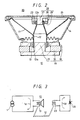
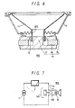
- a third embodiment of the speaker system according to the present invention will be described with reference to figures 6 and 7.
- the arrangement of the speaker system is further simplified, and in figures 6 and 7, like parts corresponding to those of figures 2 and 3 are marked with the same references.
- a dynamic speaker 10S wherein a cone-type diaphragm 11 is bonded at a central portion thereof to a conductive coil bobbin 12S and a voice coil 13 is wound around the bobbin 12S.
- the diaphragm 11 is also bonded at a peripheral edge portion thereof to one end portion of the frame 14.
- the magnetic circuit 15 is comprised of the magnet 16, the pole 17 and the plate 18 and is secured to the other end portion of the frame 14.
- the voice coil 13 is coaxially provided in the air gap between the pole 17 and the plate 18.
- the bobbin 12S is a copper thin plate shaped, for example, as a cylinder and is served as a short circuit ring from an electrical standpoint.
- the voice coil 13 is connected to the drive amplifier provided as the constant current source 1 via a low-pass filter 2 used to separate the frequency band, whereby the speaker 10S functions as a woofer.
- the diaphragm 11, the bobbin 12S and the voice coil 13 are vibrated within the magnetic circuit 15 altogether so that, according to Fleming's right hand rule, the electromotive force e occurs in the bobbin 12S in proportion to the length and the vibrational speed of the bobbin 12S and the magnetic flux density of the magnetic circuit 15, thereby permitting a large current i 12s , dependent on the electromotive force e and a resistance value r 12s of the bobbin 12S in the circumferential direction thereof, to flow.
- This current i 12s produces a force acting in the opposite direction to the vibrational direction of the bobbin 12S to occur, due to the interaction between it and the magnetic circuit 15.
- the resultant force is transmitted to the diaphragm 11, sufficiently damping the diaphragm 11 whose vibration amplitude increases in the low band region.
- the voice coil 13 is wound around the conductive bobbin 12S and is provided within the common magnetic circuit 15, the conductive bobbin 12S and the voice coil 13 are electromagnetically coupled to each other.
- the above described coupling is a transformer of which the voice coil 13 serves as the primary side and the bobbin 12S serves as the secondary side
- its transmission characteristic provides a band-pass type, as shown in a well-known equivalent circuit.
- the inductance of the voice coil 13 is small, the coupling coefficient between the primary and secondary sides decreases greatly in the low frequency band so that the influence of the coupling between the voice coil 13 and the conductive bobbin 12S is negligible.
- the speaker 10S is driven by the constant current in the above described embodiments. If the speaker 10S is driven by a constant voltage, then without being affected by the band-separating network, the vibration system of the speaker 10S can be damped well electromagnetically, similarly as described above.
- the bobbin around which the voice coil of the conductive-type speaker is wound is made of the conductive material to form the short-circuited ring and is provided in the air gap of the magnetic circuit while the drive signal is supplied to the voice coil via the low-pass filter, it is possible to obtain the speaker system of very simple arrangement in which the vibration system of the speaker can be damped well electromagnetically.
- the invention is not limited to speaker systems with a single drive unit, but is equally applicable to systems with multiple drive units such as woofer/tweeter systems and woofer/mid-range/tweeter systems in which at least one of the loudspeaker drive units in accordance with the invention.
Applications Claiming Priority (4)
| Application Number | Priority Date | Filing Date | Title |
|---|---|---|---|
| JP186290/89 | 1989-07-19 | ||
| JP1186290A JPH0388500A (ja) | 1989-07-19 | 1989-07-19 | スピーカ装置 |
| JP85489/89U | 1989-07-20 | ||
| JP1989085489U JPH0324796U (fr) | 1989-07-20 | 1989-07-20 |
Publications (2)
| Publication Number | Publication Date |
|---|---|
| EP0409429A2 true EP0409429A2 (fr) | 1991-01-23 |
| EP0409429A3 EP0409429A3 (en) | 1992-03-18 |
Family
ID=26426494
Family Applications (1)
| Application Number | Title | Priority Date | Filing Date |
|---|---|---|---|
| EP19900307020 Withdrawn EP0409429A3 (en) | 1989-07-19 | 1990-06-27 | Loudspeaker drive unit |
Country Status (1)
| Country | Link |
|---|---|
| EP (1) | EP0409429A3 (fr) |
Cited By (6)
| Publication number | Priority date | Publication date | Assignee | Title |
|---|---|---|---|---|
| US5298245A (en) * | 1991-01-29 | 1994-03-29 | Mycogen Corporation | Bacillus thuringiensis isolates active against dipteran pests |
| WO1995025413A1 (fr) * | 1994-03-17 | 1995-09-21 | Vladimir Walter Kukurudza | Dispositif et procede d'adaptation de haut-parleurs a amortissement automatique |
| SG82078A1 (en) * | 1999-05-26 | 2001-07-24 | Sony Corp | Speaker |
| CN102368281A (zh) * | 2011-11-14 | 2012-03-07 | 浙江中科电声研发中心 | 一种扬声器磁路系统的数值模拟方法 |
| CN104584585A (zh) * | 2012-07-31 | 2015-04-29 | 弗兰霍菲尔运输应用研究公司 | 电声驱动器 |
| CN105069252A (zh) * | 2015-08-26 | 2015-11-18 | 浙江中科电声研发中心 | 轴对称扬声器仿真分析中有限大障板下声压级的近似计算方法 |
Citations (4)
| Publication number | Priority date | Publication date | Assignee | Title |
|---|---|---|---|---|
| GB1591184A (en) * | 1977-04-20 | 1981-06-17 | Ard Anstalt | Electroacoustic transducers |
| EP0134092A2 (fr) * | 1983-08-12 | 1985-03-13 | Linn Products Limited | Haut-parleur à rétroaction motionnelle |
| US4598178A (en) * | 1983-12-16 | 1986-07-01 | Rollins William L | Means for critically damping a dynamic loudspeaker |
| US4783824A (en) * | 1984-10-23 | 1988-11-08 | Trio Kabushiki Kaisha | Speaker unit having two voice coils wound around a common coil bobbin |
-
1990
- 1990-06-27 EP EP19900307020 patent/EP0409429A3/en not_active Withdrawn
Patent Citations (4)
| Publication number | Priority date | Publication date | Assignee | Title |
|---|---|---|---|---|
| GB1591184A (en) * | 1977-04-20 | 1981-06-17 | Ard Anstalt | Electroacoustic transducers |
| EP0134092A2 (fr) * | 1983-08-12 | 1985-03-13 | Linn Products Limited | Haut-parleur à rétroaction motionnelle |
| US4598178A (en) * | 1983-12-16 | 1986-07-01 | Rollins William L | Means for critically damping a dynamic loudspeaker |
| US4783824A (en) * | 1984-10-23 | 1988-11-08 | Trio Kabushiki Kaisha | Speaker unit having two voice coils wound around a common coil bobbin |
Cited By (10)
| Publication number | Priority date | Publication date | Assignee | Title |
|---|---|---|---|---|
| US5298245A (en) * | 1991-01-29 | 1994-03-29 | Mycogen Corporation | Bacillus thuringiensis isolates active against dipteran pests |
| WO1995025413A1 (fr) * | 1994-03-17 | 1995-09-21 | Vladimir Walter Kukurudza | Dispositif et procede d'adaptation de haut-parleurs a amortissement automatique |
| SG82078A1 (en) * | 1999-05-26 | 2001-07-24 | Sony Corp | Speaker |
| US6542617B1 (en) | 1999-05-26 | 2003-04-01 | Sony Corporation | Speaker |
| CN102368281A (zh) * | 2011-11-14 | 2012-03-07 | 浙江中科电声研发中心 | 一种扬声器磁路系统的数值模拟方法 |
| CN104584585A (zh) * | 2012-07-31 | 2015-04-29 | 弗兰霍菲尔运输应用研究公司 | 电声驱动器 |
| CN104584585B (zh) * | 2012-07-31 | 2020-04-28 | 弗劳恩霍夫应用研究促进协会 | 电声驱动器 |
| EP2880872B1 (fr) * | 2012-07-31 | 2021-01-13 | Fraunhofer-Gesellschaft zur Förderung der angewandten Forschung e.V. | Amplificateur électroacoustique |
| CN105069252A (zh) * | 2015-08-26 | 2015-11-18 | 浙江中科电声研发中心 | 轴对称扬声器仿真分析中有限大障板下声压级的近似计算方法 |
| CN105069252B (zh) * | 2015-08-26 | 2018-10-23 | 浙江中科电声研发中心 | 轴对称扬声器仿真分析中有限大障板下声压级的计算方法 |
Also Published As
| Publication number | Publication date |
|---|---|
| EP0409429A3 (en) | 1992-03-18 |
Similar Documents
| Publication | Publication Date | Title |
|---|---|---|
| EP0903961B1 (fr) | Amortissement inductif de l'unité d'actionnement dans un haut-parleur à deux bobines | |
| EP0339855B1 (fr) | Haut-parleur électrodynamique | |
| US4550430A (en) | Sound reproducing system utilizing motional feedback and an improved integrated magnetic structure | |
| US5588065A (en) | Bass reproduction speaker apparatus | |
| US4598178A (en) | Means for critically damping a dynamic loudspeaker | |
| US2860183A (en) | Sound reproducing system | |
| US4256923A (en) | Sound reproducing system utilizing motional feedback and integrated magnetic structure | |
| US4335274A (en) | Sound reproduction system | |
| EP0891117B1 (fr) | Haut-parleur et système de reproduction du son utilisant un tel haut-parleur | |
| US6904158B1 (en) | Speaker apparatus | |
| EP0409429A2 (fr) | Unité de commande pour haut-parleur | |
| US7873180B2 (en) | Voice coil actuator | |
| US3014099A (en) | Electroacoustic transducer | |
| JP3128022B2 (ja) | 同軸スピーカ | |
| WO1999030533A1 (fr) | Transducteur electrodynamique avec diminution de l'inductance equivalente des elements mobiles | |
| US2494918A (en) | Inductively energized electro-dynamic loud-speaker | |
| GB2029669A (en) | Moving coil transducers | |
| JP3835649B2 (ja) | スピーカ装置 | |
| JPS5846798A (ja) | スピ−カ装置 | |
| US3358084A (en) | Electromagnetic sound reproducer | |
| JP3835650B2 (ja) | スピーカ装置 | |
| JPH0364300A (ja) | 音響装置 | |
| JPH0388500A (ja) | スピーカ装置 | |
| JPS5810040B2 (ja) | ムシコウセイスピ−カ | |
| JP2546339Y2 (ja) | スピーカ |
Legal Events
| Date | Code | Title | Description |
|---|---|---|---|
| PUAI | Public reference made under article 153(3) epc to a published international application that has entered the european phase |
Free format text: ORIGINAL CODE: 0009012 |
|
| AK | Designated contracting states |
Kind code of ref document: A2 Designated state(s): DE FR GB |
|
| 17P | Request for examination filed |
Effective date: 19901224 |
|
| PUAL | Search report despatched |
Free format text: ORIGINAL CODE: 0009013 |
|
| AK | Designated contracting states |
Kind code of ref document: A3 Designated state(s): DE FR GB |
|
| 17Q | First examination report despatched |
Effective date: 19931228 |
|
| STAA | Information on the status of an ep patent application or granted ep patent |
Free format text: STATUS: THE APPLICATION IS DEEMED TO BE WITHDRAWN |
|
| 18D | Application deemed to be withdrawn |
Effective date: 19940511 |