EP0409326A2 - Drehzahlsensor - Google Patents
Drehzahlsensor Download PDFInfo
- Publication number
- EP0409326A2 EP0409326A2 EP90201897A EP90201897A EP0409326A2 EP 0409326 A2 EP0409326 A2 EP 0409326A2 EP 90201897 A EP90201897 A EP 90201897A EP 90201897 A EP90201897 A EP 90201897A EP 0409326 A2 EP0409326 A2 EP 0409326A2
- Authority
- EP
- European Patent Office
- Prior art keywords
- output
- amplifier
- voltage
- capacitor
- speed sensor
- Prior art date
- Legal status (The legal status is an assumption and is not a legal conclusion. Google has not performed a legal analysis and makes no representation as to the accuracy of the status listed.)
- Granted
Links
Images


Classifications
-
- G—PHYSICS
- G01—MEASURING; TESTING
- G01P—MEASURING LINEAR OR ANGULAR SPEED, ACCELERATION, DECELERATION, OR SHOCK; INDICATING PRESENCE, ABSENCE, OR DIRECTION, OF MOVEMENT
- G01P3/00—Measuring linear or angular speed; Measuring differences of linear or angular speeds
- G01P3/42—Devices characterised by the use of electric or magnetic means
- G01P3/44—Devices characterised by the use of electric or magnetic means for measuring angular speed
- G01P3/48—Devices characterised by the use of electric or magnetic means for measuring angular speed by measuring frequency of generated current or voltage
- G01P3/481—Devices characterised by the use of electric or magnetic means for measuring angular speed by measuring frequency of generated current or voltage of pulse signals
- G01P3/487—Devices characterised by the use of electric or magnetic means for measuring angular speed by measuring frequency of generated current or voltage of pulse signals delivered by rotating magnets
-
- G—PHYSICS
- G01—MEASURING; TESTING
- G01P—MEASURING LINEAR OR ANGULAR SPEED, ACCELERATION, DECELERATION, OR SHOCK; INDICATING PRESENCE, ABSENCE, OR DIRECTION, OF MOVEMENT
- G01P3/00—Measuring linear or angular speed; Measuring differences of linear or angular speeds
- G01P3/42—Devices characterised by the use of electric or magnetic means
- G01P3/44—Devices characterised by the use of electric or magnetic means for measuring angular speed
- G01P3/48—Devices characterised by the use of electric or magnetic means for measuring angular speed by measuring frequency of generated current or voltage
- G01P3/481—Devices characterised by the use of electric or magnetic means for measuring angular speed by measuring frequency of generated current or voltage of pulse signals
- G01P3/488—Devices characterised by the use of electric or magnetic means for measuring angular speed by measuring frequency of generated current or voltage of pulse signals delivered by variable reluctance detectors
Definitions
- the present invention relates to a rotary speed sensor comprising: a rotary element of ferrous material rotatable about an axis of rotation and having a cross-section, perpendicular to said axis of rotation, which exhibits a surface interruption; magnet means generating a magnetic field along a magnetic path which includes said rotary element, said magnetic field having a tangential component characterized by a base field which may possibly vary relatively slowly, on which base field is superimposed a relatively rapid field variation in response to said surface interruption passing in proximity to said magnet means; transducer means positioned in said magnetic path for detecting the instantaneous tangential component of said magnetic field; and circuit means responsive to said transducer means for detecting the occurrence of said relatively rapid field variation, said circuit means comprising; a first trigger means having first and second differential inputs and an output for forming the output of said circuit means; a first amplifier means fed by said transducer means and having an output coupled to the first input of said trigger means for carrying a signal indicative of the instantaneous tang
- U.S. Patent No. 4,481,469 discloses a rotary speed sensor system for a rotary element of ferrous material which is rotatable about an axis of rotation and has a cross-section, perpendicular to the axis, which exhibits an interrupted surface profile.
- the sensor includes a magnet generating a magnetic field which includes the rotary element, the field exhibiting both radial and tangential components relative to the rotary element; the tangential component changes as the interrupted surface profile passes in proximity to the magnet.
- a Hall element in the magnetic field between the magnet and the rotary element has a voltage output responsive to the changing tangential component of the magnetic field, the voltage output being substantially sinusoidal.
- the sensor further includes circuitry having switching for converting the sinusoidal voltage output to a digital voltage output. The switching has a release point below a first voltage which corresponds to a first field strength and an operating point above a second voltage which corresponds to a second field strength, the second voltage being greater than the first voltage.
- the voltage corresponding to the tangential component of the magnetic field will be a continuous sinusoid. If the rotary element or target is a wheel with one or more spaced apart slots in its surface, the voltage will be flat but for a sinusoidal pulse as each slot passes the sensor.
- the tangential component of the magnetic field at the situs of the Hall element should be zero in the absence of any ferrous material in the field or when the lines of flux on opposed sides of the Hall element extend symmetrically toward the ferrous material, as when the element is aligned with the center line of a gear tooth or the uninterrupted surface of a wheel.
- Figure 1 illustrates a wheel 10 rotating about axis 11 and having an interrupted surface in the form of a slot 12.
- a permanent magnet 14 has a polar end 15 facing the wheel 10, and a Hall sensor 16 inset in the centre of polar end 15.
- the sensor 16 includes a Hall element transducer which is substantially coplanar with the axis 11, so that the tangential component of the magnetic field will ideally be zero when the Hall element is adjacent the uninterrupted surface of the wheel remote from slot 12, or centered over slot 12.
- Figure 2 illustrates the variation in the tangential component of the magnetic field as the slot passes the sensor.
- the solid line shows the field when the air gap between the Hall element and the wheel surface is minimal, and the dashed line shows the tangential field component for a relatively large gap.
- the Hall element translates this varying field to a varying voltage of like profile, which will then be amplified to useful values and used for switching.
- a voltage regulator 17 supplies a regulated voltage to the Hall sensor 16 and to other components of the circuit.
- the output signal of the Hall sensor 16 is amplified by an amplifier 18 having its output connected to the input of a Schmitt trigger 19.
- the Schmitt trigger 19 generates an output of constant amplitude which exists only as long as the input voltage exceeds a certain value. When the input voltage falls below that value (the release point), the output changes amplitude. The output will not return to its original amplitude until the input voltage exceeds a certain value (the operate point) which is higher than the release point.
- the Schmitt trigger 19 may thus be considered as a comparator with hysteresis; it converts an analog input voltage to a digital output voltage having two levels, "0" and "1".
- an NPN transistor 20 in the output, the voltage amplitudes corresponding to these levels can be modified to desired voltage levels utilizing, for example, a pull-up resistor (not shown) for the open collector of the transistor.
- the operate and release points of the Schmitt trigger are fixed. The duration, or even occurrence, of a slot responsive pulse in the digital output voltage is thus dependent on the voltage corresponding to the average or base tangential field component of the magnetic field seen by the Hall sensor 16 when positioned over the uninterrupted portion of the wheel surface.
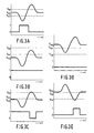
- Figures 3A-3E illustrate how the digital output voltage is affected by the signal voltage V sig at the output of the Schmitt trigger 19 relative to the operate and release points V op and V rel respectively.
- Figure 3A illustrates the situation where the signal voltage at the input is substantially the same as the average of the operate and release points. This is considered ideal, since variations in the air gap which affect the magnitude of the sinusoidal pulse at the input of the Schmitt trigger will not substantially affect the digital output pulse.
- Figure 3B depicts the analog and digital outputs for a speed sensor system having a magnet with an average tangential field component producing an average voltage less than the release point to such an extent that the peak voltage of the sinusoidal pulse is not sufficient to exceed the operate point of the trigger.
- U.S. Patent No. 4,293,814 discloses a crankshaft position sensor which utilities a Hall element whose output depends on the radial component of flux in a magnetic field. The direction of the field is influenced by an actuator having uniformly spaced radially extending sections resembling large gear teeth so that a generally square wave is produced. High voltage peaks are stored on a first capacitor and low voltage peaks are stored on a second capacitor; a comparator triggered at a self-adjusting threshold value between peaks provides an output signal whose waveform will have a constant amplitude without regard to peak variations of the input signal.
- the radial flux component is sensitive to run-out, that is, the effect of changing minimum or maximum air gap about the circumference of the rotary element, which could be caused by eccentricity.
- the threshold voltage could be reached sooner or later than desired, so that the circuitry would have to be desensitized to runout, reducing the air gap for which the sensor is useful.
- the speed sensor according to the invention is characterized in that averaging means are interposed between the output of said amplifier means and the second input of said trigger means for providing a reference signal indicative of the amplitude of said base field.
- the averaging means serve for simultaneously adjusting the release and operate points so that the average thereof at least substantially corresponds to the average or base tangential field component of the magnetic field seen by the Hall element.
- This positioning of the release and operate points relative to a voltage corresponding to the average or base tangential field component is established by feeding one input of a Schmitt trigger with the amplified differential output of the Hall cell and feeding another input of the Schmitt trigger with the output of a voltage averager responsive to the amplified output of the Hall cell.
- the Schmitt trigger thus compares the voltage corresponding to the average magnetic field with the amplified output of the Hall cell, assuring that triggering will occur consistently notwithstanding variations in the orientation and position of the Hall cell and in the magnetic fields established.
- Another feature of the invention is that it is suitable for operation at low RPM such as 10 RPM or less and is suitable for high temperature operation such as 150°C as may be required for operation with an automotive engine. Since the leakage resistance associated with a relatively large value capacitor at such temperatures will cause the capacitor to discharge by leaking current with a significantly rapid time constant, it is necessary when using a capacitor to hold the average voltage to supply the demanded leakage current preventing unwanted discharge.
- Still a further feature of the invention is the provision of means for power-up initialization of the voltage averager.
- FIG. 5 shows a preferred embodiment of the circuit used in the inventive rotary speed sensor system.
- a voltage regulator 17 provides a voltage V reg , preferably about four volts, to the Hall cell independent of the supply voltage V cc .
- I is a current source that keeps the current in the Hall cell constant over temperature.
- the Hall cell outputs an analog voltage differential proportional to the tangential component of the applied magnetic field, which voltage differential varies generally in the form of a sinusoidal pulse as a discontinuity of the ferrous rotary element passes the Hall cell.
- Resistors R1, R2, R3 and R4 and first operational amplifier OPI form a differential amplifier, the resistors being chosen so that R1.R4 equals R2.R3.
- an offset voltage V offset is provided, as from the voltage regulator, having a voltage of about one-half V reg , and is coupled to R4.
- V offset biases output V H ( Figure 6A) to be an always positive signal which varies as the tangential component of magnetic field strength.
- Voltage V H is applied to the first or positive input of a second operational amplifier OP2.
- OP2, resistor R5, and capacitor C1 form a type of voltage averager which closely maintains the base value of V H , herein referred to a V avg , as the voltage V C across capacitor C1.
- a linear RC circuit is not suitable for averaging V H because of the large time constant, in the range of .1 to 50 seconds, necessary to average over several slow rotations of the wheel (e.g. at 1-500 RPM) and the typical high temperature environment of the speed sensor (e.g. 150°C) when in association with an internal combustion engine.
- a large value capacitor such as 1 ⁇ F
- the inherent leakage resistance shunting the capacitor will form a voltage divider with the 10 M ⁇ resistor significantly reducing the voltage across the capacitor.
- the voltage averager is formed by a non-linear circuit in which the voltage V C across capacitor C1 is fed back to the negative input of OP2 and the output voltage V S of OP2 is applied to the capacitor via a resistor R5.
- C1 is in the range of .1 to 10 ⁇ F and R5 is in the range of 1 to 5 M ⁇ .
- V S will normally oscillate between its upper and lower saturation levels, V MAX and V MIN (V MIN being approximately zero), alternately sourcing current into and sinking current from capacitor C1 ( Figure 6B).
- V C This action causes V C to slew an insignificant amount above and below the base voltage V avg which base voltage will be approximately one-half V MAX ( Figure 6C). More time may be spent by OP2 at the upper saturation level V MAX than the lower saturation level V MIN in order to supply, on the average, the leakage current demanded by the inherent leakage resistance of C1 at V avg . Furthermore, V C can track V avg as long as the base voltage changes more slowly than the slew rate.
- V MAX /2.R5.C1 The maximum slew rate of V C due to the sourcing or sinking action, determined approximately by V MAX /2.R5.C1, is chosen sufficiently small (such as in the range of .04 to 20 volts per second), that the variation of V C during the slot responsive pulse is not significant.
- V C is applied to the first or positive input terminal of a third operational amplifier OP3 which is wired as a voltage buffer. As a result of the connection of its output to its second or negative input terminal, the output of OP3 follows V C without loading C1.
- the Schmitt trigger 19 is formed by a fourth operational amplifier OP4 which receives V H at its negative input terminal and has its positive input terminal coupled to the output of OP3 via R6 and to its own output via R7.
- OP4 operates as a comparator between V H and the voltage at its positive input terminal.
- R6 and R7 cause the necessary hysteresis at the positive input terminal of OP4 about the output of OP3, setting the proper operate and release points for V H .
- an initialization circuit comprising an operational amplifier OP5, wired as a comparator with hysteresis in one direction, and an NPN transistor Q2 having its collector coupled to V reg via a relatively low value resistor R g , its emitter coupled to the junction of R5 and C1 and its base connected to the output of OP5.
- OP5 has its negative input terminal connected to the output of OP3, and its positive input terminal connected to V H via a resistor R11 and coupled to its own output via the series combination of a resistor R10 and a diode D1.
- V C and the output of OP3 are zero while V H is positive. This will cause the output of OP5 to go high cutting off D1, turning on Q2, and thereby causing current flow relatively rapidly charging C1 from V reg via R9.
- V C as indicated by the output of OP3, just exceeds V H , OP5 will go low cutting off Q2 and putting D1 into conduction.
- D1 conducts, it causes a hysteresis characteristic in association with R10 and R11.
- R10 and R11 are chosen to cause sufficient hysteresis that the output of OP5 does not again go high in response to the positive-going portion of the slot responsive pulse in V H .
- a diode D2 is preferably provided between V reg and the junction of R5 and C1 directed so as to be reverse biased.
- the purpose of D2 is to supply the leakage current which would otherwise leak from C1 in a number of paths most significantly the leakage current path through the reverse-biased base-emitter junction of Q2.
Landscapes
- Physics & Mathematics (AREA)
- General Physics & Mathematics (AREA)
- Transmission And Conversion Of Sensor Element Output (AREA)
- Measuring Magnetic Variables (AREA)
- Hall/Mr Elements (AREA)
Applications Claiming Priority (2)
| Application Number | Priority Date | Filing Date | Title |
|---|---|---|---|
| US381614 | 1989-07-18 | ||
| US07/381,614 US4992731A (en) | 1988-03-04 | 1989-07-18 | Rotary speed sensor with base line compensation of Hall cell output signal |
Publications (3)
| Publication Number | Publication Date |
|---|---|
| EP0409326A2 true EP0409326A2 (de) | 1991-01-23 |
| EP0409326A3 EP0409326A3 (de) | 1991-03-13 |
| EP0409326B1 EP0409326B1 (de) | 1994-01-19 |
Family
ID=23505699
Family Applications (1)
| Application Number | Title | Priority Date | Filing Date |
|---|---|---|---|
| EP90201897A Expired - Lifetime EP0409326B1 (de) | 1989-07-18 | 1990-07-12 | Drehzahlsensor |
Country Status (5)
| Country | Link |
|---|---|
| US (1) | US4992731A (de) |
| EP (1) | EP0409326B1 (de) |
| JP (1) | JPH0357963A (de) |
| KR (1) | KR910003386A (de) |
| DE (1) | DE69006129D1 (de) |
Cited By (1)
| Publication number | Priority date | Publication date | Assignee | Title |
|---|---|---|---|---|
| GB2276246A (en) * | 1990-10-27 | 1994-09-21 | Birt Electronic Systems Limite | Hall effect sensor |
Families Citing this family (41)
| Publication number | Priority date | Publication date | Assignee | Title |
|---|---|---|---|---|
| JP2796391B2 (ja) * | 1990-01-08 | 1998-09-10 | 株式会社日立製作所 | 物理量検出方法および物理量検出装置あるいはこれらの方法あるいは装置を利用したサーボモータおよびこのサーボモータを使用したパワーステアリング装置 |
| JPH03225223A (ja) * | 1990-01-31 | 1991-10-04 | Komatsu Ltd | 位置検出装置 |
| DE4020228A1 (de) * | 1990-06-26 | 1992-01-02 | Philips Patentverwaltung | Anordnung zum detektieren eines bewegten ferromagnetischen elements |
| DE4133837C2 (de) * | 1991-10-12 | 1994-06-09 | Kostal Leopold Gmbh & Co Kg | Sensoreinrichtung |
| US5264783A (en) * | 1992-01-21 | 1993-11-23 | Allegro Microsystems, Inc. | Contactless magnet-activated proportional controller |
| US5757181A (en) * | 1992-06-22 | 1998-05-26 | Durakool Incorporated | Electronic circuit for automatically compensating for errors in a sensor with an analog output signal |
| US6198275B1 (en) | 1995-06-07 | 2001-03-06 | American Electronic Components | Electronic circuit for automatic DC offset compensation for a linear displacement sensor |
| US5341097A (en) * | 1992-09-29 | 1994-08-23 | Honeywell Inc. | Asymmetrical magnetic position detector |
| US5451868A (en) * | 1993-05-28 | 1995-09-19 | Arthur Allen Manufacturing Company | Changeable divider and index for a vehicle speed and distance transducer including a hall effect sensor |
| US5514955A (en) * | 1994-03-11 | 1996-05-07 | Lake Shore Cryotronics, Inc. | Slim profile digital tachometer including planar block and rotor having spokes and clamp |
| DE9414104U1 (de) * | 1994-08-31 | 1994-11-03 | Siemens AG, 80333 München | Näherungsschalter mit magnetempfindlichem Sensor |
| US5453712A (en) * | 1995-01-25 | 1995-09-26 | Honeywell Inc. | Circuit for accurately discharging a capacitor |
| US5497084A (en) * | 1995-03-03 | 1996-03-05 | Honeywell Inc. | Geartooth sensor with means for selecting a threshold magnitude as a function of the average and minimum values of a signal of magnetic field strength |
| US5670876A (en) * | 1995-11-14 | 1997-09-23 | Fisher Controls International, Inc. | Magnetic displacement sensor including first and second flux paths wherein the first path has a fixed reluctance and a sensor disposed therein |
| US6242908B1 (en) | 1996-01-17 | 2001-06-05 | Allegro Microsystems, Inc. | Detection of passing magnetic articles while adapting the detection threshold |
| US6525531B2 (en) | 1996-01-17 | 2003-02-25 | Allegro, Microsystems, Inc. | Detection of passing magnetic articles while adapting the detection threshold |
| US6297627B1 (en) * | 1996-01-17 | 2001-10-02 | Allegro Microsystems, Inc. | Detection of passing magnetic articles with a peak-to-peak percentage threshold detector having a forcing circuit and automatic gain control |
| EP0793075B1 (de) * | 1996-03-02 | 2002-09-25 | Micronas GmbH | Monolithisch integrierte Sensorschaltung |
| US6285958B1 (en) | 1998-02-12 | 2001-09-04 | American Electronic Components, Inc. | Electronic circuit for automatic compensation of a sensor output signal |
| US6133729A (en) * | 1998-06-17 | 2000-10-17 | Arthur Allen Mfg. Co. | Side looking hall-effect vehicle speed sensor with an alignment positioning system |
| US6111401A (en) * | 1998-06-25 | 2000-08-29 | Arthur Allen Manufacturing Co. | Compact, self contained, hall-effect vehicle speed sensor |
| US6703827B1 (en) | 2000-06-22 | 2004-03-09 | American Electronics Components, Inc. | Electronic circuit for automatic DC offset compensation for a linear displacement sensor |
| US6714003B2 (en) * | 2002-01-25 | 2004-03-30 | American Electronic Components, Inc. | Frequency compensation for rotating target sensor |
| US6690155B2 (en) * | 2002-03-25 | 2004-02-10 | Allegro Microsystems, Inc. | Magnetic gear tooth sensor with Hall cell detector |
| US6909281B2 (en) | 2002-07-03 | 2005-06-21 | Fisher Controls International Llc | Position sensor using a compound magnetic flux source |
| MXPA05008847A (es) * | 2003-02-21 | 2005-10-18 | Fisher Controls Int | Sensor de posicion magnetico con interruptor de efecto hall integrado. |
| US7365530B2 (en) * | 2004-04-08 | 2008-04-29 | Allegro Microsystems, Inc. | Method and apparatus for vibration detection |
| US7253614B2 (en) * | 2005-03-21 | 2007-08-07 | Allegro Microsystems, Inc. | Proximity detector having a sequential flow state machine |
| US7362094B2 (en) * | 2006-01-17 | 2008-04-22 | Allegro Microsystems, Inc. | Methods and apparatus for magnetic article detection |
| JP2008021524A (ja) * | 2006-07-12 | 2008-01-31 | Tokai Rika Co Ltd | 非接触スイッチ |
| US8102136B2 (en) * | 2008-09-25 | 2012-01-24 | Goss International Americas, Inc. | Simultaneous zero verification for motors in a printing press |
| US8598867B2 (en) | 2010-06-04 | 2013-12-03 | Allegro Microsystems, Llc | Circuits and methods for generating a threshold signal used in a motion detector |
| KR20120052448A (ko) * | 2010-11-15 | 2012-05-24 | 삼성전기주식회사 | 정류회로를 이용한 홀 집적회로 |
| US9520871B2 (en) | 2012-01-05 | 2016-12-13 | Allegro Microsystems, Llc | Methods and apparatus for supply voltage transient protection for maintaining a state of a sensor output signal |
| US9329057B2 (en) | 2012-05-31 | 2016-05-03 | Allegro Microsystems, Llc | Gear tooth sensor with peak and threshold detectors |
| US8723512B1 (en) | 2012-11-26 | 2014-05-13 | Allegro Microsystems, Llc | Circuits and methods for generating a threshold signal used in a magnetic field sensor based on a peak signal associated with a prior cycle of a magnetic field signal |
| US9476899B2 (en) | 2013-08-30 | 2016-10-25 | Allegro Microsystems, Llc | Circuits and methods for generating a threshold signal used in a motion detector in accordance with a least common multiple of a set of possible quantities of features upon a target |
| EP3117187B1 (de) | 2014-03-11 | 2018-06-13 | Allegro MicroSystems, LLC | Magnetfeldsensor, welcher einen mindestabstand zwischen schwellenwerten einhält, und entsprechendes erfassungsverfahren |
| JP2015215342A (ja) * | 2014-04-25 | 2015-12-03 | 株式会社デンソー | 回転検出装置及びその製造方法 |
| US11125590B2 (en) | 2019-05-07 | 2021-09-21 | Allegro Microsystems, Llc | System and method for vibration detection with direction change response immunity using a magnetic field sensor |
| US11029176B2 (en) | 2019-05-07 | 2021-06-08 | Allegro Microsystems, Llc | System and method for vibration detection with no loss of position information using a magnetic field sensor |
Citations (4)
| Publication number | Priority date | Publication date | Assignee | Title |
|---|---|---|---|---|
| DE2235056B1 (de) * | 1972-07-17 | 1973-08-23 | Hartmann & Braun Ag, 6000 Frankfurt | Schaltungsanordnung fuer einen induktiven aufnehmer |
| GB2151795A (en) * | 1983-12-23 | 1985-07-24 | Int Standard Electric Corp | Arrangement for determining rotational speed |
| GB2183846A (en) * | 1985-12-05 | 1987-06-10 | Teves Gmbh Alfred | Rotational speed sensor |
| EP0273481A2 (de) * | 1986-11-25 | 1988-07-06 | North American Philips Corporation | Unorientierter Getriebezahnsensor unter Verwendung einer Hall-Zelle |
Family Cites Families (2)
| Publication number | Priority date | Publication date | Assignee | Title |
|---|---|---|---|---|
| US4293814A (en) * | 1979-08-08 | 1981-10-06 | Ford Motor Company | Crankshaft position sensor circuitry for providing stable cyclical output signals without regard to peak to peak variations in sensor signals |
| DE3122376A1 (de) * | 1981-06-05 | 1982-12-23 | Robert Bosch Gmbh, 7000 Stuttgart | Vorrichtung zur erfassung der drehzahl von rotierenden teilen |
-
1989
- 1989-07-18 US US07/381,614 patent/US4992731A/en not_active Expired - Fee Related
-
1990
- 1990-07-12 DE DE90201897T patent/DE69006129D1/de not_active Expired - Lifetime
- 1990-07-12 EP EP90201897A patent/EP0409326B1/de not_active Expired - Lifetime
- 1990-07-16 KR KR1019900010784A patent/KR910003386A/ko not_active Application Discontinuation
- 1990-07-17 JP JP2187359A patent/JPH0357963A/ja active Pending
Patent Citations (4)
| Publication number | Priority date | Publication date | Assignee | Title |
|---|---|---|---|---|
| DE2235056B1 (de) * | 1972-07-17 | 1973-08-23 | Hartmann & Braun Ag, 6000 Frankfurt | Schaltungsanordnung fuer einen induktiven aufnehmer |
| GB2151795A (en) * | 1983-12-23 | 1985-07-24 | Int Standard Electric Corp | Arrangement for determining rotational speed |
| GB2183846A (en) * | 1985-12-05 | 1987-06-10 | Teves Gmbh Alfred | Rotational speed sensor |
| EP0273481A2 (de) * | 1986-11-25 | 1988-07-06 | North American Philips Corporation | Unorientierter Getriebezahnsensor unter Verwendung einer Hall-Zelle |
Cited By (2)
| Publication number | Priority date | Publication date | Assignee | Title |
|---|---|---|---|---|
| GB2276246A (en) * | 1990-10-27 | 1994-09-21 | Birt Electronic Systems Limite | Hall effect sensor |
| GB2276246B (en) * | 1990-10-27 | 1995-03-15 | Birt Electronic Systems Limite | Hall effect sensors |
Also Published As
| Publication number | Publication date |
|---|---|
| US4992731A (en) | 1991-02-12 |
| EP0409326B1 (de) | 1994-01-19 |
| DE69006129D1 (de) | 1994-03-03 |
| EP0409326A3 (de) | 1991-03-13 |
| JPH0357963A (ja) | 1991-03-13 |
| KR910003386A (ko) | 1991-02-27 |
Similar Documents
| Publication | Publication Date | Title |
|---|---|---|
| EP0409326B1 (de) | Drehzahlsensor | |
| EP0024836B1 (de) | Signalzustands-Detektorschaltung | |
| EP0961100B1 (de) | Magnetischer Sensor für Drehlagemessung | |
| US5012207A (en) | Variable reluctance transducer processing circuit for providing an output unaffected by low frequency components | |
| US4367721A (en) | Signal detection circuit with self-adjusting threshold having modulated carrier input | |
| EP0373694A1 (de) | Diagnosevorrichtung für die Verhütung von Überhitzung bei einer stromsteuernden Anlage mit Leistungshalbleiter | |
| US4030468A (en) | Ignition system for internal combustion engines | |
| JPS6318761B2 (de) | ||
| JPH01240819A (ja) | 誘導性測定センサの信号を処理する回路装置 | |
| US6144197A (en) | Rotational speed device with magneto-electric elements | |
| JPS59185665U (ja) | デジタルパルス発生システム | |
| CA1332628C (en) | Cyclic responding electronic speed governor | |
| US4434779A (en) | Circuit for controlling the primary dwell time of ignition transformer | |
| EP0359851A1 (de) | Zündanlage für Innenverbrennungsmaschinen | |
| JPS6155121B2 (de) | ||
| US3844168A (en) | Torque measuring apparatus | |
| GB1588738A (en) | Electrical motor speed regulators | |
| JP2569595B2 (ja) | センサ信号入力装置の接触抵抗検出装置 | |
| KR200215760Y1 (ko) | 가스터빈 엔진 연료밸브 구동전류 제어회로 | |
| EP0619925A4 (de) | Integrator mit geschalteter hysterese für annäherungsschalter. | |
| JPH01177455A (ja) | 内燃機関の点火装置 | |
| JPH06137802A (ja) | 磁束制限器及び磁気分散手段を備えるホール効果位置センサ | |
| GB2117938A (en) | Current driver circuit for an electric-mechanical adjuster | |
| GB2358258A (en) | A temperature controlled cooling fan | |
| JP2935367B2 (ja) | モータのトルクリミット制御回路 |
Legal Events
| Date | Code | Title | Description |
|---|---|---|---|
| PUAI | Public reference made under article 153(3) epc to a published international application that has entered the european phase |
Free format text: ORIGINAL CODE: 0009012 |
|
| AK | Designated contracting states |
Kind code of ref document: A2 Designated state(s): DE FR GB IT SE |
|
| PUAL | Search report despatched |
Free format text: ORIGINAL CODE: 0009013 |
|
| AK | Designated contracting states |
Kind code of ref document: A3 Designated state(s): DE FR GB IT SE |
|
| 17P | Request for examination filed |
Effective date: 19910909 |
|
| 17Q | First examination report despatched |
Effective date: 19921204 |
|
| GRAA | (expected) grant |
Free format text: ORIGINAL CODE: 0009210 |
|
| AK | Designated contracting states |
Kind code of ref document: B1 Designated state(s): DE FR GB IT SE |
|
| PG25 | Lapsed in a contracting state [announced via postgrant information from national office to epo] |
Ref country code: IT Free format text: LAPSE BECAUSE OF FAILURE TO SUBMIT A TRANSLATION OF THE DESCRIPTION OR TO PAY THE FEE WITHIN THE PRESCRIBED TIME-LIMIT;WARNING: LAPSES OF ITALIAN PATENTS WITH EFFECTIVE DATE BEFORE 2007 MAY HAVE OCCURRED AT ANY TIME BEFORE 2007. THE CORRECT EFFECTIVE DATE MAY BE DIFFERENT FROM THE ONE RECORDED. Effective date: 19940119 Ref country code: SE Effective date: 19940119 Ref country code: FR Effective date: 19940119 Ref country code: DE Effective date: 19940119 |
|
| REF | Corresponds to: |
Ref document number: 69006129 Country of ref document: DE Date of ref document: 19940303 |
|
| EN | Fr: translation not filed | ||
| PG25 | Lapsed in a contracting state [announced via postgrant information from national office to epo] |
Ref country code: GB Effective date: 19940712 |
|
| PLBE | No opposition filed within time limit |
Free format text: ORIGINAL CODE: 0009261 |
|
| STAA | Information on the status of an ep patent application or granted ep patent |
Free format text: STATUS: NO OPPOSITION FILED WITHIN TIME LIMIT |
|
| 26N | No opposition filed | ||
| GBPC | Gb: european patent ceased through non-payment of renewal fee |
Effective date: 19940712 |