EP0408303B1 - Aufnehmerspulenanordnung für Mehrkanalsquidmagnetometer - Google Patents
Aufnehmerspulenanordnung für Mehrkanalsquidmagnetometer Download PDFInfo
- Publication number
- EP0408303B1 EP0408303B1 EP90307515A EP90307515A EP0408303B1 EP 0408303 B1 EP0408303 B1 EP 0408303B1 EP 90307515 A EP90307515 A EP 90307515A EP 90307515 A EP90307515 A EP 90307515A EP 0408303 B1 EP0408303 B1 EP 0408303B1
- Authority
- EP
- European Patent Office
- Prior art keywords
- pick
- coil
- coils
- coil assembly
- support body
- Prior art date
- Legal status (The legal status is an assumption and is not a legal conclusion. Google has not performed a legal analysis and makes no representation as to the accuracy of the status listed.)
- Expired - Lifetime
Links
Images


Classifications
-
- G—PHYSICS
- G01—MEASURING; TESTING
- G01R—MEASURING ELECTRIC VARIABLES; MEASURING MAGNETIC VARIABLES
- G01R33/00—Arrangements or instruments for measuring magnetic variables
- G01R33/02—Measuring direction or magnitude of magnetic fields or magnetic flux
- G01R33/022—Measuring gradient
-
- G—PHYSICS
- G01—MEASURING; TESTING
- G01R—MEASURING ELECTRIC VARIABLES; MEASURING MAGNETIC VARIABLES
- G01R33/00—Arrangements or instruments for measuring magnetic variables
- G01R33/02—Measuring direction or magnitude of magnetic fields or magnetic flux
- G01R33/035—Measuring direction or magnitude of magnetic fields or magnetic flux using superconductive devices
- G01R33/0354—SQUIDS
- G01R33/0358—SQUIDS coupling the flux to the SQUID
-
- Y—GENERAL TAGGING OF NEW TECHNOLOGICAL DEVELOPMENTS; GENERAL TAGGING OF CROSS-SECTIONAL TECHNOLOGIES SPANNING OVER SEVERAL SECTIONS OF THE IPC; TECHNICAL SUBJECTS COVERED BY FORMER USPC CROSS-REFERENCE ART COLLECTIONS [XRACs] AND DIGESTS
- Y10—TECHNICAL SUBJECTS COVERED BY FORMER USPC
- Y10S—TECHNICAL SUBJECTS COVERED BY FORMER USPC CROSS-REFERENCE ART COLLECTIONS [XRACs] AND DIGESTS
- Y10S336/00—Inductor devices
- Y10S336/01—Superconductive
Definitions
- the present invention relates to a pick-up coil assembly for a magnetometer using a plurality of super-conducting quantum interference devices (SQUID's).
- SQUID's super-conducting quantum interference devices
- a SQUID is widely used for detecting a weak magnetic field with very high sensitivity. That is, a SQUID can respond to a change in a weak magnetic field based on a quantum interference effect of the magnetic field. Accordingly, a SQUID is mainly utilized for, particularly, a high sensitivity magnetometer having a pick-up coil assembly as a magnetic sensor. A SQUID magnetometer is utilized, for example, in the medical equipment field to measure the weak magnetic field generated by the heart of a human body.
- a detecting stage of a digital SQUID magnetometer may be constituted by a superconductive pick-up coil for detecting a weak magnetic field from an object (human body), a super-conductive input coil provided in the SQUID and magnetically coupled to the pick-up coil, and a superconductive feedback coil magnetically coupled to these coils.
- the pick-up coil assembly is constituted by a plurality of coils (multi-channel), each coil corresponding to one channel, since it is necessary to simultaneously detect the magnetic field over a wide area on the object. For example, about 36 individual pick-up coils are necessary for diagnosing the heart.
- the pick-up coil assembly since the pick-up coil assembly must detect a very weak magnetic field without dispersion of characteristics among pick-up coils, it is necessary to assemble the pick-up coil assembly with very high precision, particularly structural precision, so as to have high uniformity among coils.
- EP-A-0 313 132 discloses a multi-channel SQUID magnetometer having a pick-up coil assembly with the features of the preamble of accompanying claim 1.
- each channel is equipped with an assembly in which a SQUID is integrated with first and second pick-up coils on the same substrate.
- EP-A-0 184 670 discloses a pick-up coil assembly for a SQUID magnetometer in which multiple pick-up coils are formed on the same cylindrical support body, thereby allowing a second-order gradiometer to be formed using a single substrate.
- a pick-up coil assembly for a multi-channel SQUID gradiometer comprising a base plate, and a plurality of pick-up coil units mounted on the base plate, each of the units having a support body, a plurality of pick-up coils and connection lines, the pick-up coils and the connection lines being formed by a lithography technique on the support body; characterised in that: a plurality of support bars are fixedly mounted on the base plate so as to form an array configuration; each of the pick-up coil units is made up of a first and a second pick-up coil block having respective support bodies which are fixedly mounted on one of the support bars; each of the pick-up coil blocks has a pair of said pick-up coils, and connection pads which are also formed by said lithography technique on the support body; and in that the pick-up coil assembly constitutes a detecting stage of the gradiometer, said detecting stage being provided separately from a SQUID and being coupled thereto via an input coil.
- An embodiment of the present invention can provide such a pick-up coil assembly for a multi-channel SQUID gradiometer, having high precision and high uniformity of characteristics detected among coils.
- the pick-up coil assembly includes insulating spacers, one of which is provided between the first and second pick-up coil block of each pick-up coil unit to insulate between the pick-up coils.
- the pair of pick-up coils of each block forms a first order gradiometer.
- a pick-up coil of the first block is cross-connected to a pick-up coil of the second block by superconductive wires so as to form a second order gradiometer.
- the support body includes a penetrating hole along with a longitudinal axis for inserting the support bar.
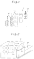
- Figure 1 shows one type of pick-up coil assembly.
- This type of pick-up coil assembly 1 is constituted by a plurality of pick-up coils 11.
- Each of pick-up coils 11 has a coil bobbin 111 and a superconductive wire 112.
- the coil bobbin 111 is made of a non-magnetized material.
- the superconductive wire 112 is manually wound on the coil bobbin 111 along with a groove (not shown) to form the first or second order gradiometer shown in Fig. 3 or Fig. 4.
- Figure 2 is another example of a pick-up coil assembly for a multi-channel SQUID magnetometer. This type of the pick-up coil assembly is disclosed in Japanese Unexamined Patent Publication (Kokai) No. 59-133474 (corresponding U.S. Serial No. 4,749,946).
- This type of the pick-up coil assembly 1 is constituted by a support body 20 and a plurality of pick-up coils 21a and 21b provided on the support body 20.
- the pick-up coils 21b are provided on opposite surfaces of the pick-up coil 21a, and connected thereto by a connection line 22.
- each of pick-up coils 21a and 21b are formed by a lithography technique which is widely utilized in the field of integrated circuit (IC) manufacturing.
- the 36 coils are arranged in a matrix of 6 columns x 6 rows. Accordingly, since the diameter of one pick-up coil is about 2 to 3 cm, the size of one surface of the support body 20 becomes 15 cm x 15 cm to provide the pick-up coil assembly.
- a large lithography device which can print such large numbers of lithography patterns (i.e., a plurality of pick-up coils 21a and 21b) on both surfaces of the support body 20.
- connection lines 22 it is difficult to provide the lithography patterns connecting the pick-up coils 21a and 21b (i.e., connection lines 22) because very fine adjustment of the position is necessary for printing the above patterns in an additional manufacturing process.
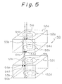
- Figure 5 is a schematic view of a pick-up coil unit of an assembly embodying the invention.
- the pick-up coil unit is constituted by a first and second pick-up coil blocks.
- 50a and 50b denote support bodies made of, for example, glass block or bulk of silicon.
- Each of the support bodies 50a and 50b has a square configuration in a sectional view, and comprises penetrating holes 51a and 51b along a longitudinal axis thereof.
- the support body 50a comprises only one pair of the pick-up coils 52a and 52b on both plane surfaces around the penetrating hole 51a. That is, the first order gradiometer is formed by a pair of pick-up coils 52a and 52b.
- the support body 50b including a pair of pick-up coils 52c and 52d has the same structure as the support body 50a.
- these pick-up coils 52a, 52b, and 52c, 52d are made by the lithography technique through the manufacturing process as shown in detail in Fig. 8.
- the upper pick-up coil 52a is connected to the lower pick-up coil 52b through the connection line 53a printed by the lithography technique.
- the upper pick-up coil 52c is connected to the lower pick-up coil 52d through the connection line 53b printed by the lithography technique.
- the lithography technique of the connection lines 53a and 53b is not so difficult to manufacture because the support bodies 50a and 50b are very small.
- the pick-up coil 52b of the upper block 50a is cross-connected to the pick-up coil 52c of the lower block 50b through the superconductive line 53c so as to form the second order gradiometer as shown in Fig. 4.
- 54a to 54f denote connection pads.
- the pad 54a is connected to an input stage (see Fig. 11) of the magnetometer, the pad 54b is connected to the pad 54c, the pad 54c is connected to the pad 54f, and the pad 54d is connected to the pad 54e.
- connection pad 54 is also formed by the lithography technique, and the connection between the pads is effected by a superconductive soldering or screw for a superconductive line.
- arrows denote the direction of the current flowing in the pick-up coil.
- a pick-up coil assembly embodying the present invention is constituted by a plurality of pick-up coil units 50 shown in Fig. 5, by arranging the pick-up coil units in the matrix configuration as explained in detail hereinafter.
- Figure 6 is a view for explaining assembly steps of the pick-up coil assembly.
- 61 denotes a bar.
- 63 denotes a spacer for insulating between pick-up coils.
- a plurality of bars 61 are fixedly arranged in a base plate 62 in a matrix configuration.
- the support body 50b is inserted onto the bar 61 through the penetrating hole 51b; second, the spacer 63 is inserted onto the bar 61; third, the support body 50a is inserted onto the bar 61 through the penetrating hole 51a; finally, the pick-up coil 52b is connected to the pick-up coil 52c as explained above, then, the support bodies 50a and 50b are integrated as the pick-up unit 50.
- Figure 7 is a schematic view of the pick-up coil assembly.
- a plurality of the pick-up coil units 50 are arranged in the matrix configuration so as to form the pick-up coil assembly having, for example, 36 (6 x 6) pick-up coil units.
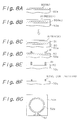
- Figures 8A to 8G are views for explaining a manufacturing process of the pick-up coil using the lithography technique.
- 80 denotes a niobium (Nb) thin layer, 81 a resist layer, and 82 a mask film.
- Nb niobium
- the niobium thin layer 80 is formed on the glass (or silicon: Si) body 50a by using a sputtering method.
- the resist material is spread on the niobium thin layer 80, the spread resist material is baked to be harden by using a pre-bake method, and the resist layer 81 is formed on the glass body 50a.
- the mask film 82 having the pattern of the pick-up coil is put on the resist layer 81.
- Fig. 8D after exposing, developing and heating are performed by using a post-bake method so that the resist layer 81 remains along with the pattern of the pick-up coil 52a.
- niobium thin layer 80 which is not covered by the resist layer 81 is eliminated by using a dry-etching method.
- the resist layer 81 is eliminated by a solvent, for example, an acetone solvent, and only the niobium thin layer 80 is formed on the glass body 50a.
- a solvent for example, an acetone solvent
- Figure 9 is a view for explaining a wire pattern on the base plate.
- the wire pattern 64 is formed by a printed circuit technique on the base plate 62.
- Figures 10A to 10C illustrate alternative forms of the support body shown in Fig. 5.
- the support body 50a ⁇ is formed by an octagonal or hexagonal configuration.
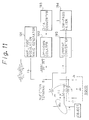
- FIG 11 is a schematic block diagram of a digital SQUID control system used for the digital SQUID magnetometer.
- L4 denotes a pick-up coil.
- the SQUID is constituted by two Josephson devices and a superconductive coil L2.
- L1 denotes a superconductive input coil
- L3 denotes a superconductive feedback coil.
- Reference number 191 denotes an amplitude modulation wave generator, 192 an up-down counter, 193 a digital-to-analog converter, 194 a low-pass filter and 195 a current converter.
- a pick-up coil assembly embodying the present invention can be applied to the pick-up coil L4.
- the pick-up coil L4 detects weak magnetic field ⁇ c irradiated from the object to be measured. Accordingly, the current flows input coil L1 in response to change of the magnetic field ⁇ c .
- the coil L2 of the SQUID is arranged in the vicinity of the input coil L1 so as to obtain magnetic coupling with each other.
- an alternating bias current I b generated from the generator 191 flows in the SQUID through an injection terminal B.
- the bias current I b is superimposed on the current flowing in the SQUID.
- Reference I f denotes a feedback current flowing from the converter 195 to the coil L3.
- a pick-up coil assembly embodying the present invention is constituted by a plurality of pick-up coils arranged in an array configuration (for example, matrix) for enabling multi-channel measurement of magnetic field.
- Such a coil assembly may be advantageously utilized in a digital SQUID magnetometer.
Landscapes
- Physics & Mathematics (AREA)
- Condensed Matter Physics & Semiconductors (AREA)
- General Physics & Mathematics (AREA)
- Measuring Magnetic Variables (AREA)
- Measurement And Recording Of Electrical Phenomena And Electrical Characteristics Of The Living Body (AREA)
Claims (5)
- Eine Aufnahmespulenbaugruppe für ein vielkanaliges SQUID-Gradometer, mit einer Basisplatte (62) und einer Vielzahl von Aufnahmespuleneinheiten, die auf der Basisplatte (62) montiert sind, von welchen Einheiten jede einen Stützkörper (50a, 50b), eine Vielzahl von Aufnahmespulen (52a, 52b; 52c, 52d) und Verbindungsleitungen hat, welche Aufnahmespulen und Verbindungsleitungen (53a, 53b) durch ein Lithografieverfahren auf dem Stützkörper (50a, 50b) gebildet sind;
dadurch gekennzeichnet, daß:
eine Vielzahl von Stützstäben (61) auf der Basisplatte (62) fest montiert ist, um eine Array-Konfiguration zu bilden;
jede der Aufnahmespuleneinheiten (50) aus einem ersten und einem zweiten Aufnahmespulenblock gebildet ist, die jeweilige Stützkörper (50a, 50b) haben, die auf einem der Stützstäbe (61) fest montiert sind;
jeder der Aufnahmespulenblöcke ein Paar der genannten Aufnahmespulen (52a, 52b; 52c, 52d) hat, und Verbindungsstellen (54a...54f), die auch durch das genannte Lithografieverfahren auf dem Stützkörper (50a, 50b) gebildet sind;
und daß die Aufnahmespulenbaugruppe eine Detektionsstufe (L4) des Gradometers bildet, welche Detektionsstufe separat von einem SQUID (L2, J1, J2) vorgesehen ist und über eine Eingangsspule (L1) mit ihm gekoppelt ist. - Eine Aufnahmespulenbaugruppe nach Anspruch 1, ferner mit Isolationsabstandshaltern (63), wovon einer zwischen dem ersten und dem zweiten Aufnahmespulenblock von jeder Aufnahmespuleneinheit (50) vorgesehen ist, zum Isolieren zwischen den Aufnahmespulen (52b, 52c).
- Eine Aufnahmespulenbaugruppe nach Anspruch 1, bei der das Paar von Aufnahmespulen (52a, 52b; 52c, 52d) von jedem Block einen Gradometer erster Ordnung bildet.
- Eine Aufnahmespulenbaugruppe nach Anspruch 1, bei der eine Aufnahmespule (52b) des ersten Blocks mit einer Aufnahmespule (52c) des zweiten Blocks durch supraleitfähige Drähte (53c) querverbunden ist, um einen Gradometer zweiter Ordnung zu bilden.
- Eine Aufnahmespulenbaugruppe nach Anspruch 1, bei der der Stützkörper (50a, 50b) längs seiner Längsachse ein Durchgangsloch (51a, 51b) zum Einsetzen des Stützstabes (61) umfaßt.
Priority Applications (1)
| Application Number | Priority Date | Filing Date | Title |
|---|---|---|---|
| EP94111856A EP0625712B1 (de) | 1989-07-10 | 1990-07-10 | Aufnehmerspulenanordnung für Mehrkanal-SQUID-Magnetfeld-Gradiometer |
Applications Claiming Priority (4)
| Application Number | Priority Date | Filing Date | Title |
|---|---|---|---|
| JP178858/89 | 1989-07-10 | ||
| JP1178858A JPH0342588A (ja) | 1989-07-10 | 1989-07-10 | 多チャンネルsquid磁束計用ピックアップコイル |
| JP1223869A JPH0385139A (ja) | 1989-08-30 | 1989-08-30 | 生体磁気測定装置のピックアップコイル |
| JP223869/89 | 1989-08-30 |
Related Child Applications (1)
| Application Number | Title | Priority Date | Filing Date |
|---|---|---|---|
| EP94111856.4 Division-Into | 1994-07-29 |
Publications (3)
| Publication Number | Publication Date |
|---|---|
| EP0408303A2 EP0408303A2 (de) | 1991-01-16 |
| EP0408303A3 EP0408303A3 (en) | 1992-07-15 |
| EP0408303B1 true EP0408303B1 (de) | 1995-09-27 |
Family
ID=26498910
Family Applications (2)
| Application Number | Title | Priority Date | Filing Date |
|---|---|---|---|
| EP90307515A Expired - Lifetime EP0408303B1 (de) | 1989-07-10 | 1990-07-10 | Aufnehmerspulenanordnung für Mehrkanalsquidmagnetometer |
| EP94111856A Expired - Lifetime EP0625712B1 (de) | 1989-07-10 | 1990-07-10 | Aufnehmerspulenanordnung für Mehrkanal-SQUID-Magnetfeld-Gradiometer |
Family Applications After (1)
| Application Number | Title | Priority Date | Filing Date |
|---|---|---|---|
| EP94111856A Expired - Lifetime EP0625712B1 (de) | 1989-07-10 | 1990-07-10 | Aufnehmerspulenanordnung für Mehrkanal-SQUID-Magnetfeld-Gradiometer |
Country Status (3)
| Country | Link |
|---|---|
| US (1) | US5451871A (de) |
| EP (2) | EP0408303B1 (de) |
| DE (2) | DE69031505T2 (de) |
Families Citing this family (5)
| Publication number | Priority date | Publication date | Assignee | Title |
|---|---|---|---|---|
| US5307042A (en) * | 1992-02-19 | 1994-04-26 | B&D Liquidation Corp. | Search coil frame assembly for metal and method for making same |
| JPH0984777A (ja) * | 1995-09-25 | 1997-03-31 | Toshiba Corp | 生体磁場計測装置 |
| US7615385B2 (en) | 2006-09-20 | 2009-11-10 | Hypres, Inc | Double-masking technique for increasing fabrication yield in superconducting electronics |
| EP2145197A4 (de) * | 2007-05-04 | 2011-07-27 | California Inst Of Techn | Geometrien für supraleitende erfassungsspulen für systeme auf squid-basis |
| WO2008137485A2 (en) * | 2007-05-04 | 2008-11-13 | California Institute Of Technology | Low field squid mri devices, components and methods |
Family Cites Families (10)
| Publication number | Priority date | Publication date | Assignee | Title |
|---|---|---|---|---|
| US2983865A (en) * | 1946-04-01 | 1961-05-09 | Wenner Frank | Mine detector |
| US3546580A (en) * | 1967-06-06 | 1970-12-08 | North American Rockwell | Magnetic field variometer using a low noise amplifier and a coil-core arrangement of minimum weight and maximum sensitivity |
| IT1171429B (it) * | 1981-07-31 | 1987-06-10 | Consiglio Nazionale Ricerche | Perfezionamento nei dispositivo per misure biomagnetiche utilizzanti gradiometri a seconda derivata |
| DE3247543A1 (de) * | 1982-12-22 | 1984-06-28 | Siemens AG, 1000 Berlin und 8000 München | Vorrichtung zur mehrkanaligen messung schwacher, sich aendernder magnetfelder und verfahren zu ihrer herstellung |
| DE3324208A1 (de) * | 1983-07-05 | 1985-01-17 | Siemens AG, 1000 Berlin und 8000 München | Supraleitendes gradiometerspulensystem fuer eine vorrichtung zur mehrkanaligen messung schwacher, sich aendernder magnetfelder |
| US4694567A (en) * | 1984-11-19 | 1987-09-22 | Siemens Aktiengesellschaft | Method for making a superconducting gradiometer having a three-dimensional structure and associated connecting lines for a device for measuring weak magnetic fields |
| EP0185186B1 (de) * | 1984-11-19 | 1989-02-01 | Siemens Aktiengesellschaft | Verfahren zur Herstellung eines dreidimensionalen Gradiometers für eine Vorrichtung zur ein- oder mehrkanaligen Messung schwacher Magnetfelder |
| DE3515199A1 (de) * | 1985-04-26 | 1986-11-06 | Siemens AG, 1000 Berlin und 8000 München | Vorrichtung zur messung schwacher magnetfelder mit mehreren gradiometern |
| DE3735668A1 (de) * | 1987-10-22 | 1989-05-03 | Philips Patentverwaltung | Vorrichtung zur mehrkanaligen messung schwacher magnetfelder |
| US4947118A (en) * | 1988-11-21 | 1990-08-07 | Fujitsu Limited | Digital squid system adaptive for integrated circuit construction and having high accuracy |
-
1990
- 1990-07-10 EP EP90307515A patent/EP0408303B1/de not_active Expired - Lifetime
- 1990-07-10 US US07/550,691 patent/US5451871A/en not_active Expired - Fee Related
- 1990-07-10 DE DE69031505T patent/DE69031505T2/de not_active Expired - Fee Related
- 1990-07-10 EP EP94111856A patent/EP0625712B1/de not_active Expired - Lifetime
- 1990-07-10 DE DE69022649T patent/DE69022649T2/de not_active Expired - Fee Related
Non-Patent Citations (1)
| Title |
|---|
| Rev. Sci. Instrum., vol. 53, no. 12, December 1982, pages 1815, 1826, 1827 (from G.L. Romani et al.: "Biomagnetic Instrumentation", pages 1815-1845) * |
Also Published As
| Publication number | Publication date |
|---|---|
| US5451871A (en) | 1995-09-19 |
| EP0625712B1 (de) | 1997-09-24 |
| DE69022649D1 (de) | 1995-11-02 |
| DE69022649T2 (de) | 1996-02-29 |
| EP0625712A3 (de) | 1995-01-25 |
| EP0408303A3 (en) | 1992-07-15 |
| EP0625712A2 (de) | 1994-11-23 |
| EP0408303A2 (de) | 1991-01-16 |
| DE69031505T2 (de) | 1998-02-05 |
| DE69031505D1 (de) | 1997-10-30 |
Similar Documents
| Publication | Publication Date | Title |
|---|---|---|
| EP1387179B1 (de) | In einer Leiterplatte integrierte Förstersonde und dessen Herstellungsverfahren | |
| EP0317775B1 (de) | Stabilisierte, selbstabgeschirmte Gradientespulen | |
| US4749946A (en) | Device for the multi-channel measurement of weak variable magnetic fields with squids and superconducting gradiometers arranged on a common substrate | |
| JP3093135B2 (ja) | 平面ソレノイド及び平面ソレノイドを用いたsquid磁力計 | |
| EP0147655B1 (de) | Miniatur-SQUID-Susceptibilitätsmessgerät | |
| US4613817A (en) | Superconducting gradiometer coil system for an apparatus for the multi-channel measurement of weak nonstationary magnetic fields | |
| US4693000A (en) | Method for manufacturing a three-dimensional gradiometer for a device for the single or multi-channel measurement of weak magnetic fields | |
| EP0408303B1 (de) | Aufnehmerspulenanordnung für Mehrkanalsquidmagnetometer | |
| CA2057454C (en) | Pickup coil for measurement of magnetic fields | |
| US4694567A (en) | Method for making a superconducting gradiometer having a three-dimensional structure and associated connecting lines for a device for measuring weak magnetic fields | |
| JPH08313609A (ja) | 径方向微分型squid磁束計 | |
| Lee et al. | A whole-head magnetoencephalography system with compact axial gradiometerstructure | |
| EP0525533B1 (de) | Supraleitende Detektionsspulen | |
| JP3018540B2 (ja) | 3軸型グラジオメータ | |
| US5548262A (en) | Flux transformer formed of an oxide superconducting thin film and method for manufacturing the same | |
| JP2909790B2 (ja) | 超伝導検出コイル | |
| JP3156396B2 (ja) | 差動型squid磁束計及びこれを用いた生体磁場計測装置 | |
| JPH0342588A (ja) | 多チャンネルsquid磁束計用ピックアップコイル | |
| JPH0499979A (ja) | Squid磁束計 | |
| JP2592965Y2 (ja) | 超伝導検出コイル | |
| JP3206198B2 (ja) | Dc−squid磁束計 | |
| EP0583640A1 (de) | Magnetische Aufnehmerspule | |
| JPH03199985A (ja) | 微小磁界計測ユニット | |
| JPH04125981A (ja) | Squid磁束計 | |
| JPH045587A (ja) | 高感度磁場検出器 |
Legal Events
| Date | Code | Title | Description |
|---|---|---|---|
| PUAI | Public reference made under article 153(3) epc to a published international application that has entered the european phase |
Free format text: ORIGINAL CODE: 0009012 |
|
| AK | Designated contracting states |
Kind code of ref document: A2 Designated state(s): DE FR GB |
|
| PUAL | Search report despatched |
Free format text: ORIGINAL CODE: 0009013 |
|
| AK | Designated contracting states |
Kind code of ref document: A3 Designated state(s): DE FR GB |
|
| 17P | Request for examination filed |
Effective date: 19920901 |
|
| 17Q | First examination report despatched |
Effective date: 19940210 |
|
| GRAA | (expected) grant |
Free format text: ORIGINAL CODE: 0009210 |
|
| AK | Designated contracting states |
Kind code of ref document: B1 Designated state(s): DE FR GB |
|
| XX | Miscellaneous (additional remarks) |
Free format text: TEILANMELDUNG 94111856.4 EINGEREICHT AM 29/07/94. |
|
| REF | Corresponds to: |
Ref document number: 69022649 Country of ref document: DE Date of ref document: 19951102 |
|
| ET | Fr: translation filed | ||
| PLBE | No opposition filed within time limit |
Free format text: ORIGINAL CODE: 0009261 |
|
| STAA | Information on the status of an ep patent application or granted ep patent |
Free format text: STATUS: NO OPPOSITION FILED WITHIN TIME LIMIT |
|
| 26N | No opposition filed | ||
| PGFP | Annual fee paid to national office [announced via postgrant information from national office to epo] |
Ref country code: GB Payment date: 19970701 Year of fee payment: 8 |
|
| PGFP | Annual fee paid to national office [announced via postgrant information from national office to epo] |
Ref country code: FR Payment date: 19970709 Year of fee payment: 8 |
|
| PGFP | Annual fee paid to national office [announced via postgrant information from national office to epo] |
Ref country code: DE Payment date: 19970718 Year of fee payment: 8 |
|
| PG25 | Lapsed in a contracting state [announced via postgrant information from national office to epo] |
Ref country code: GB Free format text: LAPSE BECAUSE OF NON-PAYMENT OF DUE FEES Effective date: 19980710 |
|
| GBPC | Gb: european patent ceased through non-payment of renewal fee |
Effective date: 19980710 |
|
| PG25 | Lapsed in a contracting state [announced via postgrant information from national office to epo] |
Ref country code: FR Free format text: LAPSE BECAUSE OF NON-PAYMENT OF DUE FEES Effective date: 19990331 |
|
| PG25 | Lapsed in a contracting state [announced via postgrant information from national office to epo] |
Ref country code: DE Free format text: LAPSE BECAUSE OF NON-PAYMENT OF DUE FEES Effective date: 19990501 |
|
| REG | Reference to a national code |
Ref country code: FR Ref legal event code: ST |