EP0408081B1 - Zylinderkopf-Schmiersystem einer Brennkraftmaschine - Google Patents
Zylinderkopf-Schmiersystem einer Brennkraftmaschine Download PDFInfo
- Publication number
- EP0408081B1 EP0408081B1 EP19900113491 EP90113491A EP0408081B1 EP 0408081 B1 EP0408081 B1 EP 0408081B1 EP 19900113491 EP19900113491 EP 19900113491 EP 90113491 A EP90113491 A EP 90113491A EP 0408081 B1 EP0408081 B1 EP 0408081B1
- Authority
- EP
- European Patent Office
- Prior art keywords
- cylinder head
- lubricating system
- series
- camshaft
- lash adjustors
- Prior art date
- Legal status (The legal status is an assumption and is not a legal conclusion. Google has not performed a legal analysis and makes no representation as to the accuracy of the status listed.)
- Expired - Lifetime
Links
Images


Classifications
-
- F—MECHANICAL ENGINEERING; LIGHTING; HEATING; WEAPONS; BLASTING
- F01—MACHINES OR ENGINES IN GENERAL; ENGINE PLANTS IN GENERAL; STEAM ENGINES
- F01M—LUBRICATING OF MACHINES OR ENGINES IN GENERAL; LUBRICATING INTERNAL COMBUSTION ENGINES; CRANKCASE VENTILATING
- F01M9/00—Lubrication means having pertinent characteristics not provided for in, or of interest apart from, groups F01M1/00 - F01M7/00
- F01M9/10—Lubrication of valve gear or auxiliaries
- F01M9/102—Lubrication of valve gear or auxiliaries of camshaft bearings
-
- F—MECHANICAL ENGINEERING; LIGHTING; HEATING; WEAPONS; BLASTING
- F01—MACHINES OR ENGINES IN GENERAL; ENGINE PLANTS IN GENERAL; STEAM ENGINES
- F01L—CYCLICALLY OPERATING VALVES FOR MACHINES OR ENGINES
- F01L1/00—Valve-gear or valve arrangements, e.g. lift-valve gear
- F01L1/02—Valve drive
- F01L1/04—Valve drive by means of cams, camshafts, cam discs, eccentrics or the like
- F01L1/047—Camshafts
- F01L1/053—Camshafts overhead type
-
- F—MECHANICAL ENGINEERING; LIGHTING; HEATING; WEAPONS; BLASTING
- F01—MACHINES OR ENGINES IN GENERAL; ENGINE PLANTS IN GENERAL; STEAM ENGINES
- F01L—CYCLICALLY OPERATING VALVES FOR MACHINES OR ENGINES
- F01L1/00—Valve-gear or valve arrangements, e.g. lift-valve gear
- F01L1/20—Adjusting or compensating clearance
- F01L1/22—Adjusting or compensating clearance automatically, e.g. mechanically
- F01L1/24—Adjusting or compensating clearance automatically, e.g. mechanically by fluid means, e.g. hydraulically
- F01L1/2405—Adjusting or compensating clearance automatically, e.g. mechanically by fluid means, e.g. hydraulically by means of a hydraulic adjusting device located between the cylinder head and rocker arm
-
- F—MECHANICAL ENGINEERING; LIGHTING; HEATING; WEAPONS; BLASTING
- F01—MACHINES OR ENGINES IN GENERAL; ENGINE PLANTS IN GENERAL; STEAM ENGINES
- F01L—CYCLICALLY OPERATING VALVES FOR MACHINES OR ENGINES
- F01L1/00—Valve-gear or valve arrangements, e.g. lift-valve gear
- F01L1/26—Valve-gear or valve arrangements, e.g. lift-valve gear characterised by the provision of two or more valves operated simultaneously by same transmitting-gear; peculiar to machines or engines with more than two lift-valves per cylinder
- F01L1/265—Valve-gear or valve arrangements, e.g. lift-valve gear characterised by the provision of two or more valves operated simultaneously by same transmitting-gear; peculiar to machines or engines with more than two lift-valves per cylinder peculiar to machines or engines with three or more intake valves per cylinder
-
- F—MECHANICAL ENGINEERING; LIGHTING; HEATING; WEAPONS; BLASTING
- F01—MACHINES OR ENGINES IN GENERAL; ENGINE PLANTS IN GENERAL; STEAM ENGINES
- F01L—CYCLICALLY OPERATING VALVES FOR MACHINES OR ENGINES
- F01L1/00—Valve-gear or valve arrangements, e.g. lift-valve gear
- F01L1/02—Valve drive
- F01L1/04—Valve drive by means of cams, camshafts, cam discs, eccentrics or the like
- F01L1/047—Camshafts
- F01L1/053—Camshafts overhead type
- F01L2001/0537—Double overhead camshafts [DOHC]
-
- F—MECHANICAL ENGINEERING; LIGHTING; HEATING; WEAPONS; BLASTING
- F02—COMBUSTION ENGINES; HOT-GAS OR COMBUSTION-PRODUCT ENGINE PLANTS
- F02B—INTERNAL-COMBUSTION PISTON ENGINES; COMBUSTION ENGINES IN GENERAL
- F02B2275/00—Other engines, components or details, not provided for in other groups of this subclass
- F02B2275/18—DOHC [Double overhead camshaft]
Definitions
- This invention relates to a cylinder head lubricating system of an internal combustion engine comprising a cylinder head having a first series of hydraulic lash adjusters for the operation of intake valves, a second series of hydraulic lash adjusters for operating exhaust valves, an oil pump, first conduit means extending to said first series of lash adjusters for lubricating said first series of lash adjusters, second conduit means extending to said second series of lash adjusters for lubricating said second series of lash adjusters including means for communicating said first and second conduit means with said oil pump, wherein the length of the first conduit from said oil pump to the first series of lash adjusters of said intake valves is shorter than the length of the conduit from said oil pump to the second series of lash adjusters of said exhaust valves.
- the normal arrangement for an engine having a camshaft and hydraulic lash adjusters is to supply lubricant through a common conduit from the lubricant pump to the lash adjusters and the cam journals.
- the engine may employ two camshafts, each of which operates its own series of valves through an actuating mechanism that includes its own series of lash adjusters.
- the pressure of the lubricant supplied to the lash adjusters will depend upon its distance from the lubricant pump and this means that the adjusters associated with one camshaft may receive lubricant at a substantially lower pressure than those associated with the other camshaft.
- the cylinder head lubricating system as indicated above is improved in that the intake valves comprise a greater number of lash adjusters than the exhaust valves and that a main oil delivery passage which forms part of the first conduit extends upwardly outside of the head bolt bores through the lower face of the cylinder head.
- a multiple cylinder internal combustion engine constructed in accordance with an embodiment of the invention is identified generally by the reference numeral 21.
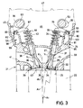
- the engine 21 includes a cylinder block which may be conventional and hence is only shown in phantom in Figure 3 in which a plurality of aligned bores 23 are formed.
- the engine 21 is of the four cylinder in line type. It should be readily apparent, however, to those skilled in the art how the invention can be practiced in conjunction with engines having other numbers of cylinders and other cylinder configurations.
- a cylinder head assembly indicated generally by the reference numeral 24 is affixed to the cylinder block 22 by means of a plurality of fasteners 25 that pass through appropriate openings in the cylinder head 24 and which are threaded into threaded openings in the cylinder block. It should be noted that the fasteners 25 are disposed so that they will be located at the four corners of the cylinder bores 23, as indicated by the broken circles in Figure 5, to show the relationship of these fasteners 25 to the cylinder bores 23.
- the lower face of the cylinder head 24 is provided with a plurality of recesses 26 which have a generally pent roof configuration, as will be described.
- Three intake valves comprised of a pair of center intake valves 27 and 28 and a side intake valve 29 are supported for reciprocation within the cylinder head 24 by respective valve guides 31. It will be noted that the intake valves 27, 28 and 29 are oriented so that the center intake valves 27 and 28 reciprocate along axes Y1 that are disposed at a relatively large acute angle ⁇ 2 to a plane A1 ( Figure 10) containing the cylinder bore axis X2 and extending parallel to the axis of rotation of the associated crankshaft.
- the side intake valve 29 reciprocates about an axis Y3 which is disposed at a lesser acute angle to this plane, this angle being indicated at ⁇ 1 in Figure 3.
- Each of the intake valves 27, 28 and 29 cooperates with a respective valve seat 32 pressed into the cylinder head 24 and defining an intake port at the termination of an intake passage 33 which extends through one side of the cylinder head.
- the intake passages 33 may be siamese so that one intake opening in the side of the cylinder head cooperates with each of the valve seats 32 or, alternatively, separate passages may be formed for each valve seat.
- the orientation of the heads of the valves 27, 28 and 29 gives the lower surface of the cylinder head cavity 26 a generally inclined portion 34 which extends across the plane A1 so that a portion of the heads of the valves 27 and 28 lies on the opposite side of this plane when the valves are closed, as clearly shown in Figure 10.
- Coil compression springs 34 encircle the stems of the valves 27, 28 and 29 and act against keeper retainer assemblies 35 for urging the valves 27, 28 and 29 to their closed positions.
- the mechanism for opening the intake valves 27, 28 and 29 will be described later.
- a pair of exhaust valves 36 and 37 are supported for reciprocation on the other side of the plane A1 by valve guides 38 which are pressed into the cylinder head assembly 24.
- the exhaust valves 36 and 37 reciprocate about respective axes Y2 which are disposed at an acute angle to the plane A1 which angle is less than the angle ⁇ 2 and greater than the angle ⁇ 1.
- the exhaust valves 36 and 37 cooperate with respective valve seats 39 that are pressed into the cylinder head 24 and which form the exhaust ports of exhaust passages 41 that extend through the side of the cylinder head 24 opposite to the intake side.
- the exhaust passages 41 may be separate or siamese. It should be noted that the disposition of the heads of the exhaust valves 36 and 37 gives rise to the combustion chamber cavity having a generally inclined surface 42 that intersects the surface 34 on the exhaust side of the plane A1 so that this intersection is slightly offset to the side of the combustion chamber.
- Coil compression springs 43 cooperate with keeper retainer assemblies 44 on the stems of the exhaust valves 36 and 37 for urging the exhaust valves 36 and 37 to their closed positions.
- the cylinder head 24 has an upstanding peripheral wall that defines an upwardly facing sealing surface 45 that defines in part a cavity 46 in which the valve actuating mechanism is contained.
- the cavity 46 is enclosed by means of a cam cover 47 that is affixed to the cylinder head 24 in a manner as will be described.
- On the intake side of the cylinder head 24 there is provided a plurality of bosses 48 which define generally semi cylindrical shaped bearing surfaces 49. Adjacent the bosses 48, there are provided further bosses 51 that define quarter cylindrical bearing surfaces 52.
- An intake camshaft indicated generally by the reference numeral 53 has spaced bearing surfaces 54 that are received within and journaled on the cylinder head bearing surfaces 49 and 52.
- the cylinder head 24 further has end bosses 55 that define further semi cylindrical bearing surfaces with which bearing portions 56 of the camshaft 53 cooperate so as to rotatably journal it.
- the cam cover 47 has a plurality of inwardly extending portions 58 that define semi cylindrical bearing surfaces 59 which cooperate with the camshaft bearing surfaces 54 and 56, respectively, so as to complete the journaling of the intake camshaft 53 in the cylinder head assembly.
- the exhaust side of the cylinder head assembly 24 also has a plurality of inwardly extending bosses 61 which have respective bearing surfaces 62 which are of a semi cylindrical configuration.
- An exhaust camshaft 63 is rotatably journaled on these bearing surfaces by means of bearing portions 64 formed integrally thereon.
- end walls 65 of the cylinder head 24 are provided with bearing surfaces 66 which cooperate with end bearing surfaces 67 on the exhaust camshaft 63 for its rotational support. It should be noted that the intake camshaft 53 and exhaust camshaft 63 rotate about parallel axes which are parallel to the axis of rotation of the associated crankshaft.
- bearing surfaces 68 Cooperating with the cylinder head bearing surfaces 62 and 66 are bearing surfaces 68 formed in inwardly extending portions 69 of the cam cover 47.
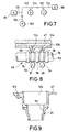
- the cam cover 47 is provided with a plurality of appropriately spaced bolt clearance holes 71 that are positioned in a pattern as best shown in Figure 6, and which receive bolts 72 that are threaded into tapped openings formed in the cylinder head 24 so as to secure the bearing caps formed by the cam cover 47 and the cam cover in place. Because of this construction, the head assembly may be made more compact than prior art arrangements and also the use of separate bearing caps for the camshaft may be avoided.
- a toothed sprocket 73 ( Figure 5) is affixed to one exposed end of the exhaust camshaft 63 and is driven by a toothed belt 74 in timed relationship with the engine crankshaft (not shown).
- a sprocket 75 At the opposite end of the exhaust camshaft 63, and within the cylinder head assembly 24, there is affixed a sprocket 75.
- a chain 76 encircles the sprocket 75 and drives a sprocket 77 that is affixed to the intake camshaft 53 at this end. In this way, the intake and exhaust camshafts will be driven in timed relationship from the engine output shaft.
- cam lobes 78 On the intake camshaft 53 for each cylinder.
- One of the cam lobes 78 is disposed between the bearing surfaces 49 and 52 and the camshaft bearing surfaces 54.
- the other of the cam lobes 78 are positioned outwardly of these bearing surfaces.
- Individual rocker arm assemblies 79 ( Figures 2 and 3) have an intermediate portion that is engaged by the cam lobe 78 and an end portion that is engaged with the stem of the respective intake valve 27, 28 and 29.
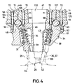
- the rocker arms 79 are pivotally supported by means of a hydraulically operated lash adjuster, indicated generally by the reference numeral 81 and having a construction as best shown in Figure 2.
- Each lash adjuster 81 comprises a cylindrical body portion 82 having an internal bore in which a tappet member 83 is slidably supported.
- the tappet member 83 has a hollow central portion 84 which communicates with a pressure chamber 85 positioned at the bottom of the adjuster body 82 through a passageway 86 in which a spring biased check valve 87 is positioned.
- Hydraulic pressure is delivered to the central interior 84 of the adjusting member from a delivery passage 88 formed in the body 82 and a delivery passage 89 formed in the tappet 83.
- the hydraulic pressure acts under the tappet 83 so as to hold the clearance in the system to zero clearance.
- a light compression spring 91 also acts to hold the tappet 83 in position when the engine is not running.
- a further passage 92 extends through the tappet 83 and communicates with a spherical socket 93 formed in the rocker arm 79 for lubrication.
- a delivery passage supplies oil to the lash adjuster 81 for the aforedescribed operation.
- the bores in which the adjusters 81 are positioned are indicated by the reference numeral 94 and are oriented as described in my aforenoted copending application. These bores terminate in lower shoulders 95 against which the adjuster bodies 82 react.
- the exhaust camshaft 63 is provided with pairs of cam lobes 96 that are disposed on opposite sides of their bearing portions 64 so as to operate the exhaust valves 36 and 37. These cam lobes 96 cooperate with intermediate portions of exhaust rocker arms 97 which have one end portion engaged with the stems of the valves 36 and 37 for operating them. The opposite ends of the rocker arms 97 cooperate with hydraulic lash adjusters 98 which have an internal construction the same as those associated with the intake valves (lash adjusters 81). For this reason, the description of the exhaust lash adjusters 98 is not believed to be necessary.
- adjusters 98 are received in bores 99 configured as described in my aforenoted copending application and which have their tappets 83 cooperating with spherical recesses 101 in the rocker arms 97.
- the base of the bores 99 is formed with a surface 102 against which the adjuster body reacts.
- the engine 21 is provided with a lubricating system that includes an oil reservoir which may be of either the wet or dry sump type and at least a pressure pump, indicated generally by the reference numeral 103 in Figures 1 and 7.
- the pump 103 is driven from the engine output shaft in a suitable manner and lubricates the crankshaft and components associated with the cylinder block in a well known manner.
- this lubrication system includes a passageway that extends through the cylinder block 22 and which cooperates with a main oil delivery passage 104 ( Figure 1) that extends upwardly through the lower face of the cylinder head 24 between a pair of cylinders thereof.
- the passageway 104 is, in the illustrated embodiment, on the intake side of the cylinder head 24 for a reason to be described.
- a cross drilled passageway 105 intersects the passage 104 and is closed by a closure plug 106.
- a further drilled passageway 107 extends down from the cylinder head sealing surface 45 through a side wall 108 of the cylinder head and intersects the passageway 105.
- a sleeve 109 is pressed into this passageway and cooperates with a corresponding passageway 111 formed in a side wall 112 of the cam cover 47.
- a cross drilled passageway 113 extends transversely across the cam cover 47 as shown in Figures 1 and 6, and intersects the passageway 111.
- This cross drilled passageway 113 is closed at its outer end by means of a closure plug 114.
- a further passageway 115 is drilled in the opposite wall 116 of the cam cover 47 and cooperates with a sleeve 117 that is pressed into a side wall 118 of the cylinder head 24 around a further oil passageway 119 which is likewise drilled in the cylinder head 24.
- the passageway 105 at the intake side of the cylinder head assembly is intersected by a transversely extending oil gallery 121 which intersects the bores 94 in which the lash adjusters 81 are slidably supported adjacent the delivery ports 88.
- a series flow oil delivery for supplying lubricant under pressure to the intake adjusters 81.
- a gallery 122 is drilled in the opposite wall 118 of the cylinder head and intersects the bores 99 in which the exhaust valve adjusters 98 are positioned. Since the intake oil gallery 121 is closer to the source of oil pressure, there is a greater likelihood that uniform pressure will be delivered to both the intake adjusters 81 and exhaust adjusters 98, bearing in mind the fact that there are more intake adjusters than exhaust adjusters, and thus the system will operate at a more uniform pressure.
- one or more oil drain passageways 128 are formed in the cylinder head 24 for draining lubricant back to the crankcase of the engine.
- Each combustion chamber of the engine is provided with a single spark plug for firing the charge therein.
- the cylinder head 24 is provided with a tapped opening 129 for receiving the spark plug. This tapped opening is formed at the base of the larger opening 131.
- the cam cover has an even larger opening 132 for accessing these spark plugs. This construction appears best in Figure 9.
Claims (14)
- Zylinderkopf-Schmierungssystem eines Verbrennungsmotors (21) mit einem Zylinderkopf (24) mit einer ersten Reihe hydraulischer Spieleinstellelemente (81) zur Betätigung von Einlaßventilen (27, 28, 29), einer zweiten Reihe hydraulischer Spieleinstellelemente (98) zur Betätigung von Auslaßventilen (36, 37), einer Ölpumpe (103), einer ersten Leitungseinrichtung (104, 121), die sich zu der ersten Reihe von Spieleinstellelementen (81) zur Schmierung der ersten Reihe von Spieleinstellelementen (81) erstreckt, einer zweiten Leitungseinrichtung (104, 122), die sich zu der zweiten Reihe von Spieleinstellelementen (98) zur Schmierung der zweiten Reihe von Spieleinstellelementen (98) erstreckt, einschließlich einer Einrichtung zur Verbindung der ersten und zweiten Leitungseinrichtungen (104, 121; 104, 122) mit der Ölpumpe (103), wobei die Länge der ersten Leitung (104, 121) von der Ölpumpe (103) zu der ersten Reihe von Spieleinstellelementen (81) der Einlaßventile (27, 28, 29) kürzer ist als die Länge der Leitung (104, 122) von der Ölpumpe (103) zu der zweiten Reihe von Spieleinstellelementen (98) der Auslaßventile (36, 37), dadurch gekennzeichnet, daß die Einlaßventile (27, 28, 29) eine größere Anzahl von Spieleinstellelementen (81) als die Auslaßventile (36, 37) aufweisen und daß ein Hauptölzufuhrkanal (104), der einen Teil der ersten Leitung (104, 121) bildet, sich nach oben außerhalb der Kopfbolzenbohrungen durch die untere Stirnfläche des Zylinderkopfes (24) erstreckt.
- Zylinderkopf-Schmierungssystem nach Anspruch 1, gekennzeichnet durch eine Nockenwelle (53, 63), die drehbar um zumindest ein Lager (49, 52; 62, 64) gelagert ist, wobei die Ölpumpe (103) und die ersten und zweiten Leitungseinrichtungen (104, 121, 122) Schmieröl unter Druck von der Ölpumpe (103) zu den Spieleinstellelementen (81, 98) und dem Lager (49, 52; 62, 64) zuführen.
- Zylinderkopf-Schmierungssystem nach Anspruch 1 oder 2, gekennzeichnet durch eine Mehrzahl von Nockenwellenlagern (49, 52; 62, 64).
- Zylinderkopf-Schmierungssystem nach zumindest einem der vorhergehenden Ansprüche 1-3, dadurch gekennzeichnet, daß die Nockenwellenlager (49, 52; 62, 64) und die Spieleinstellelemente (81, 98) in Reihe geschmiert werden.
- Zylinderkopfschmierungssystem nach zumindest einem der vorhergehenden Ansprüche 1-4, gekennzeichnet durch ein Paar Nockenwellen (53, 63), die jeweils einer Mehrzahl von Lagern (49, 52; 62, 64) und einer Mehrzahl von Spieleinstellelementen (81, 98) zugeordnet sind, wobei das Schmieröl zu den Nockenwellenlagern (49, 52; 62, 64) in einer seriellen Strömungsverbindung zugeführt wird, wobei das Schmieröl zu den Spieleinstellelementen (81, 98), die jeder der Nockenwellen (53, 63) zugeordnet sind, in einer parallelen Strömungsverbindung zugeführt wird und wobei die einzelnen Spieleinstellelemente (81, 98), die jeder Nockenwelle (53, 63) zugeordnet sind, in einer seriellen Strömungsverbindung geschmiert werden.
- Zylinderkopf-Schmierungssystem nach zumindest einem der vorhergehenden Ansprüche 1-5, dadurch gekennzeichnet, daß das Schmieröl den Schmiersystem benachbart zu der einen Nockenwelle (53) die der größeren Anzahl von Spieleinstellelementen (81) zugeordnet ist, zugeführt wird, um den Schmiermitteldruck an allen Spieleinstellelementen (81, 98) im wesentlichen gleich zu halten.
- Zylinderkopf-Schmierungssystem nach zumindest einem der vorhergehenden Ansprüche 1-6, dadurch gekennzeichnet, daß die Nockenwellen (53, 63) in einer Vertiefung, die durch einen Zylinderkopf gebildet ist, gelagert sind und wobei die Vertiefung (46) durch einen Nockendeckel (47) geschlossen ist, wobei zumindest ein Abschnitt der Schmieröl-Leitungseinrichtung (104, 121, 122) in dem Nockendeckel (47) ausgebildet ist.
- Zylinderkopf-Schmierungssystem nach zumindest einem der vorhergehenden Ansprüche 1-7, dadurch gekennzeichnet, daß die Nockenwellenlager (49, 52; 62, 64) teilweise durch den Nockendeckel (47) gebildet sind und die Leitungseinrichtung, die das Schmieröl zu den Nockenwellenlagern zuführt, in dem Nockendeckel (47) ausgebildet ist.
- Zylinderkopf-Schmierungssystem nach zumindest einem der vorhergehenden Ansprüche 1-8, dadurch gekennzeichnet, daß die Schmiermittelleitungen zur Versorgung der Spieleinstellelemente (81, 98) in dem Zylinderkopf (24) ausgebildet sind und daß der Zylinderkopf (24) Kanäle (106, 107) aufweist, die mit dem Nockendeckel (47) verbunden sind, um die Nockendeckel-Schmiermittelkanäle (111, 113) mit den Zylinderkopf-Schmiermittelkanälen (106, 107) zu verbinden, während die Ölpumpe (103) das Schmieröl dem Motor durch den Zylinderkopf (24) zuführt.
- Zylinderkopf-Schmierungssystem nach zumindest einem der vorhergehenden Ansprüche 1-8, dadurch gekennzeichnet, daß drei Spieleinstellelemente (81) je Zylinder, die einer ersten Nockenwelle (53) zugeordnet sind, und zwei Spieleinstellelemente (98) je Zylinder, die der zweiten Nockenwelle (63) zugeordnet sind, vorgesehen sind.
- Zylinderkopf-Schmierungssystem nach zumindest einem der vorhergehenden Ansprüche 1-10, dadurch gekennzeichnet, daß eine Mehrzal von Zylindern, die dem Zylinderkopf zugeordnet sind, vorgesehen sind.
- Zylinderkopf-Schmierungssystem nach zumindest einem der vorhergehenden Ansprüche 1-11, dadurch gekennzeichnet, daß die ersten und zweiten Leitungseinrichtungen (104, 121, 122) in dem Zylinderkopf ausgebildet sind.
- Zylinderkopf-Schmierungssystem nach Anspruch 12, dadurch gekennzeichnet, daß zumindest ein Abschnitt einer dritten Leitungseinrichtung (124, 125) in einem Nockendeckel (47) ausgebildet ist, der eine in dem Zylinderkopf ausgebildete Vertiefung schließt, in der die Nockenwellen (53, 63) gelagert sind.
- Zylinderkopf-Schmierungssystem nach Anspruch 13, dadurch gekennzeichnet, daß die Lager (58) zumindest teilweise durch den Nockendeckel (47) ausgebildet sind und die dritte Leitungseinrichtung (124, 125) in jeder der Nockendeckel-Lageroberflächen (58) endet.
Priority Applications (1)
| Application Number | Priority Date | Filing Date | Title |
|---|---|---|---|
| EP95101503A EP0654589B1 (de) | 1989-07-14 | 1990-07-13 | Zylinderkopfschmierungsanlage für eine Brennkraftmaschine |
Applications Claiming Priority (2)
| Application Number | Priority Date | Filing Date | Title |
|---|---|---|---|
| JP1181893A JP2829866B2 (ja) | 1989-07-14 | 1989-07-14 | 4サイクルエンジンの潤滑装置 |
| JP181893/89 | 1989-07-14 |
Related Child Applications (2)
| Application Number | Title | Priority Date | Filing Date |
|---|---|---|---|
| EP95101503A Division-Into EP0654589B1 (de) | 1989-07-14 | 1990-07-13 | Zylinderkopfschmierungsanlage für eine Brennkraftmaschine |
| EP95101503.1 Division-Into | 1995-02-03 |
Publications (2)
| Publication Number | Publication Date |
|---|---|
| EP0408081A1 EP0408081A1 (de) | 1991-01-16 |
| EP0408081B1 true EP0408081B1 (de) | 1995-12-13 |
Family
ID=16108730
Family Applications (2)
| Application Number | Title | Priority Date | Filing Date |
|---|---|---|---|
| EP19900113491 Expired - Lifetime EP0408081B1 (de) | 1989-07-14 | 1990-07-13 | Zylinderkopf-Schmiersystem einer Brennkraftmaschine |
| EP95101503A Expired - Lifetime EP0654589B1 (de) | 1989-07-14 | 1990-07-13 | Zylinderkopfschmierungsanlage für eine Brennkraftmaschine |
Family Applications After (1)
| Application Number | Title | Priority Date | Filing Date |
|---|---|---|---|
| EP95101503A Expired - Lifetime EP0654589B1 (de) | 1989-07-14 | 1990-07-13 | Zylinderkopfschmierungsanlage für eine Brennkraftmaschine |
Country Status (3)
| Country | Link |
|---|---|
| EP (2) | EP0408081B1 (de) |
| JP (1) | JP2829866B2 (de) |
| DE (2) | DE69031806T2 (de) |
Families Citing this family (12)
| Publication number | Priority date | Publication date | Assignee | Title |
|---|---|---|---|---|
| DE69414557T2 (de) * | 1994-06-15 | 1999-04-01 | Yamaha Motor Co Ltd | Zylinderkopfanordnung für eine Mehrventil-Brennkraftmaschine mit obenliegender Nockenwelle |
| JP3608325B2 (ja) * | 1997-01-21 | 2005-01-12 | いすゞ自動車株式会社 | Dohcエンジンの動弁装置 |
| DE19729948A1 (de) * | 1997-07-12 | 1999-01-14 | Deutz Ag | Nockenwellenlagerrahmen |
| EP1006272B1 (de) * | 1998-12-01 | 2007-04-11 | Honda Giken Kogyo Kabushiki Kaisha | Mehrzylinderkopf |
| JP2003193818A (ja) * | 2001-12-21 | 2003-07-09 | Aichi Mach Ind Co Ltd | カムシャフト軸受部へのオイル供給構造 |
| JP4723453B2 (ja) * | 2006-10-17 | 2011-07-13 | 川崎重工業株式会社 | エンジンおよび自動二輪車 |
| JP5078313B2 (ja) * | 2006-10-17 | 2012-11-21 | 川崎重工業株式会社 | 自動二輪車 |
| JP6213200B2 (ja) * | 2013-12-09 | 2017-10-18 | 三菱自動車工業株式会社 | エンジンのカムキャップ |
| JP2017048707A (ja) * | 2015-09-01 | 2017-03-09 | いすゞ自動車株式会社 | シリンダヘッドカバーの位置決め構造 |
| CN109707526B (zh) * | 2018-12-26 | 2021-12-14 | 濉溪泰高科技有限公司 | 一种定位点火的新能源汽车发动机缸盖 |
| DE102019000489A1 (de) * | 2019-01-23 | 2020-07-23 | Deutz Aktiengesellschaft | Ölversorgung |
| JP7322514B2 (ja) * | 2019-05-28 | 2023-08-08 | マツダ株式会社 | シリンダヘッド |
Family Cites Families (11)
| Publication number | Priority date | Publication date | Assignee | Title |
|---|---|---|---|---|
| JPS6079141A (ja) * | 1983-10-04 | 1985-05-04 | Honda Motor Co Ltd | Dohc型4サイクル内燃機関のシリンダヘツド |
| JPS61261612A (ja) * | 1985-05-14 | 1986-11-19 | Honda Motor Co Ltd | 内燃機関の油圧タペツト付動弁機構における給油装置 |
| JPS61261613A (ja) * | 1985-05-15 | 1986-11-19 | Honda Motor Co Ltd | 多気筒内燃機関の油圧タペツト付動弁機構における給油装置 |
| CA1328589C (en) * | 1985-08-21 | 1994-04-19 | Honda Giken Kogyo Kabushiki Kaisha (Also Trading As Honda Motor Co., Ltd .) | Oil supply system for a valve operating mechanism in internal combustion engines |
| JPH0622092Y2 (ja) * | 1987-04-29 | 1994-06-08 | スズキ株式会社 | 内燃機関のオイル通路 |
| DE3743854A1 (de) * | 1987-12-23 | 1989-07-06 | Michael Stirm | Vierventilsteuerung mit oberen abstuetzelementen |
| JPH088287Y2 (ja) * | 1988-02-22 | 1996-03-06 | 日産自動車株式会社 | Dohc4バルブ型内燃機関のシリンダヘッド |
| JPH087043Y2 (ja) * | 1988-10-29 | 1996-02-28 | 富士重工業株式会社 | ダブルオーバヘッドカム型動弁機構の潤滑装置 |
| EP0408080B1 (de) * | 1989-07-13 | 1995-02-08 | Yamaha Hatsudoki Kabushiki Kaisha | Ventil und Federanordnung für Brennkraftmaschine |
| JP2799190B2 (ja) * | 1989-07-14 | 1998-09-17 | ヤマハ発動機株式会社 | 4サイクルエンジンの動弁装置 |
| EP0420139B1 (de) * | 1989-09-28 | 1996-02-14 | Mazda Motor Corporation | Mehrventil-Brennkraftmaschine |
-
1989
- 1989-07-14 JP JP1181893A patent/JP2829866B2/ja not_active Expired - Fee Related
-
1990
- 1990-07-13 DE DE1990631806 patent/DE69031806T2/de not_active Expired - Fee Related
- 1990-07-13 EP EP19900113491 patent/EP0408081B1/de not_active Expired - Lifetime
- 1990-07-13 DE DE1990624117 patent/DE69024117T2/de not_active Expired - Fee Related
- 1990-07-13 EP EP95101503A patent/EP0654589B1/de not_active Expired - Lifetime
Also Published As
| Publication number | Publication date |
|---|---|
| DE69024117D1 (de) | 1996-01-25 |
| EP0654589A2 (de) | 1995-05-24 |
| EP0654589B1 (de) | 1997-12-10 |
| DE69031806T2 (de) | 1998-05-07 |
| EP0408081A1 (de) | 1991-01-16 |
| JPH0347417A (ja) | 1991-02-28 |
| DE69031806D1 (de) | 1998-01-22 |
| DE69024117T2 (de) | 1996-05-09 |
| EP0654589A3 (de) | 1995-06-28 |
| JP2829866B2 (ja) | 1998-12-02 |
Similar Documents
| Publication | Publication Date | Title |
|---|---|---|
| US5161495A (en) | Lubrication arrangement for engine | |
| US5954019A (en) | Variable valve timing arrangement for engine | |
| US4621597A (en) | Cylinder head for double overhead cam engine | |
| CA1328589C (en) | Oil supply system for a valve operating mechanism in internal combustion engines | |
| US4624222A (en) | Intake valve structure for internal combustion engine | |
| US6289861B1 (en) | Control for variable valve timing | |
| EP0408081B1 (de) | Zylinderkopf-Schmiersystem einer Brennkraftmaschine | |
| US5016592A (en) | Cylinder head and valve train arrangement for multiple valve engine | |
| US5347964A (en) | Valve train for internal combustion engines | |
| US6173689B1 (en) | Lubrication arrangement for engine valve actuation | |
| USRE35382E (en) | Lubrication arrangement for engine | |
| US6467166B1 (en) | Method of forming a camshaft for an engine | |
| US5099812A (en) | Cylinder head for internal combustion engine | |
| US5704330A (en) | Cylinder head arrangement for internal combustion engine | |
| US5125374A (en) | Valve actuating arrangement for engine | |
| US4649874A (en) | Oil supply system for valves in an internal combustion engine | |
| US4649873A (en) | Oil return system for overhead cam engine | |
| US5398649A (en) | S.O.H.C. five valve engine | |
| US5121718A (en) | Valve and spring arrangement for engine | |
| US5018497A (en) | Multiple valve internal combustion engine | |
| US5522354A (en) | Valve mechanism for internal combustion engine | |
| US4991549A (en) | Camshaft lubricating system for engine | |
| US5906186A (en) | Cylinder head for tappet arrangement for multi-valve engine | |
| EP0377829B2 (de) | Nockenwellenschmierungsanlage für Brennkraftmaschinen | |
| EP0608557B1 (de) | Brennkraftmaschine |
Legal Events
| Date | Code | Title | Description |
|---|---|---|---|
| PUAI | Public reference made under article 153(3) epc to a published international application that has entered the european phase |
Free format text: ORIGINAL CODE: 0009012 |
|
| AK | Designated contracting states |
Kind code of ref document: A1 Designated state(s): DE FR GB IT |
|
| 17P | Request for examination filed |
Effective date: 19901224 |
|
| 17Q | First examination report despatched |
Effective date: 19910920 |
|
| GRAA | (expected) grant |
Free format text: ORIGINAL CODE: 0009210 |
|
| AK | Designated contracting states |
Kind code of ref document: B1 Designated state(s): DE FR GB IT |
|
| XX | Miscellaneous (additional remarks) |
Free format text: TEILANMELDUNG 95101503.1 EINGEREICHT AM 03/02/95. |
|
| ITF | It: translation for a ep patent filed |
Owner name: PROPRIA PROTEZIONE PROPR. IND. |
|
| REF | Corresponds to: |
Ref document number: 69024117 Country of ref document: DE Date of ref document: 19960125 |
|
| ET | Fr: translation filed | ||
| PLBE | No opposition filed within time limit |
Free format text: ORIGINAL CODE: 0009261 |
|
| STAA | Information on the status of an ep patent application or granted ep patent |
Free format text: STATUS: NO OPPOSITION FILED WITHIN TIME LIMIT |
|
| 26N | No opposition filed | ||
| PGFP | Annual fee paid to national office [announced via postgrant information from national office to epo] |
Ref country code: DE Payment date: 20010709 Year of fee payment: 12 |
|
| PGFP | Annual fee paid to national office [announced via postgrant information from national office to epo] |
Ref country code: GB Payment date: 20010711 Year of fee payment: 12 |
|
| PGFP | Annual fee paid to national office [announced via postgrant information from national office to epo] |
Ref country code: FR Payment date: 20010712 Year of fee payment: 12 |
|
| REG | Reference to a national code |
Ref country code: GB Ref legal event code: IF02 |
|
| PG25 | Lapsed in a contracting state [announced via postgrant information from national office to epo] |
Ref country code: GB Free format text: LAPSE BECAUSE OF NON-PAYMENT OF DUE FEES Effective date: 20020713 |
|
| PG25 | Lapsed in a contracting state [announced via postgrant information from national office to epo] |
Ref country code: DE Free format text: LAPSE BECAUSE OF NON-PAYMENT OF DUE FEES Effective date: 20030201 |
|
| GBPC | Gb: european patent ceased through non-payment of renewal fee |
Effective date: 20020713 |
|
| PG25 | Lapsed in a contracting state [announced via postgrant information from national office to epo] |
Ref country code: FR Free format text: LAPSE BECAUSE OF NON-PAYMENT OF DUE FEES Effective date: 20030331 |
|
| REG | Reference to a national code |
Ref country code: FR Ref legal event code: ST |
|
| PG25 | Lapsed in a contracting state [announced via postgrant information from national office to epo] |
Ref country code: IT Free format text: LAPSE BECAUSE OF NON-PAYMENT OF DUE FEES Effective date: 20050713 |