EP0406499A1 - Leuchtstoffkolben mit rohrförmigem Sockel und umgekehrten Elektroden - Google Patents
Leuchtstoffkolben mit rohrförmigem Sockel und umgekehrten Elektroden Download PDFInfo
- Publication number
- EP0406499A1 EP0406499A1 EP89401937A EP89401937A EP0406499A1 EP 0406499 A1 EP0406499 A1 EP 0406499A1 EP 89401937 A EP89401937 A EP 89401937A EP 89401937 A EP89401937 A EP 89401937A EP 0406499 A1 EP0406499 A1 EP 0406499A1
- Authority
- EP
- European Patent Office
- Prior art keywords
- electrodes
- foot
- tube
- bulb according
- stage
- Prior art date
- Legal status (The legal status is an assumption and is not a legal conclusion. Google has not performed a legal analysis and makes no representation as to the accuracy of the status listed.)
- Withdrawn
Links
- 238000003466 welding Methods 0.000 claims abstract description 17
- 238000007789 sealing Methods 0.000 claims abstract description 14
- QSHDDOUJBYECFT-UHFFFAOYSA-N mercury Chemical compound [Hg] QSHDDOUJBYECFT-UHFFFAOYSA-N 0.000 claims description 33
- 229910052753 mercury Inorganic materials 0.000 claims description 28
- 239000003708 ampul Substances 0.000 claims description 3
- 239000003610 charcoal Substances 0.000 claims description 3
- 239000006060 molten glass Substances 0.000 claims description 3
- 238000010276 construction Methods 0.000 abstract 2
- 238000007599 discharging Methods 0.000 abstract 1
- 239000011521 glass Substances 0.000 description 13
- 210000000078 claw Anatomy 0.000 description 8
- 238000004519 manufacturing process Methods 0.000 description 6
- 238000000034 method Methods 0.000 description 6
- OKTJSMMVPCPJKN-UHFFFAOYSA-N Carbon Chemical compound [C] OKTJSMMVPCPJKN-UHFFFAOYSA-N 0.000 description 5
- 239000002775 capsule Substances 0.000 description 5
- XKRFYHLGVUSROY-UHFFFAOYSA-N Argon Chemical compound [Ar] XKRFYHLGVUSROY-UHFFFAOYSA-N 0.000 description 4
- 238000000429 assembly Methods 0.000 description 4
- 230000000712 assembly Effects 0.000 description 4
- 230000004807 localization Effects 0.000 description 4
- 239000000843 powder Substances 0.000 description 4
- 230000008901 benefit Effects 0.000 description 3
- 229910052799 carbon Inorganic materials 0.000 description 3
- 230000005684 electric field Effects 0.000 description 3
- 229910052751 metal Inorganic materials 0.000 description 3
- 239000002184 metal Substances 0.000 description 3
- 238000002360 preparation method Methods 0.000 description 3
- 238000000638 solvent extraction Methods 0.000 description 3
- 229910052786 argon Inorganic materials 0.000 description 2
- 230000006835 compression Effects 0.000 description 2
- 238000007906 compression Methods 0.000 description 2
- 238000009833 condensation Methods 0.000 description 2
- 230000005494 condensation Effects 0.000 description 2
- 238000009826 distribution Methods 0.000 description 2
- 230000004927 fusion Effects 0.000 description 2
- 230000006872 improvement Effects 0.000 description 2
- 238000012423 maintenance Methods 0.000 description 2
- 239000000203 mixture Substances 0.000 description 2
- 230000002093 peripheral effect Effects 0.000 description 2
- 230000009467 reduction Effects 0.000 description 2
- 230000002441 reversible effect Effects 0.000 description 2
- 230000008719 thickening Effects 0.000 description 2
- 229910000863 Ferronickel Inorganic materials 0.000 description 1
- 101001050607 Homo sapiens KH domain-containing, RNA-binding, signal transduction-associated protein 3 Proteins 0.000 description 1
- 102100023428 KH domain-containing, RNA-binding, signal transduction-associated protein 3 Human genes 0.000 description 1
- PXHVJJICTQNCMI-UHFFFAOYSA-N Nickel Chemical compound [Ni] PXHVJJICTQNCMI-UHFFFAOYSA-N 0.000 description 1
- 230000006978 adaptation Effects 0.000 description 1
- 238000004873 anchoring Methods 0.000 description 1
- 238000000137 annealing Methods 0.000 description 1
- 239000011230 binding agent Substances 0.000 description 1
- 238000006555 catalytic reaction Methods 0.000 description 1
- 238000011109 contamination Methods 0.000 description 1
- 230000007547 defect Effects 0.000 description 1
- 238000007872 degassing Methods 0.000 description 1
- 238000011161 development Methods 0.000 description 1
- 238000001035 drying Methods 0.000 description 1
- 238000004870 electrical engineering Methods 0.000 description 1
- 238000013213 extrapolation Methods 0.000 description 1
- 230000004907 flux Effects 0.000 description 1
- 230000002070 germicidal effect Effects 0.000 description 1
- 238000007511 glassblowing Methods 0.000 description 1
- 239000003292 glue Substances 0.000 description 1
- 239000010439 graphite Substances 0.000 description 1
- 229910002804 graphite Inorganic materials 0.000 description 1
- 229910052738 indium Inorganic materials 0.000 description 1
- APFVFJFRJDLVQX-UHFFFAOYSA-N indium atom Chemical compound [In] APFVFJFRJDLVQX-UHFFFAOYSA-N 0.000 description 1
- 238000009776 industrial production Methods 0.000 description 1
- 229910052500 inorganic mineral Inorganic materials 0.000 description 1
- 238000011835 investigation Methods 0.000 description 1
- 238000003754 machining Methods 0.000 description 1
- 239000000463 material Substances 0.000 description 1
- 239000000155 melt Substances 0.000 description 1
- 230000008018 melting Effects 0.000 description 1
- 238000002844 melting Methods 0.000 description 1
- 230000005499 meniscus Effects 0.000 description 1
- 229910044991 metal oxide Inorganic materials 0.000 description 1
- 150000004706 metal oxides Chemical class 0.000 description 1
- 239000011707 mineral Substances 0.000 description 1
- 230000008569 process Effects 0.000 description 1
- 238000005086 pumping Methods 0.000 description 1
- 238000011084 recovery Methods 0.000 description 1
- 238000011160 research Methods 0.000 description 1
- 230000000717 retained effect Effects 0.000 description 1
- 238000007711 solidification Methods 0.000 description 1
- 230000008023 solidification Effects 0.000 description 1
- 238000012360 testing method Methods 0.000 description 1
- 238000011144 upstream manufacturing Methods 0.000 description 1
- 238000005493 welding type Methods 0.000 description 1
Images


Classifications
-
- H—ELECTRICITY
- H01—ELECTRIC ELEMENTS
- H01J—ELECTRIC DISCHARGE TUBES OR DISCHARGE LAMPS
- H01J9/00—Apparatus or processes specially adapted for the manufacture, installation, removal, maintenance of electric discharge tubes, discharge lamps, or parts thereof; Recovery of material from discharge tubes or lamps
- H01J9/24—Manufacture or joining of vessels, leading-in conductors or bases
- H01J9/32—Sealing leading-in conductors
- H01J9/323—Sealing leading-in conductors into a discharge lamp or a gas-filled discharge device
-
- H—ELECTRICITY
- H01—ELECTRIC ELEMENTS
- H01J—ELECTRIC DISCHARGE TUBES OR DISCHARGE LAMPS
- H01J61/00—Gas-discharge or vapour-discharge lamps
- H01J61/02—Details
- H01J61/36—Seals between parts of vessels; Seals for leading-in conductors; Leading-in conductors
- H01J61/366—Seals for leading-in conductors
Definitions
- the present invention relates to the production of a fluorescent bulb with a standard base with a tubular base carrying two stages of opposite, reversed electrodes, and with rapid ignition by localization of mercury in the discharge plasma.
- the invention relates to the field of fluorescent or luminescent lighting, for general use, wherever such a bulb can replace an incandescent bulb, but also by the mode of operation with mercurial plasma, have other applications not -limits, such as, for example, tanning, inactinics, some ultra-violet and germicide.
- the lamp according to the invention contains, in its standardized base, its supply assembly formed by a capacitive ballast and an electronic ignition system.
- fluorescent bulbs of all shapes are known, spherical, cylindrical, conical, but much less numerous where the electrodes are placed on glass rods to locate the discharge filaments. These rods then forming the base of the lamp.
- the electrodes are placed at certain points of the rods including different assemblies, procedures and achievements, or attempts to lead to industrially exploitable assemblies.
- This type of bulb is also not equipped with any base, not even standardized.
- French patent N ° 87-08486 presents and describes a new tubular foot making it possible to permanently produce a foot that meets all expectations and satisfies many criteria specific to a fluorescent or luminescent bulb.
- This foot has the considerable advantage of being able to weld the electrodes of the bottom of the foot, or first stage, in a peripheral manner, sandwiched between two tubes, with normal positioning of a rod without causing any intermediate partitioning between the two stages of electrodes. , which is not the case for the other patents cited upstream.
- this latter patent has a defect when obtaining discharge plasma from one end to the other of the envelope, over the entire length of the latter, by the very position of the first stage electrodes.
- Aesthetic because beyond the discharge zone of the first stage of electrodes, this part therefore between the filament and the collar is not activated by the electric field generating mercurial ultraviolet, and provides increasing opacity on 4 to 8 centimeters.
- the type of welding relating to the bottom of the foot electrodes therefore imposes constraints, such as fixed and defined mounting, giving a non-reversible and reusable weld, by the direction and the orientation of the foot electrodes, in the same sense as those on the second floor.
- none of these lamps or bulbs have a mercury reservoir or capsule on the discharge path.
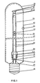
- the embodiment of the bulb according to the invention and of its base (1) carrying electrodes (4,5) consists in that the first stage electrodes of the tubular base (25) are mounted in opposition or inverted with respect to the second stage electrodes (17,18), that is to say that said electrodes are arranged in opposite directions, two by two by their hook (10,12).
- Electrodes are then covered over approximately 1 cm by the support tube of the second stage of electrodes, or central tube (7).
- the electrodes are therefore sandwiched (13) between the foot tube and the central tube, which consequently encloses them, contains them, fits them (14) along the foot tube, giving them orientation final outlet, along the foot tube, towards the flare or the flange (2).
- the latter has undergone a flaring operation (11), cylindrical widening, allowing it to partially cover the said electrodes, and a portion of the foot tube sufficient to carry out the sandwich, or crown welding operation of these electrodes.
- This cylindrical flare can end with a cone trunk (20).
- This actual welding operation is carried out using a blowtorch, the parts of the tube to be welded being held by their ends in the jaws of a rotating lathe, and or at least one external knurl forces the two thicknesses of glass to be applied. between them, and grab the two electrodes, a punch or sliding charcoal (16) or other is advanced in the bottom of the tube to the level of the current weld (15) in order to contain the molten glass of a part, and the force of the tool on the other hand, which can come by deformation to obstruct this tubular part, this forming the subsequent passage of the current supply wires to the electrodes (22,24), see the passage d '' a rod (30) in a different location (Fig. 4 and 5), but also weaken the solidity of the self-supporting weld (3) of the second stage rod, carrying the second pair of electrode and other operating elements of the lamp.
- the current supply wires from the first stage of electrodes are therefore pulled and blocked in the second stage rod, to allow the passage of the punch or charcoal (graphite) for maintaining the internal diametrical base of the foot.
- the socket (9) with a diameter of 4 and a length of 100 mm is immediately mounted in order to reduce the risk of breakage due to thermal difference.
- the current supply wires to the bottom of the electrodes themselves oriented towards the flange by their sandwich sealing position, are turned over, bent (44) after this welding, and introduced towards the bottom of the foot to join the flare and the flange or they will be subsequently and definitively connected.
- Another method of diametric maintenance (27) consists of the use of centrifugal force and an external containment mold.
- the sealed electrodes form the glass passages (6), and the sealing operation always takes place at one time.
- the sealing (15) of these two electrodes oriented towards the flare and diametrically opposite or not, takes place in the space of a double concentric ring, the external concentric ring being formed by the support tube of the second stage of electrodes (7), the internal crown being represented by the tubular wall of the foot tube, the weld is therefore of the peripheral type in a crown and in a sandwich.
- the latter carries at its upper end a preparation consisting of thickening (31) and increasing its outside diameter at the level of the crown, in order to reduce the risk of sticking of the electrodes to the wall during their sealing (15).
- the latter during this operation are folded outward, away from the wall formed by the bottom of the tube.
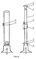
- the said bottom tube can be of a much larger diameter (32) passing from 10 to 18 mm and more in order to receive and carry the rod (9) as close as possible to the collar (2).
- This tube section is therefore flared, then undergoes a constriction operation (33) to be at the side of the enlargement (11) of the central support tube.
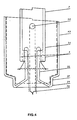
- Another variant consists in that the central tube does not undergo cylindrical flaring, but is kept as such (34) as a support tube for the second stage of electrodes (FIGS. 4 and 6).
- the rod can be placed on the wall of the second stage support tube (30), above the sandwich weld.
- this embodiment of sandwiching of the first stage electrodes has the following advantages, - routing of the current supply wires without envrage thanks to the absence of partitioning between the first and the second stage of electrodes - sealing of the foot electrodes and welding of the central support rod in a single operation - normal positioning of the pump pipe - sealing of the second stage electrodes without any constraint - virtually unlimited extension of the central support rod of the second stage of electrodes.
- Said electrodes are held in a small clamp with fixed dimensions, respecting the spacing and the depth of the glass-metal grip of these electrodes.
- the glass is heated, melted, then flattened with forceps, sending the passages. A little air can be sent through the collar, so as to slightly expand the part of the crushed glass.
- These electrodes are mounted in the exact plane position of the first stage electrodes.
- the four electrodes are mounted in the same plane, two by two, in two working steps, their hooks (10,12) being opposite two by two.
- the hooks of the bottom of the electrodes being oriented towards the flange (2), the hooks of the top of the support rod electrodes, being oriented towards the round bottom (36) forming the end of the envelope (37)
- the two filaments (19, 21) are therefore located in the same plane but separated opposite by the welding in crown and enlargement bulb, flare (11) of the central tube on the weight tube.
- the filament at the bottom of the foot is slightly off-center because of the circumference of the stem (1) at the bottom of the foot.
- the foot electrodes can also be slightly offset, so that the filament can be kept horizontally and in the same plane as that of the second stage, to avoid kinking of the plasma in discharge regime.
- This filament can be separated from the bottom of the foot rod by the addition of at least one fine nickel wire taken, or glued in the bottom of the foot weld, keeping it a few millimeters from this rod, towards the flared part. .
- the four electrodes according to the invention all have their current supply wire, during their assembly, notably that of the end of the foot, the wires of which descend along the central support rod, towards the flared part.
- the support foot of the four electrodes may include a resistive track of 20 to 40,000 Ohms (35) acting as an auxiliary electrode for quick start, self-ignition style, and connecting each pair of 'electrode to each other, so as to short circuit and trigger the plasma.
- the electronic ignition system is absent.
- the preparation of the envelope, of various shape, the envelopes forming the discharge vessel, are according to the invention tubular cylindrical, and have a diameter varying from 32 to 68 millimeters.
- the envelopes are then coated internally with fluorescent paste (23), then pyrolized and prepared for mounting the complete stand.
- the welding (29) of the complete foot on the envelope is carried out using specialized machines.
- the foot Before mounting, the foot is provided with two filaments and in the middle, either on the central support rod, a small mercury tank (28) suitable for triggering the plasma.
- a small mercury tank (28) suitable for triggering the plasma.
- the ends of this reservoir at least one, being each oriented towards a filament.
- the bulb is then placed on a pumping frame, emptied, filled with argon, then the queusot is sealed.
- the inter-filament distance can be extrapolated by the use of different lengths of support rod, specific to the second electrode stage.
- the length of the rod and the inter-filament distance increases from 12 to 48 centimeters, the power passing from 6 to 60 Watt.
- the length of the envelope varies (41) in the same proportions, the quantity of emissive powder surface and the power required to activate it.
- This principle of realization of the bulb is applicable to other discharge tubes, provided with various caps, and not containing ballast.
- the bulb can be detachable from its base, making it possible to recover its ballast when it has become unusable.
- mercury treated with indium to lower its melting point, encapsulated in the discharge vessel; the meniscus surface tension being greater than the weight of mercury and relative to the diameter of the capsule, the mercury (surplus) remaining in more than 60 percent in said capsule, the mercury plasma as soon as it stops tends to recombine, to recondense, with the mercury of the said capsule.
- the present invention aims to solve these difficulties and provide a solution to the problems of ignition and operation of fluorescent bulbs.
- the present invention therefore relates to a significant improvement in the ignition of the discharge plasma of fluorescent bulbs, with a single foot carrying two stages of electrodes.
- One solution may consist in the fact that the mercury can be located in the queusot, but this does not guarantee its good distribution in the enclosure, in particular when the queusot emerges behind the filament, or even in the immediate vicinity, at the bottom of the foot, by imbalance of the mercurial cloud.
- the mercury is encapsulated in a straight or curved glass tube, or of different shapes, glass of the capillary type or other, with a diameter of 2 to 6 millimeters, delivered from canes of 1.50 meters , in 1 cm sections.
- said tanks are straight with a diameter of 4 mm and a thickness of 0.7 mm (45).
- test tubes can also have the form of small test tubes (49), that is to say closed at one end (50).
- claws are double-grip, for holding the reservoir, and of the latter on the foot stem (7).
- Each tank therefore has its own holding and fixing claw.
- the tanks thus provided with their claw are filled with mercury (28), using a syringe or other method, for a quantity varying from 1 to 20 milligrams, 6 according to the invention
- said reservoir (45) of mercury is continuously and permanently in the thermoelectro-ionic flux, equidistant from each thermo-emissive assembly, in the axis which best corresponds to the plasma, and having at minus an opening facing a filament (49).
Landscapes
- Engineering & Computer Science (AREA)
- Manufacturing & Machinery (AREA)
- Vessels And Coating Films For Discharge Lamps (AREA)
Priority Applications (1)
| Application Number | Priority Date | Filing Date | Title |
|---|---|---|---|
| EP89401937A EP0406499A1 (de) | 1989-07-06 | 1989-07-06 | Leuchtstoffkolben mit rohrförmigem Sockel und umgekehrten Elektroden |
Applications Claiming Priority (1)
| Application Number | Priority Date | Filing Date | Title |
|---|---|---|---|
| EP89401937A EP0406499A1 (de) | 1989-07-06 | 1989-07-06 | Leuchtstoffkolben mit rohrförmigem Sockel und umgekehrten Elektroden |
Publications (1)
| Publication Number | Publication Date |
|---|---|
| EP0406499A1 true EP0406499A1 (de) | 1991-01-09 |
Family
ID=8202972
Family Applications (1)
| Application Number | Title | Priority Date | Filing Date |
|---|---|---|---|
| EP89401937A Withdrawn EP0406499A1 (de) | 1989-07-06 | 1989-07-06 | Leuchtstoffkolben mit rohrförmigem Sockel und umgekehrten Elektroden |
Country Status (1)
| Country | Link |
|---|---|
| EP (1) | EP0406499A1 (de) |
Citations (4)
| Publication number | Priority date | Publication date | Assignee | Title |
|---|---|---|---|---|
| GB634443A (en) * | 1946-11-25 | 1950-03-22 | Gen Electric Co Ltd | Improvements in and relating to seals for electric discharge devices |
| JPS55155461A (en) * | 1979-05-22 | 1980-12-03 | Toshiba Corp | Semibase type low pressure mercury vapour discharge lamp |
| JPS57162240A (en) * | 1981-03-28 | 1982-10-06 | Nec Home Electronics Ltd | Manufacture of circular fluorescent lamp |
| FR2575600A1 (fr) * | 1984-12-31 | 1986-07-04 | Dumas Pierre | Ampoule fluorescente a un culot a contact a emission longitudinale directe sur pied |
-
1989
- 1989-07-06 EP EP89401937A patent/EP0406499A1/de not_active Withdrawn
Patent Citations (4)
| Publication number | Priority date | Publication date | Assignee | Title |
|---|---|---|---|---|
| GB634443A (en) * | 1946-11-25 | 1950-03-22 | Gen Electric Co Ltd | Improvements in and relating to seals for electric discharge devices |
| JPS55155461A (en) * | 1979-05-22 | 1980-12-03 | Toshiba Corp | Semibase type low pressure mercury vapour discharge lamp |
| JPS57162240A (en) * | 1981-03-28 | 1982-10-06 | Nec Home Electronics Ltd | Manufacture of circular fluorescent lamp |
| FR2575600A1 (fr) * | 1984-12-31 | 1986-07-04 | Dumas Pierre | Ampoule fluorescente a un culot a contact a emission longitudinale directe sur pied |
Non-Patent Citations (2)
| Title |
|---|
| PATENT ABSTRACTS OF JAPAN, vol. 5, no. 30 (E-47)[702], 24 février 1981; & JP-A-55 155 461 (TOKYO SHIBAURA DENKI K.K.) 03-12-1980 * |
| PATENT ABSTRACTS OF JAPAN, vol. 6, no. 264 (E-150)[1142], 23 décembre 1982; & JP-A-57 162 240 (NIPPON DENKI SYLVANIA K.K.) 06-10-1982 * |
Similar Documents
| Publication | Publication Date | Title |
|---|---|---|
| JP5421534B2 (ja) | 無電極放電バルブの製造方法 | |
| FR2719733A1 (fr) | Ensemble de lampe avec protection utilisant des butées de support isolantes. | |
| EP0346782B1 (de) | Entladungslampe mit normalisiertem Sockel | |
| FR2669398A1 (fr) | Phare d'automobile. | |
| FR2772983A1 (fr) | Dispositif a ampoule a decharge electrique | |
| FR2478875A1 (fr) | Lampe a decharge en arc de faible puissance et a halogenure de metal | |
| CN101673656B (zh) | 放电灯 | |
| FR2485805A1 (fr) | Lampe a incandescence a l'halogene munie de conducteurs de courant internes au tungstene/rhenium | |
| JP2005235749A5 (de) | ||
| EP0406499A1 (de) | Leuchtstoffkolben mit rohrförmigem Sockel und umgekehrten Elektroden | |
| FR2625607A1 (fr) | Ampoule fluorescente a pied tubulaire, a electrodes inversees | |
| BE1014199A6 (fr) | Lampe aux halogenures metalliques a enceinte de decharge en ceramique. | |
| FR2498012A1 (fr) | Receptacle de decharge pour lames a vapeur de sodium a haute pression | |
| JP4730445B2 (ja) | 高圧放電ランプ | |
| JP5091235B2 (ja) | 高圧放電ランプ | |
| EP0274923A1 (de) | Verfahren zum Herstellen von Glasfüssen für Vakuumröhren | |
| JP3823915B2 (ja) | 電球 | |
| FR2625366A1 (fr) | Enveloppe pour petite lampe a arc a decharge de haute intensite sans electrodes | |
| JP2005332822A (ja) | 石英ガラスランプ及び石英ガラスランプを形成する方法 | |
| EP0033556B1 (de) | Verfahren zum Herstellen einer Isolierflasche und so erhaltene Flasche | |
| JP3089406U (ja) | 高輝度放電ランプ | |
| FR2620266A1 (fr) | Ampoule fluorescente tubulaire a pied tubulaire et a culot normalise | |
| EP0077584A2 (de) | Zweifadenhalogenglühlampe für Automobile | |
| BE535576A (de) | ||
| BE485084A (de) |
Legal Events
| Date | Code | Title | Description |
|---|---|---|---|
| PUAI | Public reference made under article 153(3) epc to a published international application that has entered the european phase |
Free format text: ORIGINAL CODE: 0009012 |
|
| AK | Designated contracting states |
Kind code of ref document: A1 Designated state(s): AT BE CH DE ES FR GB GR IT LI LU NL SE |
|
| STAA | Information on the status of an ep patent application or granted ep patent |
Free format text: STATUS: THE APPLICATION IS DEEMED TO BE WITHDRAWN |
|
| 18D | Application deemed to be withdrawn |
Effective date: 19910710 |