EP0406471B1 - Kernreaktorbrennelement - Google Patents
Kernreaktorbrennelement Download PDFInfo
- Publication number
- EP0406471B1 EP0406471B1 EP89112497A EP89112497A EP0406471B1 EP 0406471 B1 EP0406471 B1 EP 0406471B1 EP 89112497 A EP89112497 A EP 89112497A EP 89112497 A EP89112497 A EP 89112497A EP 0406471 B1 EP0406471 B1 EP 0406471B1
- Authority
- EP
- European Patent Office
- Prior art keywords
- fuel element
- nuclear reactor
- casing
- fuel
- reactor fuel
- Prior art date
- Legal status (The legal status is an assumption and is not a legal conclusion. Google has not performed a legal analysis and makes no representation as to the accuracy of the status listed.)
- Expired - Lifetime
Links
Images
Classifications
-
- G—PHYSICS
- G21—NUCLEAR PHYSICS; NUCLEAR ENGINEERING
- G21C—NUCLEAR REACTORS
- G21C3/00—Reactor fuel elements and their assemblies; Selection of substances for use as reactor fuel elements
- G21C3/30—Assemblies of a number of fuel elements in the form of a rigid unit
- G21C3/32—Bundles of parallel pin-, rod-, or tube-shaped fuel elements
- G21C3/324—Coats or envelopes for the bundles
-
- G—PHYSICS
- G21—NUCLEAR PHYSICS; NUCLEAR ENGINEERING
- G21C—NUCLEAR REACTORS
- G21C3/00—Reactor fuel elements and their assemblies; Selection of substances for use as reactor fuel elements
- G21C3/02—Fuel elements
- G21C3/04—Constructional details
- G21C3/06—Casings; Jackets
- G21C3/12—Means forming part of the element for locating it within the reactor core
-
- Y—GENERAL TAGGING OF NEW TECHNOLOGICAL DEVELOPMENTS; GENERAL TAGGING OF CROSS-SECTIONAL TECHNOLOGIES SPANNING OVER SEVERAL SECTIONS OF THE IPC; TECHNICAL SUBJECTS COVERED BY FORMER USPC CROSS-REFERENCE ART COLLECTIONS [XRACs] AND DIGESTS
- Y02—TECHNOLOGIES OR APPLICATIONS FOR MITIGATION OR ADAPTATION AGAINST CLIMATE CHANGE
- Y02E—REDUCTION OF GREENHOUSE GAS [GHG] EMISSIONS, RELATED TO ENERGY GENERATION, TRANSMISSION OR DISTRIBUTION
- Y02E30/00—Energy generation of nuclear origin
- Y02E30/30—Nuclear fission reactors
Definitions
- the invention relates to a nuclear reactor fuel element according to the preamble of claim 1.
- Such a nuclear reactor fuel element is known from German Offenlegungsschrift 28 24 265. Its fuel assembly box has a square cross section. Together with three other nuclear reactor fuel elements, the fuel element boxes of which have the same square cross section, it forms a group of four vertically arranged nuclear reactor fuel elements. The upper ends of the fuel assembly boxes are combined in a square mesh of a so-called upper core grid in the boiling water core reactor. Each nuclear reactor fuel element is located in a corner of this square mesh, and its fuel assembly box lies flat on two sides of this square mesh on this upper core grid.
- the angular parts at the corner of the fuel assembly box of each of these four nuclear reactor fuel assemblies are located in the center of the mesh of the upper core lattice.
- two opposite leaf springs of the angular parts of two nuclear reactor fuel elements touch each other and thus ensure that a gap-shaped space with a cross-shaped cross section is formed between the fuel element boxes of the four nuclear reactor fuel elements.
- an elongated control rod with a cross-shaped cross section is arranged to be displaceable in the vertical direction.
- the lower ends of the four nuclear reactor fuel elements are loosely but centrally supported in the boiling water nuclear reactor so that each of these four nuclear reactor fuel elements is about its lower end is pivotable in any direction transverse to its longitudinal axis.
- the invention has for its object to provide a nuclear reactor fuel element which brings about an improved neutron economy in a boiling water nuclear reactor.
- a nuclear reactor fuel element of the type mentioned at the outset has the features of the characterizing part of patent claim 1.
- the fuel element box which generally consists of zirconium alloy, introduces relatively little neutron-absorbing material into the boiling water reactor.
- the dimensions of the peaks at the top of the fuel assembly box can be chosen so that four nuclear reactor fuel elements with the same fuel assembly box are arranged in the mesh of an upper core grid already specified in a nuclear reactor, do not tilt in this mesh and thereby impair the functionality of the control rod arranged between them .
- Claims 2 to 5 are directed to advantageous designs of the nuclear reactor fuel element, by means of which the fuel assembly box can be manufactured cheaply.
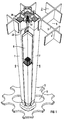
- the upper core lattice 2 shown in FIG. 1 is composed of upright webs 3 and 4 which penetrate at right angles and form square meshes 5.
- This upper core grid 2 is arranged horizontally in the core of a boiling water nuclear reactor.
- a mesh 5 of the upper core lattice 2 encloses four vertically arranged nuclear reactor fuel elements 6, each of which has an identical elongated fuel element box 7 with a square cross section, which surrounds fuel rods filled with nuclear fuel, a head plate 39 and a foot plate 13.
- Each of the nuclear reactor fuel elements 6 is arranged in a corner of the mesh 5, so that the fuel assembly boxes 7 of these nuclear reactor fuel elements 6 form a gap-shaped space with a cross-shaped cross section, in which an elongated control rod 8 with a cross-shaped cross section is also arranged to be displaceable in the vertical direction.
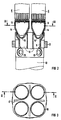
- the lower ends of the four nuclear reactor fuel elements 6 rest on a support body 9 shown in FIG. 2.
- This support body 9 is a cast body made of steel and is located in the upper end of a vertically arranged control rod guide tube 10 which, with its upper end, has a passage 11 in a core grid plate which can be seen in FIG 12 reaches through.
- This core grid plate 12 is arranged vertically below the upper core grid 2 in the boiling water core reactor and parallel to this upper core grid 2.
- the guide tubes 10 are not shown in FIG. 1 for the sake of a better overview.
- the nuclear reactor fuel elements 6 form a hollow truncated cone 14 at the bottom of their base plate 13 with a spherical cap 15 placed downward.
- Each of the nuclear reactor fuel elements 6 engages with the hollow truncated cone 14 in a circular opening 16 in the top of the supporting part 9, but loosely centered.
- the openings 16 can be seen in plan view in FIG. 3.
- the support part 9 has a passage opening 17 with a cross-shaped cross section for the control rod 8 between the four openings 16.
- the domes 15 also have wide passage gaps, and side openings 19 provided with shutters are provided in the jacket of the control rod guide tube 10.
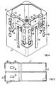
- the fuel element boxes 7 form flat and equally high gradations 20 on all four outer sides. With the gradations 20 from two adjacent sides of the fuel element boxes 7, each of the four nuclear reactor fuel elements 6 lies flat on a web 3 and 4 within the mesh of the nuclear lattice 2 Core 2 on. To the Gradations 20 of the other two sides of the fuel assembly 7 each have an angular part 21 which is screwed to a crossbar 22 of the fuel assembly 7 in question located on the outside at the corner of the fuel assembly 7.
- Such an angular part 21 can be seen more clearly in FIG. It has two legs 23 and 24 of equal length that are perpendicular to one another. On the same side of these legs 23 and 24 are walls 25 and 26 which are perpendicular to the apex web 27 of the legs 23 and 24 to each other and to the apex web 27.
- the walls 25 and 26 form in the apex web 27 an elongated L-profile 28 at right angles to the legs 23 and 24, while at the ends of the legs 23 and 24 they are each formed into a rigid, outwardly projecting system knobs 29 and 30.
- an elongated leaf spring 31 and 32 is arranged on both walls 25 and 26 in the direction of the L-profile 28 and is fastened at one end with a screw 33 and 34 to the angled part 2 so that it follows bulges away from the outside of the L-profile 28.
- the angle part is screwed to a transverse web 22 of the fuel assembly box 7 in such a way that the walls 25 and 26 with their inner surfaces are flat on the same gradations 20 on the outside on two adjacent sides of the fuel assembly box 7 in question in the mesh of the upper core lattice 2 according to FIG 1 concern.
- the leaf springs 31 and 32 on two opposite sides of two nuclear reactor fuel elements 7 in one mesh of the upper core lattice 2 according to FIG. 1 bear against one another under prestress.
- the walls of the fuel assembly boxes 7 of the nuclear reactor fuel assemblies 6 in FIG. 1 are particularly thin, the gradations 20 on the upper ends of these fuel assembly boxes cause the leaf springs 31 and 32 of the angle parts 21 in the center of the mesh of the upper core lattice 2 fix the four nuclear reactor fuel elements 6 in this mesh with an exactly vertically arranged longitudinal axis. Therefore, the space between the four nuclear reactor fuel elements 7 intended for the control rod 8 also has a precisely vertical longitudinal axis. The control rod 8 can therefore not jam in this space.
- a fuel assembly box 7 can e.g. with a square cross-section and a longitudinally running weld 37 on a step 20 in the outer sides at the upper end have an enlarged inner width.
- This gradation 20 can be impressively impressed into the starting plate for the fuel assembly 7 before this starting sheet is bent into the fuel assembly 7 and welded to two abutting end edges to form the weld seam 37.
- the fuel assembly box 7 has inwardly directed embossing points 40 at the gradations 20, at which the head plate 39 of the nuclear reactor fuel element 6 rests with its side faces.
Landscapes
- Physics & Mathematics (AREA)
- Engineering & Computer Science (AREA)
- Plasma & Fusion (AREA)
- General Engineering & Computer Science (AREA)
- High Energy & Nuclear Physics (AREA)
- Monitoring And Testing Of Nuclear Reactors (AREA)
- Fuel-Injection Apparatus (AREA)
- Springs (AREA)
Priority Applications (5)
| Application Number | Priority Date | Filing Date | Title |
|---|---|---|---|
| ES89112497T ES2049279T3 (es) | 1989-07-07 | 1989-07-07 | Elemento de combustion de reactor nuclear. |
| EP89112497A EP0406471B1 (de) | 1989-07-07 | 1989-07-07 | Kernreaktorbrennelement |
| DE89112497T DE58907044D1 (de) | 1989-07-07 | 1989-07-07 | Kernreaktorbrennelement. |
| FI903022A FI98869C (fi) | 1989-07-07 | 1990-06-15 | Ydinreaktoripolttoaine-elementti |
| JP2177210A JP2969132B2 (ja) | 1989-07-07 | 1990-07-04 | 原子炉燃料集合体 |
Applications Claiming Priority (1)
| Application Number | Priority Date | Filing Date | Title |
|---|---|---|---|
| EP89112497A EP0406471B1 (de) | 1989-07-07 | 1989-07-07 | Kernreaktorbrennelement |
Publications (2)
| Publication Number | Publication Date |
|---|---|
| EP0406471A1 EP0406471A1 (de) | 1991-01-09 |
| EP0406471B1 true EP0406471B1 (de) | 1994-02-23 |
Family
ID=8201596
Family Applications (1)
| Application Number | Title | Priority Date | Filing Date |
|---|---|---|---|
| EP89112497A Expired - Lifetime EP0406471B1 (de) | 1989-07-07 | 1989-07-07 | Kernreaktorbrennelement |
Country Status (5)
| Country | Link |
|---|---|
| EP (1) | EP0406471B1 (es) |
| JP (1) | JP2969132B2 (es) |
| DE (1) | DE58907044D1 (es) |
| ES (1) | ES2049279T3 (es) |
| FI (1) | FI98869C (es) |
Families Citing this family (1)
| Publication number | Priority date | Publication date | Assignee | Title |
|---|---|---|---|---|
| JP2011070061A (ja) | 2009-09-28 | 2011-04-07 | Ricoh Co Ltd | 電子写真用トナーの製造方法及び電子写真用トナー |
Family Cites Families (3)
| Publication number | Priority date | Publication date | Assignee | Title |
|---|---|---|---|---|
| DE2824265A1 (de) * | 1978-06-02 | 1979-12-06 | Kraftwerk Union Ag | Brennelement fuer siedewasserkernreaktoren |
| US4659543A (en) * | 1984-11-16 | 1987-04-21 | Westinghouse Electric Corp. | Cross brace for stiffening a water cross in a fuel assembly |
| GB8626238D0 (en) * | 1986-11-03 | 1986-12-03 | Nat Nuclear Corp Ltd | Nuclear reactor core restraint |
-
1989
- 1989-07-07 DE DE89112497T patent/DE58907044D1/de not_active Expired - Lifetime
- 1989-07-07 EP EP89112497A patent/EP0406471B1/de not_active Expired - Lifetime
- 1989-07-07 ES ES89112497T patent/ES2049279T3/es not_active Expired - Lifetime
-
1990
- 1990-06-15 FI FI903022A patent/FI98869C/fi not_active IP Right Cessation
- 1990-07-04 JP JP2177210A patent/JP2969132B2/ja not_active Expired - Lifetime
Also Published As
| Publication number | Publication date |
|---|---|
| FI98869C (fi) | 1997-08-25 |
| ES2049279T3 (es) | 1994-04-16 |
| FI903022A0 (fi) | 1990-06-15 |
| DE58907044D1 (de) | 1994-03-31 |
| JPH0344595A (ja) | 1991-02-26 |
| FI98869B (fi) | 1997-05-15 |
| JP2969132B2 (ja) | 1999-11-02 |
| EP0406471A1 (de) | 1991-01-09 |
Similar Documents
| Publication | Publication Date | Title |
|---|---|---|
| EP0517750B1 (de) | Siedewasserkernreaktor und kernreaktorbrennelement für diesen siedewasserkernreaktor | |
| EP0054827A1 (de) | Brennstabbündel für einen Siedewasserreaktor | |
| EP0517728B1 (de) | Kernreaktorbrennelement mit einem tragenden kühlmittelrohr | |
| EP0261544A1 (de) | Kernreaktorbrennelement | |
| DE3540466A1 (de) | Kernreaktorbrennelement | |
| DE3330850A1 (de) | Kernreaktorbrennelement | |
| EP0184064B2 (de) | Kernreaktorbrennelement | |
| DE3533317A1 (de) | Kernreaktorbrennelement | |
| EP0285920B1 (de) | Kernreaktorbrennelement | |
| EP0713600B1 (de) | Brennelement für einen siedewasserreaktor mit einstellbarem bypass | |
| DE2631925C3 (de) | Abstandshalter für wassergekühlte Kernreaktorbrennstäbe | |
| DE2106342C3 (de) | Brennstoffelement für einen Atomkernreaktor mit parallelen Brennstoffstäben | |
| EP0330013B1 (de) | Kernreaktorbrennelement | |
| DE2140170B2 (de) | Federndes Spannelement in Kernreaktoren | |
| EP0406471B1 (de) | Kernreaktorbrennelement | |
| DE2606074A1 (de) | Metallmast fuer regalfahrzeuge | |
| CH667550A5 (de) | Kernbrennstoffanordnung fuer einen siedewasserreaktor. | |
| EP0423382B1 (de) | Kernreaktorbrennelement | |
| EP0512132B1 (de) | Druckwasserreaktorbrennelement mit in das Fussteil integriertem Trümmerfänger | |
| EP0543253B1 (de) | Reaktorkern eines Kernreaktors und Kernreaktorbrennelement mit leichtgängigem Einsetzen | |
| EP0750318B1 (de) | Gitterförmiger Abstandhalter für ein Kernreaktorbrennelement und Kernreaktorbrennelement | |
| WO1993024933A1 (de) | Kernreaktorbrenstabbündel mit sechseckigem aus zusammengesetzten basiselementen bestehendem abstandhalter | |
| DE8330257U1 (de) | Doppelwandige stahlverbauplatte | |
| EP0057752A1 (de) | Lagergestell für stabförmige Brennelemente | |
| DE3216657A1 (de) | Brennelementbuendel fuer einen siedewasserreaktor |
Legal Events
| Date | Code | Title | Description |
|---|---|---|---|
| PUAI | Public reference made under article 153(3) epc to a published international application that has entered the european phase |
Free format text: ORIGINAL CODE: 0009012 |
|
| AK | Designated contracting states |
Kind code of ref document: A1 Designated state(s): CH DE ES LI SE |
|
| 17P | Request for examination filed |
Effective date: 19901220 |
|
| 17Q | First examination report despatched |
Effective date: 19930521 |
|
| GRAA | (expected) grant |
Free format text: ORIGINAL CODE: 0009210 |
|
| AK | Designated contracting states |
Kind code of ref document: B1 Designated state(s): CH DE ES LI SE |
|
| REF | Corresponds to: |
Ref document number: 58907044 Country of ref document: DE Date of ref document: 19940331 |
|
| REG | Reference to a national code |
Ref country code: ES Ref legal event code: FG2A Ref document number: 2049279 Country of ref document: ES Kind code of ref document: T3 |
|
| PLBE | No opposition filed within time limit |
Free format text: ORIGINAL CODE: 0009261 |
|
| STAA | Information on the status of an ep patent application or granted ep patent |
Free format text: STATUS: NO OPPOSITION FILED WITHIN TIME LIMIT |
|
| EAL | Se: european patent in force in sweden |
Ref document number: 89112497.6 |
|
| 26N | No opposition filed | ||
| PGFP | Annual fee paid to national office [announced via postgrant information from national office to epo] |
Ref country code: ES Payment date: 19980707 Year of fee payment: 10 |
|
| PGFP | Annual fee paid to national office [announced via postgrant information from national office to epo] |
Ref country code: CH Payment date: 19981102 Year of fee payment: 10 |
|
| PG25 | Lapsed in a contracting state [announced via postgrant information from national office to epo] |
Ref country code: ES Free format text: LAPSE BECAUSE OF NON-PAYMENT OF DUE FEES Effective date: 19990708 |
|
| PG25 | Lapsed in a contracting state [announced via postgrant information from national office to epo] |
Ref country code: LI Free format text: LAPSE BECAUSE OF NON-PAYMENT OF DUE FEES Effective date: 19990731 Ref country code: CH Free format text: LAPSE BECAUSE OF NON-PAYMENT OF DUE FEES Effective date: 19990731 |
|
| REG | Reference to a national code |
Ref country code: CH Ref legal event code: PL |
|
| REG | Reference to a national code |
Ref country code: ES Ref legal event code: FD2A Effective date: 20000810 |
|
| PGFP | Annual fee paid to national office [announced via postgrant information from national office to epo] |
Ref country code: DE Payment date: 20080924 Year of fee payment: 20 |
|
| PGFP | Annual fee paid to national office [announced via postgrant information from national office to epo] |
Ref country code: SE Payment date: 20080724 Year of fee payment: 20 |
|
| EUG | Se: european patent has lapsed |