EP0406471B1 - Nuclear reactor fuel element - Google Patents
Nuclear reactor fuel element Download PDFInfo
- Publication number
- EP0406471B1 EP0406471B1 EP89112497A EP89112497A EP0406471B1 EP 0406471 B1 EP0406471 B1 EP 0406471B1 EP 89112497 A EP89112497 A EP 89112497A EP 89112497 A EP89112497 A EP 89112497A EP 0406471 B1 EP0406471 B1 EP 0406471B1
- Authority
- EP
- European Patent Office
- Prior art keywords
- fuel element
- nuclear reactor
- casing
- fuel
- reactor fuel
- Prior art date
- Legal status (The legal status is an assumption and is not a legal conclusion. Google has not performed a legal analysis and makes no representation as to the accuracy of the status listed.)
- Expired - Lifetime
Links
- 239000003758 nuclear fuel Substances 0.000 title claims description 42
- 239000000446 fuel Substances 0.000 claims description 42
- XLYOFNOQVPJJNP-UHFFFAOYSA-N water Substances O XLYOFNOQVPJJNP-UHFFFAOYSA-N 0.000 description 9
- 238000009835 boiling Methods 0.000 description 8
- 238000004049 embossing Methods 0.000 description 3
- 230000000712 assembly Effects 0.000 description 2
- 238000000429 assembly Methods 0.000 description 2
- 229910000831 Steel Inorganic materials 0.000 description 1
- 229910001093 Zr alloy Inorganic materials 0.000 description 1
- 239000011358 absorbing material Substances 0.000 description 1
- 239000010959 steel Substances 0.000 description 1
Images
Classifications
-
- G—PHYSICS
- G21—NUCLEAR PHYSICS; NUCLEAR ENGINEERING
- G21C—NUCLEAR REACTORS
- G21C3/00—Reactor fuel elements and their assemblies; Selection of substances for use as reactor fuel elements
- G21C3/30—Assemblies of a number of fuel elements in the form of a rigid unit
- G21C3/32—Bundles of parallel pin-, rod-, or tube-shaped fuel elements
- G21C3/324—Coats or envelopes for the bundles
-
- G—PHYSICS
- G21—NUCLEAR PHYSICS; NUCLEAR ENGINEERING
- G21C—NUCLEAR REACTORS
- G21C3/00—Reactor fuel elements and their assemblies; Selection of substances for use as reactor fuel elements
- G21C3/02—Fuel elements
- G21C3/04—Constructional details
- G21C3/06—Casings; Jackets
- G21C3/12—Means forming part of the element for locating it within the reactor core
-
- Y—GENERAL TAGGING OF NEW TECHNOLOGICAL DEVELOPMENTS; GENERAL TAGGING OF CROSS-SECTIONAL TECHNOLOGIES SPANNING OVER SEVERAL SECTIONS OF THE IPC; TECHNICAL SUBJECTS COVERED BY FORMER USPC CROSS-REFERENCE ART COLLECTIONS [XRACs] AND DIGESTS
- Y02—TECHNOLOGIES OR APPLICATIONS FOR MITIGATION OR ADAPTATION AGAINST CLIMATE CHANGE
- Y02E—REDUCTION OF GREENHOUSE GAS [GHG] EMISSIONS, RELATED TO ENERGY GENERATION, TRANSMISSION OR DISTRIBUTION
- Y02E30/00—Energy generation of nuclear origin
- Y02E30/30—Nuclear fission reactors
Definitions
- the invention relates to a nuclear reactor fuel element according to the preamble of claim 1.
- Such a nuclear reactor fuel element is known from German Offenlegungsschrift 28 24 265. Its fuel assembly box has a square cross section. Together with three other nuclear reactor fuel elements, the fuel element boxes of which have the same square cross section, it forms a group of four vertically arranged nuclear reactor fuel elements. The upper ends of the fuel assembly boxes are combined in a square mesh of a so-called upper core grid in the boiling water core reactor. Each nuclear reactor fuel element is located in a corner of this square mesh, and its fuel assembly box lies flat on two sides of this square mesh on this upper core grid.
- the angular parts at the corner of the fuel assembly box of each of these four nuclear reactor fuel assemblies are located in the center of the mesh of the upper core lattice.
- two opposite leaf springs of the angular parts of two nuclear reactor fuel elements touch each other and thus ensure that a gap-shaped space with a cross-shaped cross section is formed between the fuel element boxes of the four nuclear reactor fuel elements.
- an elongated control rod with a cross-shaped cross section is arranged to be displaceable in the vertical direction.
- the lower ends of the four nuclear reactor fuel elements are loosely but centrally supported in the boiling water nuclear reactor so that each of these four nuclear reactor fuel elements is about its lower end is pivotable in any direction transverse to its longitudinal axis.
- the invention has for its object to provide a nuclear reactor fuel element which brings about an improved neutron economy in a boiling water nuclear reactor.
- a nuclear reactor fuel element of the type mentioned at the outset has the features of the characterizing part of patent claim 1.
- the fuel element box which generally consists of zirconium alloy, introduces relatively little neutron-absorbing material into the boiling water reactor.
- the dimensions of the peaks at the top of the fuel assembly box can be chosen so that four nuclear reactor fuel elements with the same fuel assembly box are arranged in the mesh of an upper core grid already specified in a nuclear reactor, do not tilt in this mesh and thereby impair the functionality of the control rod arranged between them .
- Claims 2 to 5 are directed to advantageous designs of the nuclear reactor fuel element, by means of which the fuel assembly box can be manufactured cheaply.
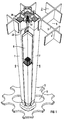
- the upper core lattice 2 shown in FIG. 1 is composed of upright webs 3 and 4 which penetrate at right angles and form square meshes 5.
- This upper core grid 2 is arranged horizontally in the core of a boiling water nuclear reactor.
- a mesh 5 of the upper core lattice 2 encloses four vertically arranged nuclear reactor fuel elements 6, each of which has an identical elongated fuel element box 7 with a square cross section, which surrounds fuel rods filled with nuclear fuel, a head plate 39 and a foot plate 13.
- Each of the nuclear reactor fuel elements 6 is arranged in a corner of the mesh 5, so that the fuel assembly boxes 7 of these nuclear reactor fuel elements 6 form a gap-shaped space with a cross-shaped cross section, in which an elongated control rod 8 with a cross-shaped cross section is also arranged to be displaceable in the vertical direction.
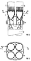
- the lower ends of the four nuclear reactor fuel elements 6 rest on a support body 9 shown in FIG. 2.
- This support body 9 is a cast body made of steel and is located in the upper end of a vertically arranged control rod guide tube 10 which, with its upper end, has a passage 11 in a core grid plate which can be seen in FIG 12 reaches through.
- This core grid plate 12 is arranged vertically below the upper core grid 2 in the boiling water core reactor and parallel to this upper core grid 2.
- the guide tubes 10 are not shown in FIG. 1 for the sake of a better overview.
- the nuclear reactor fuel elements 6 form a hollow truncated cone 14 at the bottom of their base plate 13 with a spherical cap 15 placed downward.
- Each of the nuclear reactor fuel elements 6 engages with the hollow truncated cone 14 in a circular opening 16 in the top of the supporting part 9, but loosely centered.
- the openings 16 can be seen in plan view in FIG. 3.
- the support part 9 has a passage opening 17 with a cross-shaped cross section for the control rod 8 between the four openings 16.
- the domes 15 also have wide passage gaps, and side openings 19 provided with shutters are provided in the jacket of the control rod guide tube 10.
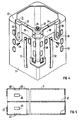
- the fuel element boxes 7 form flat and equally high gradations 20 on all four outer sides. With the gradations 20 from two adjacent sides of the fuel element boxes 7, each of the four nuclear reactor fuel elements 6 lies flat on a web 3 and 4 within the mesh of the nuclear lattice 2 Core 2 on. To the Gradations 20 of the other two sides of the fuel assembly 7 each have an angular part 21 which is screwed to a crossbar 22 of the fuel assembly 7 in question located on the outside at the corner of the fuel assembly 7.
- Such an angular part 21 can be seen more clearly in FIG. It has two legs 23 and 24 of equal length that are perpendicular to one another. On the same side of these legs 23 and 24 are walls 25 and 26 which are perpendicular to the apex web 27 of the legs 23 and 24 to each other and to the apex web 27.
- the walls 25 and 26 form in the apex web 27 an elongated L-profile 28 at right angles to the legs 23 and 24, while at the ends of the legs 23 and 24 they are each formed into a rigid, outwardly projecting system knobs 29 and 30.
- an elongated leaf spring 31 and 32 is arranged on both walls 25 and 26 in the direction of the L-profile 28 and is fastened at one end with a screw 33 and 34 to the angled part 2 so that it follows bulges away from the outside of the L-profile 28.
- the angle part is screwed to a transverse web 22 of the fuel assembly box 7 in such a way that the walls 25 and 26 with their inner surfaces are flat on the same gradations 20 on the outside on two adjacent sides of the fuel assembly box 7 in question in the mesh of the upper core lattice 2 according to FIG 1 concern.
- the leaf springs 31 and 32 on two opposite sides of two nuclear reactor fuel elements 7 in one mesh of the upper core lattice 2 according to FIG. 1 bear against one another under prestress.
- the walls of the fuel assembly boxes 7 of the nuclear reactor fuel assemblies 6 in FIG. 1 are particularly thin, the gradations 20 on the upper ends of these fuel assembly boxes cause the leaf springs 31 and 32 of the angle parts 21 in the center of the mesh of the upper core lattice 2 fix the four nuclear reactor fuel elements 6 in this mesh with an exactly vertically arranged longitudinal axis. Therefore, the space between the four nuclear reactor fuel elements 7 intended for the control rod 8 also has a precisely vertical longitudinal axis. The control rod 8 can therefore not jam in this space.
- a fuel assembly box 7 can e.g. with a square cross-section and a longitudinally running weld 37 on a step 20 in the outer sides at the upper end have an enlarged inner width.
- This gradation 20 can be impressively impressed into the starting plate for the fuel assembly 7 before this starting sheet is bent into the fuel assembly 7 and welded to two abutting end edges to form the weld seam 37.
- the fuel assembly box 7 has inwardly directed embossing points 40 at the gradations 20, at which the head plate 39 of the nuclear reactor fuel element 6 rests with its side faces.
Landscapes
- Physics & Mathematics (AREA)
- Engineering & Computer Science (AREA)
- Plasma & Fusion (AREA)
- General Engineering & Computer Science (AREA)
- High Energy & Nuclear Physics (AREA)
- Monitoring And Testing Of Nuclear Reactors (AREA)
- Fuel-Injection Apparatus (AREA)
- Springs (AREA)
Description
Die Erfindung betrifft ein Kernreaktorbrennelement nach dem Oberbegriff des Patentanspruches 1.The invention relates to a nuclear reactor fuel element according to the preamble of claim 1.
Ein derartiges Kernreaktorbrennelement ist aus der deutschen Offenlegungsschrift 28 24 265 bekannt. Sein Brennelementkasten hat quadratischen Querschnitt. Es bildet zusammen mit drei weiteren Kernreraktorbrennelementen, deren Brennelementkästen den gleichen quadratischen Querschnitt haben, eine Gruppe von vier vertikal angeordneten Kernreaktorbrennelementen. Die Oberenden der Brennelementkästen sind in einer quadratischen Masche eines sogenannten oberen Kerngitters im Siedewasserkernreaktor zusammengefaßt. Jedes Kernreaktorbrennelement befindet sich in einer Ecke dieser quadratischen Masche, und sein Brennelementkasten liegt flächig an zwei Seiten dieser quadratischen Masche an diesem oberen Kerngitter an.Such a nuclear reactor fuel element is known from German Offenlegungsschrift 28 24 265. Its fuel assembly box has a square cross section. Together with three other nuclear reactor fuel elements, the fuel element boxes of which have the same square cross section, it forms a group of four vertically arranged nuclear reactor fuel elements. The upper ends of the fuel assembly boxes are combined in a square mesh of a so-called upper core grid in the boiling water core reactor. Each nuclear reactor fuel element is located in a corner of this square mesh, and its fuel assembly box lies flat on two sides of this square mesh on this upper core grid.
Die Winkelteile an der Ecke des Brennelementkastens eines jeden dieser vier Kernreaktorbrennelemente befinden sich im Zentrum der Masche des oberen Kerngitters. Dort berühren sich jeweils zwei gegenüberliegende Blattfedern der Winkelteile von zwei Kernreaktorbrennelementen und gewährleisten so, daß sich zwischen den Brennelementkästen der vier Kernreaktorbrennelemente ein spaltförmiger Zwischenraum mit kreuzförmigem Querschnitt bildet. In diesem Zwischenraum ist ein langgestreckter Steuerstab mit ebenfalls kreuzförmigem Querschnitt in vertikaler Richtung verschiebbar angeordnet.The angular parts at the corner of the fuel assembly box of each of these four nuclear reactor fuel assemblies are located in the center of the mesh of the upper core lattice. There, two opposite leaf springs of the angular parts of two nuclear reactor fuel elements touch each other and thus ensure that a gap-shaped space with a cross-shaped cross section is formed between the fuel element boxes of the four nuclear reactor fuel elements. In this intermediate space, an elongated control rod with a cross-shaped cross section is arranged to be displaceable in the vertical direction.
Die unteren Enden der vier Kernreaktorbrennelemente sind in dem Siedewasserkernreaktor lose, aber zentriert abgestützt, so daß jedes dieser vier Kernreaktorbrennelemente um sein Unterende in jeder Richtung quer zu seiner Längsachse schwenkbar ist.The lower ends of the four nuclear reactor fuel elements are loosely but centrally supported in the boiling water nuclear reactor so that each of these four nuclear reactor fuel elements is about its lower end is pivotable in any direction transverse to its longitudinal axis.
Der Erfindung liegt die Aufgabe zugrunde, ein Kernreaktorbrennelement zu schaffen, das eine verbesserte Neutronenökonomie in einem Siedewasserkernreaktor bewirkt.The invention has for its object to provide a nuclear reactor fuel element which brings about an improved neutron economy in a boiling water nuclear reactor.
Zur Lösung dieser Aufgabe hat ein Kernreaktorbrennelement der eingangs erwähnten Art erfindungsgemäß die Merkmale des kennzeichnenden Teiles des Patentanspruches 1.To achieve this object, a nuclear reactor fuel element of the type mentioned at the outset has the features of the characterizing part of patent claim 1.
Dadurch ist gewährleistet, daß der in der Regel aus Zirkoniumlegierung bestehende Brennelementkasten verhältnismäßig wenig neutronenabsorbierenden Werkstoff in den Siedewasserkernreaktor einbringt. Zugleich können aber die Abmessungen der Überhöhungen am Oberende des Brennelementkastens so gewählt werden, daß vier Kernreaktorbrennelemente mit gleichartigem Brennelementkasten in der Masche eines in einem Kernreaktor bereits vorgegebenen oberen Kerngitters angeordnet sind, in dieser Masche nicht kippen und dadurch die Funktionsfähigkeit des zwischen ihnen angeordneten Steuerstabes beeinträchtigen.This ensures that the fuel element box, which generally consists of zirconium alloy, introduces relatively little neutron-absorbing material into the boiling water reactor. At the same time, however, the dimensions of the peaks at the top of the fuel assembly box can be chosen so that four nuclear reactor fuel elements with the same fuel assembly box are arranged in the mesh of an upper core grid already specified in a nuclear reactor, do not tilt in this mesh and thereby impair the functionality of the control rod arranged between them .
Die Patentansprüche 2 bis 5 sind auf vorteilhafte Ausbildungen des Kernreaktorbrennelementes gerichtet, durch die der Brennelementkasten günstig gefertigt werden kann.Claims 2 to 5 are directed to advantageous designs of the nuclear reactor fuel element, by means of which the fuel assembly box can be manufactured cheaply.
Die Erfindung und ihre Vorteile seien anhand der Zeichnung an Ausführungsbeispielen näher erläutert:
- FIG 1 zeigt in perspektivischer Ansicht eine Masche eines oberen Kerngitters in einem Siedewasserkernreaktor.
- FIG 2 zeigt im Längsschnitt entsprechend der strichpunktierten Linie II-II in FIG 3 die Unterenden von zwei in der Masche nach FIG 1 angeordneten Kernreaktorbrennelementen.
- FIG 3 zeigt in Draufsicht einen in FIG 2 erkennbaren Gußkörper.
- FIG 4 zeigt in perspektivischer Ansicht eine Ecke am Oberende eines Brennelementkastens für ein in die Masche des oberen Kerngitters nach FIG 1 einsetzbares Kernreaktorbrennelement.
- FIG 5 zeigt in Seitenansicht einen Brennelementkasten für ein in die Masche des oberen Kerngitters nach FIG 1 einsetzbares Kernreaktorbrennelement.
- 1 shows a perspective view of a mesh of an upper core lattice in a boiling water nuclear reactor.
- 2 shows in longitudinal section corresponding to the dash-dotted line II-II in FIG. 3 the lower ends of two nuclear reactor fuel elements arranged in the mesh according to FIG.
- 3 shows a cast body recognizable in FIG.
- 4 shows a perspective view of a corner at the upper end of a fuel assembly box for a nuclear reactor fuel assembly which can be inserted into the mesh of the upper core lattice according to FIG.
- 5 shows a side view of a fuel assembly box for a nuclear reactor fuel assembly that can be inserted into the mesh of the upper core grid according to FIG. 1.
Das in FIG 1 dargestellte obere Kerngitter 2 setzt sich aus hochkant angeordneten, sich rechtwinklig durchsetzenden Stegen 3 und 4 zusammen, die quadratische Maschen 5 bilden. Dieses obere Kerngitter 2 ist horizontal im Kern eines Siedewasserkernreaktors angeordnet.The upper core lattice 2 shown in FIG. 1 is composed of
Eine Masche 5 des oberen Kerngitters 2 umschließt jeweils vier vertikal angeordnete Kernreaktorbrennelemente 6, von denen jedes einen gleich ausgebildeten langgestreckten Brennelementkasten 7 mit quadratischem Querschnitt aufweist, der mit Kernbrennstoff gefüllte Brennstäbe, eine Kopfplatte 39 und eine Fußplatte 13 umhüllt. Jedes der Kernreaktorbrennelemente 6 ist in einer Ecke der Masche 5 angeordnet, so daß die Brennelementkästen 7 dieser Kernreaktorbrennelemente 6 einen spaltförmigen Zwischenraum mit kreuzförmigem Querschnitt bilden, in dem ein langgestreckter Steuerstab 8 mit ebenfalls kreuzförmigem Querschnitt in vertikaler Richtung verschiebbar angeordnet ist.A mesh 5 of the upper core lattice 2 encloses four vertically arranged nuclear
Die unteren Enden der vier Kernreaktorbrennelemente 6 ruhen auf einem in FIG 2 dargestellten Stützkörper 9. Dieser Stützkörper 9 ist ein Gußkörper aus Stahl und befindet sich im Oberende eines vertikal angeordneten Steuerstabführungsrohres 10, das mit seinem Oberende eine Durchführung 11 in einer in FIG 1 erkennbaren Kerngitterplatte 12 durchgreift. Diese Kerngitterplatte 12 ist im Siedewasserkernreaktor vertikal unterhalb des oberen Kerngitters 2 angeordnet und parallel zu diesem oberen Kerngitter 2. Die Führungsrohre 10 sind der besseren Übersicht halber in FIG 1 nicht dargestellt.The lower ends of the four nuclear
Wie FIG 2 ferner zeigt, bilden die Kernreaktorbrennelemente 6 unten an ihrer Fußplatte 13 einen hohlen Kegelstumpf 14 mit nach unten aufgesetzter Kalotte 15. Jedes der Kernreaktorbrennelemente 6 greift mit dem hohlen Kegelstumpf 14 in eine kreisrunde Öffnung 16 in der Oberseite des Stützteiles 9 lose, aber zentriert. Die Öffnungen 16 sind in Draufsicht in FIG 3 zu erkennen. Das Stützteil 9 hat zwischen den vier Öffnungen 16 eine Durchtrittsöffnung 17 mit kreuzförmigem Querschnitt für den Steuerstab 8. Ferner befinden sich im Stützteil 9 an den Öffnungen 16 Kanäle 18, die durchgehend sind vom Unterende des Stützteiles 9 bis zu dessen Oberende. Auch die Kalotten 15 weisen breite Durchtrittsspalte auf, und im Mantel des Steuerstabführungsrohres 10 sind mit Blenden versehene Seitenöffnungen 19 vorgesehen. Im Siedewasserkernreaktor kann also Wasser aus dem Steuerstabführungsrohr 10 und durch die Seitenöffnungen 19 hindurch in die Kanäle 18 des Stützteiles 9 aufsteigen und durch die Durchtrittsspalte in den Kalotten 15 und die hohlen Kegelstümpfe 14 sowie durch Durchführungen in den Fußplatten 13 der Kernreaktorbrennelemente 6 hindurch in die Kernreaktorbrennelemente 6 gelangen und diese von unten nach oben durchfließen. Zugleich sind diese Kernreaktorbrennelemente 6 in den Öffnungen 16 des Stützteiles 9 quer zur Längsachse dieser Kernreaktorbrennelemente 6 schwenkbar lose abgestützt und zentriert.As FIG 2 also shows, the nuclear
Am Oberende der Kernreaktorbrennelemente 6 bilden die Brennelementkästen 7 auf allen vier Außenseiten flache und gleichhohe Abstufungen 20. Mit den Abstufungen 20 von zwei benachbarten Seiten der Brennelementkästen 7 liegt jedes der vier Kernreaktorbrennelemente 6 innerhalb der Masche des Kerngitters 2 flächig an einem Steg 3 und 4 des Kerngitters 2 an. An den Abstufungen 20 der beiden anderen Seiten der Brennelementkästen 7 liegt jeweils ein Winkelteil 21 an, das an einem Quersteg 22 des betreffenden Brennelementkastens 7 außen an der Ecke des Brennelementkastens 7 befindlich festgeschraubt ist.At the upper end of the nuclear
Ein solches Winkelteil 21 ist in FIG 4 deutlicher erkennbar. Es weist zwei zueinander rechtwinklige, gleichlange Schenkel 23 und 24 auf. An der gleichen Seite dieser Schenkel 23 und 24 befinden sich Wandungen 25 und 26, die in einem Scheitelsteg 27 der Schenkel 23 und 24 zueinander und zum Scheitelsteg 27 rechtwinklig sind. Die Wandungen 25 und 26 bilden im Scheitelsteg 27 ein zu den Schenkeln 23 und 24 rechtwinkliges langgestrecktes L-Profil 28, während sie an den Enden der Schenkel 23 und 24 jeweils zu einem starren, sich nach außen erhebenden Anlagennoppen 29 und 30 ausgeformt sind.Such an
Außen am L-förmigen Profil 28 ist auf beiden Wandungen 25 und 26 je eine langgestreckte Blattfeder 31 und 32 in Richtung des L-Profils 28 angeordnet und jeweils an einem Ende mit einer Schraube 33 und 34 am Winkelteil 2 so befestigt, daß sie sich nach außen von der Außenseite des L-Profils 28 wegwölbt. Mit einem Schraubbolzen 35 ist das Winkelteil derart an einem Quersteg 22 des Brennelementkastens 7 festgeschraubt, daß die Wandungen 25 und 26 mit ihren Innenseiten flächig an den gleichhohen Abstufungen 20 außen an zwei benachbarten Seiten des betreffenden Brennelementkastens 7 in der Masche des oberen Kerngitters 2 nach FIG 1 anliegen.On the outside of the L-
Die Blattfedern 31 bzw. 32 an zwei sich gegenüberliegenden Seiten von jeweils zwei Kernreaktorbrennelementen 7 in einer Masche des oberen Kerngitters 2 nach FIG 1 liegen unter Vorspannung aneinander an. Obwohl die Wandungen der Brennelementkästen 7 der Kernreaktorbrennelemente 6 in FIG 1 besonders dünn ausgeführt sind, bewirken die Abstufungen 20 an den Oberenden dieser Brennelementkästen, daß die Blattfedern 31 bzw. 32 der Winkelteile 21 im Zentrum der Masche des oberen Kerngitters 2 die vier Kernreaktorbrennelemente 6 in dieser Masche mit genau vertikal angeordneter Längsachse fixieren. Deshalb hat auch der für den Steuerstab 8 bestimmte Zwischenraum zwischen den vier Kernreaktorbrennelementen 7 eine genau vertikale Längsachse. Der Steuerstab 8 kann daher in diesem Zwischenraum nicht verklemmen.The leaf springs 31 and 32 on two opposite sides of two nuclear
Wie FIG 4 zeigt, können anstelle der Abstufungen 20 am Oberende des Brennelementkastens 7 an den Außenseiten auch nach außen gerichtete, gleichhohe lokale Prägestellen 36 vorgesehen sein, an denen die Wandungen 25 und 26 des Winkelteils 21 und in der Masche des oberen Kerngitters 2 nach FIG 1 die Stege 3 und 4 dieses oberen Kerngitters 2 flächig anliegen. Die Prägestellen 36 sind besonders günstig am Brennelementkasten 7 herstellbar.As shown in FIG. 4, instead of the
Nach FIG 5 kann ein Brennelementkasten 7 z.B. mit quadratischem Querschnitt und einer in Längsrichtung verlaufenden Schweißnaht 37 an einer Abstufung 20 in den Außenseiten am Oberende eine vergrößerte Innenweite haben. Diese Abstufung 20 kann günstig in das Ausgangsblech für den Brennelementkasten 7 eingeprägt werden, bevor dieses Ausgangsblech zum Brennelementkasten 7 gebogen und an zwei aneinanderstoßenden Endkanten unter Ausbildung der Schweißnaht 37 verschweißt wird. Günstigerweise hat der Brennelementkasten 7 an den Abstufungen 20 nach innen gerichtete Prägestellen 40, an denen die Kopfplatte 39 des Kernreaktorbrennelementes 6 mit ihren Seitenflächen anliegt.According to FIG. 5, a
Claims (5)
- Nuclear reactor fuel element having fuel rods which contain nuclear fuel and are guided in bushings in a top plate and a base plate and at least some of which are secured in these bushings, having an elongated fuel element casing which has a rectangular cross section, in particular a square cross section, which surrounds the top plate and the base plate having the fuel rods and which is secured to the top plate at an upper end, as well as an angle part adapted to the fuel element casing, which angle part is attached to the upper end of the fuel element casing at one corner, bears against two adjacent outer sides of the fuel element casing and is provided on these two outer sides of the fuel element casing with a respective leaf spring extending in the longitudinal direction of the casing, characterised in that the outer sides of the fuel element casing (7) have superelevations of equal height at the upper end of the said casing and in that the angle part (21) bears against superelevations of this type formed in the two outer sides of the fuel element casing (7).
- Nuclear reactor fuel element according to claim 1, characterised in that the superelevations are formed by a graduation (20) in the outer sides of the fuel element casing (7).
- Nuclear reactor fuel element according to claim 1, characterised in that the superelevations are formed by outwardly directed embossed places (36).
- Nuclear reactor fuel element according to claim 2, characterised in that the fuel element casing (7) has an enlarged internal width at the graduations (20).
- Nuclear reactor fuel element according to claim 4, characterised in that the fuel element casing (7) has embossed places (40) facing inwards on the graduations (20), with the top plate (39) bearing against these embossed places.
Priority Applications (5)
| Application Number | Priority Date | Filing Date | Title |
|---|---|---|---|
| EP89112497A EP0406471B1 (en) | 1989-07-07 | 1989-07-07 | Nuclear reactor fuel element |
| DE89112497T DE58907044D1 (en) | 1989-07-07 | 1989-07-07 | Nuclear reactor fuel element. |
| ES89112497T ES2049279T3 (en) | 1989-07-07 | 1989-07-07 | NUCLEAR REACTOR COMBUSTION ELEMENT. |
| FI903022A FI98869C (en) | 1989-07-07 | 1990-06-15 | Nuclear reactor fuel element |
| JP2177210A JP2969132B2 (en) | 1989-07-07 | 1990-07-04 | Reactor fuel assembly |
Applications Claiming Priority (1)
| Application Number | Priority Date | Filing Date | Title |
|---|---|---|---|
| EP89112497A EP0406471B1 (en) | 1989-07-07 | 1989-07-07 | Nuclear reactor fuel element |
Publications (2)
| Publication Number | Publication Date |
|---|---|
| EP0406471A1 EP0406471A1 (en) | 1991-01-09 |
| EP0406471B1 true EP0406471B1 (en) | 1994-02-23 |
Family
ID=8201596
Family Applications (1)
| Application Number | Title | Priority Date | Filing Date |
|---|---|---|---|
| EP89112497A Expired - Lifetime EP0406471B1 (en) | 1989-07-07 | 1989-07-07 | Nuclear reactor fuel element |
Country Status (5)
| Country | Link |
|---|---|
| EP (1) | EP0406471B1 (en) |
| JP (1) | JP2969132B2 (en) |
| DE (1) | DE58907044D1 (en) |
| ES (1) | ES2049279T3 (en) |
| FI (1) | FI98869C (en) |
Cited By (1)
| Publication number | Priority date | Publication date | Assignee | Title |
|---|---|---|---|---|
| WO2025003596A1 (en) * | 2023-06-30 | 2025-01-02 | Calogena | Nuclear reactor core arrangement and method for handling this arrangement |
Families Citing this family (1)
| Publication number | Priority date | Publication date | Assignee | Title |
|---|---|---|---|---|
| JP2011070061A (en) | 2009-09-28 | 2011-04-07 | Ricoh Co Ltd | Method for producing electrophotographic toner and electrophotographic toner |
Family Cites Families (3)
| Publication number | Priority date | Publication date | Assignee | Title |
|---|---|---|---|---|
| DE2824265A1 (en) * | 1978-06-02 | 1979-12-06 | Kraftwerk Union Ag | FUEL ELEMENT FOR BOILING WATER NUCLEAR REACTORS |
| US4659543A (en) * | 1984-11-16 | 1987-04-21 | Westinghouse Electric Corp. | Cross brace for stiffening a water cross in a fuel assembly |
| GB8626238D0 (en) * | 1986-11-03 | 1986-12-03 | Nat Nuclear Corp Ltd | Nuclear reactor core restraint |
-
1989
- 1989-07-07 EP EP89112497A patent/EP0406471B1/en not_active Expired - Lifetime
- 1989-07-07 ES ES89112497T patent/ES2049279T3/en not_active Expired - Lifetime
- 1989-07-07 DE DE89112497T patent/DE58907044D1/en not_active Expired - Lifetime
-
1990
- 1990-06-15 FI FI903022A patent/FI98869C/en not_active IP Right Cessation
- 1990-07-04 JP JP2177210A patent/JP2969132B2/en not_active Expired - Lifetime
Cited By (2)
| Publication number | Priority date | Publication date | Assignee | Title |
|---|---|---|---|---|
| WO2025003596A1 (en) * | 2023-06-30 | 2025-01-02 | Calogena | Nuclear reactor core arrangement and method for handling this arrangement |
| FR3150633A1 (en) * | 2023-06-30 | 2025-01-03 | Calogena | NUCLEAR REACTOR CORE ARRANGEMENT AND METHOD FOR HANDLING SAID ARRANGEMENT |
Also Published As
| Publication number | Publication date |
|---|---|
| FI903022A0 (en) | 1990-06-15 |
| JP2969132B2 (en) | 1999-11-02 |
| ES2049279T3 (en) | 1994-04-16 |
| FI98869B (en) | 1997-05-15 |
| EP0406471A1 (en) | 1991-01-09 |
| FI98869C (en) | 1997-08-25 |
| JPH0344595A (en) | 1991-02-26 |
| DE58907044D1 (en) | 1994-03-31 |
Similar Documents
| Publication | Publication Date | Title |
|---|---|---|
| EP0054827A1 (en) | Fuel assembly for a boiling water nuclear reator | |
| DE4006264A1 (en) | BOILER WATER CORE REACTOR AND CORE REACTOR FUEL ELEMENT FOR THIS BOILER WATER CORE REACTOR | |
| DE2742946C2 (en) | Spring element for holding down nuclear reactor fuel elements | |
| EP0517728B1 (en) | Nuclear reactor fuel element with a supporting coolant pipe | |
| EP0224728B1 (en) | Boiling water nuclear reactor fuel assembly | |
| EP0261544A1 (en) | Nuclear reactor fuel element | |
| EP0141208B1 (en) | Fuel assembly for a nuclear reactor | |
| DE3330850A1 (en) | CORE REACTOR FUEL ELEMENT | |
| EP0184064B2 (en) | Nuclear reactor fuel element | |
| DE69715620T2 (en) | Nuclear fuel assemblies | |
| DE3533317A1 (en) | Nuclear reactor fuel element | |
| DE2106342C3 (en) | Fuel element for an atomic nuclear reactor with parallel fuel rods | |
| EP0713600B1 (en) | Fuel element for a boiling water reactor with adjustable by-pass | |
| DE2631925C3 (en) | Spacers for water-cooled nuclear reactor fuel rods | |
| DE2140170B2 (en) | Resilient tensioning element in nuclear reactors | |
| EP0406471B1 (en) | Nuclear reactor fuel element | |
| DE2606074A1 (en) | METAL MAST FOR SHELVING VEHICLES | |
| WO1993024933A1 (en) | Bundle of nuclear-reactor fuel rods with hexagonal spacers made up of an assembly of basic components | |
| CH667550A5 (en) | NUCLEAR FUEL ARRANGEMENT FOR A BOILING WATER REACTOR. | |
| EP0423382B1 (en) | Nuclear-fuel assembly | |
| EP0057752B1 (en) | Storage rack for fuel rods | |
| EP0512132B1 (en) | Nuclear pressure water fuel assembly comprising a bottom nozzle with integrated debris catcher | |
| EP0543253B1 (en) | Nuclear reactor core and fuel element with easier positioning | |
| EP0750318B1 (en) | Spacer grid for nuclear reactor fuel assembly and fuel assembly with such a spacer grid | |
| DE4123726A1 (en) | CORE REACTOR FUEL ELEMENT |
Legal Events
| Date | Code | Title | Description |
|---|---|---|---|
| PUAI | Public reference made under article 153(3) epc to a published international application that has entered the european phase |
Free format text: ORIGINAL CODE: 0009012 |
|
| AK | Designated contracting states |
Kind code of ref document: A1 Designated state(s): CH DE ES LI SE |
|
| 17P | Request for examination filed |
Effective date: 19901220 |
|
| 17Q | First examination report despatched |
Effective date: 19930521 |
|
| GRAA | (expected) grant |
Free format text: ORIGINAL CODE: 0009210 |
|
| AK | Designated contracting states |
Kind code of ref document: B1 Designated state(s): CH DE ES LI SE |
|
| REF | Corresponds to: |
Ref document number: 58907044 Country of ref document: DE Date of ref document: 19940331 |
|
| REG | Reference to a national code |
Ref country code: ES Ref legal event code: FG2A Ref document number: 2049279 Country of ref document: ES Kind code of ref document: T3 |
|
| PLBE | No opposition filed within time limit |
Free format text: ORIGINAL CODE: 0009261 |
|
| STAA | Information on the status of an ep patent application or granted ep patent |
Free format text: STATUS: NO OPPOSITION FILED WITHIN TIME LIMIT |
|
| EAL | Se: european patent in force in sweden |
Ref document number: 89112497.6 |
|
| 26N | No opposition filed | ||
| PGFP | Annual fee paid to national office [announced via postgrant information from national office to epo] |
Ref country code: ES Payment date: 19980707 Year of fee payment: 10 |
|
| PGFP | Annual fee paid to national office [announced via postgrant information from national office to epo] |
Ref country code: CH Payment date: 19981102 Year of fee payment: 10 |
|
| PG25 | Lapsed in a contracting state [announced via postgrant information from national office to epo] |
Ref country code: ES Free format text: LAPSE BECAUSE OF NON-PAYMENT OF DUE FEES Effective date: 19990708 |
|
| PG25 | Lapsed in a contracting state [announced via postgrant information from national office to epo] |
Ref country code: LI Free format text: LAPSE BECAUSE OF NON-PAYMENT OF DUE FEES Effective date: 19990731 Ref country code: CH Free format text: LAPSE BECAUSE OF NON-PAYMENT OF DUE FEES Effective date: 19990731 |
|
| REG | Reference to a national code |
Ref country code: CH Ref legal event code: PL |
|
| REG | Reference to a national code |
Ref country code: ES Ref legal event code: FD2A Effective date: 20000810 |
|
| PGFP | Annual fee paid to national office [announced via postgrant information from national office to epo] |
Ref country code: DE Payment date: 20080924 Year of fee payment: 20 |
|
| PGFP | Annual fee paid to national office [announced via postgrant information from national office to epo] |
Ref country code: SE Payment date: 20080724 Year of fee payment: 20 |
|
| EUG | Se: european patent has lapsed |