EP0405740A2 - Oberflächeninterferenz-Detektor - Google Patents
Oberflächeninterferenz-Detektor Download PDFInfo
- Publication number
- EP0405740A2 EP0405740A2 EP90305394A EP90305394A EP0405740A2 EP 0405740 A2 EP0405740 A2 EP 0405740A2 EP 90305394 A EP90305394 A EP 90305394A EP 90305394 A EP90305394 A EP 90305394A EP 0405740 A2 EP0405740 A2 EP 0405740A2
- Authority
- EP
- European Patent Office
- Prior art keywords
- interference
- signal
- circuit
- energy
- interest
- Prior art date
- Legal status (The legal status is an assumption and is not a legal conclusion. Google has not performed a legal analysis and makes no representation as to the accuracy of the status listed.)
- Ceased
Links
- 238000000034 method Methods 0.000 claims abstract description 13
- 238000001514 detection method Methods 0.000 claims description 13
- 238000012360 testing method Methods 0.000 claims description 8
- 238000011156 evaluation Methods 0.000 claims description 6
- 238000012797 qualification Methods 0.000 claims description 4
- 230000010354 integration Effects 0.000 abstract 1
- 230000007547 defect Effects 0.000 description 5
- 208000003618 Intervertebral Disc Displacement Diseases 0.000 description 3
- 238000010586 diagram Methods 0.000 description 3
- 238000012935 Averaging Methods 0.000 description 2
- 238000013459 approach Methods 0.000 description 1
- 239000013078 crystal Substances 0.000 description 1
- 230000002950 deficient Effects 0.000 description 1
- 238000005516 engineering process Methods 0.000 description 1
- 239000000463 material Substances 0.000 description 1
- 239000010409 thin film Substances 0.000 description 1
- 230000001960 triggered effect Effects 0.000 description 1
Images
Classifications
-
- G—PHYSICS
- G01—MEASURING; TESTING
- G01B—MEASURING LENGTH, THICKNESS OR SIMILAR LINEAR DIMENSIONS; MEASURING ANGLES; MEASURING AREAS; MEASURING IRREGULARITIES OF SURFACES OR CONTOURS
- G01B7/00—Measuring arrangements characterised by the use of electric or magnetic techniques
- G01B7/34—Measuring arrangements characterised by the use of electric or magnetic techniques for measuring roughness or irregularity of surfaces
- G01B7/345—Measuring arrangements characterised by the use of electric or magnetic techniques for measuring roughness or irregularity of surfaces for measuring evenness
Definitions
- the present invention relates to surface interference detectors.
- HDI head/disk interference
- Disk surface protrusions are conventionally detected with a piezoelectric crystal transducer mounted on a test head flying over the disk of interest. A protrusion which does not extend up to flying height will not generate a transducer signal because it will not interfere with the head.
- an HDI occurs, an interference signal is generated by the transducer. If the interference signal exceeds or satisfies a background noise threshold, or some multiple of this signal, then an interference is indicated.
- Conventional HDI detectors read the peak on the interference signal and employ statistical averaging to achieve an acceptable credence (believability) level. Hence, in practice, a disk is submitted to several revolutions of credence checking in order to verify an interference indication.
- the present invention relates to a method and device for evaluating interferences between respective surfaces of cooperating elements, and for detecting surface protrusions.
- a device is configured a) to evaluate the impact energy of a transducer sense signal, the signal representing an interference between respective surfaces of cooperating elements of an apparatus under test, and b) to characterize the interference in view of that evaluation.
- Embodiments of this aspect may include the following features:
- the device further includes an integrator circuit and a qualifier circuit, wherein a segment of the sense signal applied to the integrator is integrated, the resulting integral representing the impact energy of the interference, and the qualifier circuit characterizes the interference energy in response to the integral.
- the device further includes a pre-qualifier circuit, whereby the device is configured to operate such that if the sense signal satisfies a noise threshold level within the pre-qualifier circuit, then a segment of the sense signal is passed by the pre-qualifier circuit to the integrator circuit, the qualifier circuit being configured to test the integral to see if the integral satisfies an interference energy threshold, and if so, a qualification indication is issued by the qualifier circuit to characterize the interference as an interference of interest.
- the device further includes a full wave rectifier circuit and a bandpass filter, whereby the sense signal is applied to the rectifier via the filter and the rectifier output is applied to the pre-qualifier circuit.
- the device is configured wherein the pre-qualifier circuit includes a window enable comparator circuit and a window circuit, the window enable comparator outputting the rectified sense signal, if the signal satisfies the noise threshold, to the window circuit, to cause the sense signal segment to be applied to the integrator circuit.
- the window circuit issues a 20 ⁇ sec segment of the sense signal.
- the device further includes an integrator circuit to quantify the impact energy of the sense signal over a given time interval.
- the qualifier circuit includes an interference energy comparator and an interference of interest indicator, the interference energy comparator being disposed to compare the integrator output to the interference energy threshold, and if this threshold is satisfied, to issue an output to the interference of interest indicator which in turn issues the qualification indication.
- the cooperating elements are a flying head and a hard disk, the transducer being coupled to the head.
- the device is configured wherein the filter passes a frequency range of 100-300 KHz.
- an interference detection device for use with a sensor, which sensor can detect an interference between respective surfaces of cooperating elements and can emit a sense signal in response to the sensed interference, includes a detector circuit configured for (1) pre-qualifying an interference signal as a candidate interference signal of interest in view of a noise threshold level, and (2) for qualifying the pre-qualified signal as an interference of interest in view of an impact energy threshold.
- Embodiments of this aspect may include the following features:
- the detector circuit is further configured to quantify the energy of the candidate signal and to qualify the interference as an interference of interest in view of that quantified energy.
- the detector circuit includes a candidate interference pre-qualifier circuit, an integrator circuit, and an interference of interest qualifier circuit, whereby the detector circuit is configured to operate such that a segment of the sense signal which satisfies a noise threshold level is pre-qualified and passed by the pre-qualifier circuit to the integrator circuit, this segment is integrated, and the integrator circuit output is tested by the qualifier circuit to see if it satisfies an interference energy threshold, and if so, an output of the qualifier circuit is issued indicative of a qualified interference of interest between the respective surfaces of the cooperating elements.
- the device further including a full wave rectifier circuit, whereby the sense signal from the sensor is applied to the rectifier and the rectified output is applied to the window circuit.
- the device is configured wherein the cooperating elements are a flying head and a hard disk, the transducer being coupled to the head.
- a head/disk interference detection device includes a circuit for evaluating the energy of an interference between a head and disk as such energy is carried by a sense signal from a transducer, and for issuing an HDI detection signal based upon that evaluation.
- Embodiments of this aspect may include the following features:
- the circuit includes a full wave rectifier, a window enable comparator, a window timer, an integrator, an interference energy comparator, and an interference of interest indicator, whereby the sense signal is rectified by the rectifier and then applied to the window enable comparator, and if the rectified signal is over a noise threshold, then the window timer issues a windowed interference signal, the integrator integrating the windowed signal and the integral thereof being applied to the interference energy comparator, this comparator causing the interference of interest indicator to issue an interference indication signal if the integral satisfies an interference energy threshold, such interference indication signal being availed to indicate an HDI between the head and disk.
- the device further includes a high impedance amplifier and a bandpass filter, the transducer signal being applied to the rectifier via the amplifier and filter.
- the device is configured wherein the filter passes a frequency range of 100-300 KHz.
- the device is configured wherein the transducer is coupled to the head and is either piezoelectric or acoustic.
- the device is configured wherein the windowed interference signal is about 20 ⁇ sec.
- a method for characterizing an interference between surfaces of cooperating elements includes evaluating the energy on a transducer sense signal representing the interference, and characterizing the interference in view of that energy.
- a method for quantifying and qualifying an interference between two cooperating surfaces based upon an interference signal from a transducer associated with one of the surfaces, the signal generated upon such an interference includes a) rectifying the interference signal, b) issuing a windowed signal of the rectified signal if it satisfies a noise threshold, c) integrating the windowed signal and presenting an integrated signal which quantifies the interference energy in the interference signal, d) comparing the integrated signal to an interference energy threshold, and e) issuing an interference indication if the integrated signal satisfies the detection threshold, so as to qualify the interference as an interference of interest.
- Embodiments of these methods may include the feature that the two surfaces are respective surfaces of a flying head and a hard disk and the interference indication indicates a protrusion on the disk, the protrusion at least meeting a minimum energy criterion set by the interference energy threshold.
- a method for qualifying a sensed interference as an interference of interest includes pre-qualifying the sense signal as a candidate interference signal and, based upon a signal segment carrying the impact energy of the sense signal, qualifying the pre-qualified sense signal as an interference of interest.
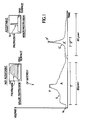
- FIG. 1 shows two sense signals which might be generated by a respective head/disk interference with two different disk protrusions, see insets (a), (b).
- each protrusion rises up from the disk surface and extends above the head flying height, H,H′.
- the sense signals are respectively shown as curves S, S′, each having a peak P, P′, duration T,T′, and area A, A′.
- Curve S is a representation of an HDI caused by a major disk protrusion -- inset (a) -- of sufficient character, in material density, breadth, mass, etc., to impede accurate use of the disk. This defect is unacceptable and is therefore desired to be detected.
- Curve S′ is a representation of an HDI caused by a minor disk protrusion -- inset (b) -- not having sufficient character to impede accurate use of the disk, although of sufficient height to impact with the head. This defect is acceptable and must be distinguished from the first protrusion.
- the system is shown to have a background noise level N.
- Fig. 1 The examples of Fig. 1 have been selected to show that the values of peaks P, P′ cannot be used to accurately discriminate between these two protrusions, although perhaps each peak tells something about the particular contact event. Even so, the areas A,A′ under the curves S,S′ are each a direct representation of the sensed energy of the respective HDI, and we believe that the sensed energy can be treated as a direct indicator of the severity of the interference. Hence, since these areas can be quantified, the HDIs can be easily evaluated.
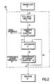
- our preferred Energy Head/Disk Interference (EHDI) surface protrusion detector 100 includes a full wave rectifier circuit 12; a candidate pre-qualifier circuit 14; an integrator circuit 16; and an interference of interest qualifier circuit 18.
- EHDI Energy Head/Disk Interference
- the full wave rectifier 12 receives sense signal S,S′ as output 20 from transducer 10 (associated with a test head flying over a disk of interest) and converts the signal to a positive rectified full wave signal 22.
- This signal 22 is then applied to candidate pre-qualifier circuit 14. If there are any rectified peaks on signal 22 which satisfy a noise threshold level 54 applied to qualifier circuit 14 (the noise threshold segment being set using a calibration disk), then a 20 ⁇ sec segment of the analog, rectified input signal is applied as candidate interference signal 24 from pre-qualifier 14 to integrator 16.
- the integrator integrates the candidate interference signal 24 and outputs an integrated signal 26.
- This signal 26 is the integral of signal 24 and is applied to qualifier 18.
- Qualifier 18 compares this integral (which expresses the area under the curve and represents the sensed HDI impact energy) with an impact energy threshold 70 (which is set using a calibration disk) to determine if an HDI of interest has occurred. If the voltage level of the integral satisfies the present energy threshold voltage level, then qualifier output signal 28 issues to enable interference register 30 to indicate detection of an interference of interest. The qualifier output 28 is also coupled back to reset integrator 16 and window timer 14B in anticipation of the next candidate interference signal 24, since a determination about the present candidate in the integrator has now been made.
- an interference signal from the transducer is qualified and quantified. If the filtered and rectified signal is above a given noise threshold, then it is pre-qualified as a candidate HDI for possible selection as an HDI of interest. If the integral of the candidate interference signal satisfies (e.g., at or above) the interference energy threshold, then it qualifies as an HDI of interest (i.e., an unacceptable impact event). Because we use and can set an impact energy threshold, we can also quantify the impact energy of an interference as being above a preset level. Furthermore, our discrimination process can be made from a single HDI reading.
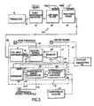
- a preferred embodiment 200 of the present invention is shown in Fig. 3, where the output 20 of transducer 10 (such as a piezoelectric or acoustic transducer) is coupled to the input of our EHDI detector 100 (at the input of full wave rectifier 12) via a high impedance amplifier 44 and a bandpass filter formed from a low pass filter 46 (-3db at 300 KHz) and a high pass filter 48 (-3db at 100 KHz).
- a bandpass filter formed from a low pass filter 46 (-3db at 300 KHz) and a high pass filter 48 (-3db at 100 KHz).
- the output signal 22 from rectifier 12 is applied to a first input of window enable comparator 14A of candidate pre-qualifier circuit 14.
- Noise threshold signal 54 (which we typically set at 20 ⁇ Volts) from noise threshold source 52 is applied to a second input of comparator 14a.
- Comparator 14A outputs input signal 22 if the input satisfies the noise threshold 54.
- Output 56 of comparator 14A is an analog signal from rectifier 12, and represents a pre-qualified candidate HDI of interest.
- Output 56 is applied to window timer circuit 14B, which is preferably a 10 ⁇ sec one-shot timer. The timer is triggered by and upon receipt of the output of comparator 14A.
- the output 24 of the window circuit is preferably a 20 ⁇ sec segment of the analog signal 56 from comparator 14A and is applied to a first input of integrator 16. This 20 ⁇ sec segment 24 is shown as analog signal 25.
- Window circuit 14B provides a fast rise and fall time at the leading and trailing edges, respectively, of segment 24. The fast rise time triggers integrator 16, which integrates the analog information on segment 24. The fast fall time resets the integrator at the end of the 20 ⁇ sec segment.
- the resulting integral (shown as waveform 66) represents the impact energy of the candidate HDI.
- the output 26 of the integrator is applied to a first input of interference energy comparator 18A of qualifier circuit 18.
- An interference energy threshold signal 70 from interference energy threshold source 68 is applied to a second input of interference energy comparator 18A. If the voltage of the candidate HDI signal, in the integral form of output 26, satisfies voltage level of threshold 70, then an interference indication signal 72 from compaator 18A is applied to interference of interest indicator 18B, which generates the interference of interest indication output signal 28 of qualifier 18.
- Interference indicator 18B is preferably a one-shot timer whose output is set according to circuit requirements, such as at 10 ⁇ sec; threshold signal 70 is typically 400 - 500 ⁇ V, normalized for a standard transducer -- such as piezoelectric or acoustic -- emission when calibrated with a calibrated disk.)
- a threshold voltage value 70 is set corresponding to the interference energy level of such a protrusion (by using a calibration disk). If the integrator output satisfies the impact energy threshold signal, then an interference detection signal causes the one shot-timer to generate an interference of interest indication signal. Selection of an actual limit to the height and breadth of an acceptable protrusion is an engineering decision, and is perhaps somewhat arbitrary, depending upon the particular head/disk operating requirements desired of a given system.
- the output 28 of indicator 18B is applied to the reset inputs of integrator 16 and of window timer 14B. This reset is appropriate since the present signal in the integrator has been qualified. This reset will prevent the same 20 ⁇ sec segment from being reintegrated.
- a side benefit of the integrator is that it averages out noise on signal 25 for higher reliability; also, test point 64 is provided so that the integral itself can be monitored so as to further study or quantify the HDI impact energy level, such as with a voltmeter, whether or not a particular candidate HDI qualifies further.
- Signal 28 as the output of EHDI detector 100, is applied to a first input of interference/sector correlator 80.
- Correlator 80 also receives sector pulse signals 84 (according to the number of sectors per revolution on the disk) from pulse source 82 so that the location of the qualified HDI can be recorded.
- Output 28 is also applied to interference counter 30, to tabulate qualified HDIs of interest.
- the integral Since the integral expresses the area under the voltage curve for a given interference reading, the integral can be used as a reliable measure of the seriousness of an interference, unlike peak reading. Since a single reading can be considered reliable, this reduces the burden of credence checking substantially.
- the invention does not require statistical averaging over several retries; however, use of such approach is not foreclosed.
- the invention is easily adapted to different products simply by changing transducers or disks or parameters such as acceptable protrusion height, frequency range, window duration, threshold level, etc.
Landscapes
- Physics & Mathematics (AREA)
- General Physics & Mathematics (AREA)
- Manufacturing Of Magnetic Record Carriers (AREA)
- Measurement Of Length, Angles, Or The Like Using Electric Or Magnetic Means (AREA)
- Air Bags (AREA)
Applications Claiming Priority (2)
| Application Number | Priority Date | Filing Date | Title |
|---|---|---|---|
| US07/372,673 US5168412A (en) | 1989-06-28 | 1989-06-28 | Surface interference detector |
| US372673 | 1989-06-28 |
Publications (2)
| Publication Number | Publication Date |
|---|---|
| EP0405740A2 true EP0405740A2 (de) | 1991-01-02 |
| EP0405740A3 EP0405740A3 (en) | 1992-04-08 |
Family
ID=23469183
Family Applications (1)
| Application Number | Title | Priority Date | Filing Date |
|---|---|---|---|
| EP19900305394 Ceased EP0405740A3 (en) | 1989-06-28 | 1990-05-18 | Surface interference detector |
Country Status (4)
| Country | Link |
|---|---|
| US (1) | US5168412A (de) |
| EP (1) | EP0405740A3 (de) |
| JP (1) | JPH0337504A (de) |
| CA (1) | CA2019874A1 (de) |
Families Citing this family (16)
| Publication number | Priority date | Publication date | Assignee | Title |
|---|---|---|---|---|
| US5488857A (en) * | 1991-11-22 | 1996-02-06 | Hitachi Electronic Engineering Co., Ltd. | Protrusion sensor for sensing protrusion on a disc |
| US5450747A (en) * | 1993-12-27 | 1995-09-19 | International Business Machines Corporation | Method for optimizing piezoelectric surface asperity detection sensor |
| US5539592A (en) * | 1994-10-05 | 1996-07-23 | International Business Machines Corporation | System and method for monitoring friction between head and disk to predict head disk interaction failure in direct access storage devices |
| US5668690A (en) * | 1996-04-29 | 1997-09-16 | Harrison; Joshua C. | Method and apparatus for lifetime prediction of gas lubricated interfaces in data storage devices |
| US5880587A (en) * | 1997-02-03 | 1999-03-09 | International Business Machines Corporation | Method and apparatus for performing in file slider take-off measurements through tuned external AE detection |
| US6100683A (en) * | 1997-07-14 | 2000-08-08 | Seagate Technology, Inc. | Drive in-situ head disc interference detection using standard deviation of read back signal frequency |
| US6239937B1 (en) * | 1997-09-22 | 2001-05-29 | Seagate Technology Llc | Adaptive last-track positioning scheme for hard-disk drive formatting |
| US6000282A (en) * | 1998-02-17 | 1999-12-14 | Seagate Technology, Inc. | System and method for uniform frequency response independent of slider contact location in glide tests |
| US6094973A (en) * | 1998-08-11 | 2000-08-01 | Seagate Technology, Inc. | Method and apparatus for mechanical screening of magnetic recording disk drives |
| US6785072B1 (en) * | 1999-07-23 | 2004-08-31 | Seagate Technology Llc | Disc drive stiction/friction characterization utilizing piezoelectric microactuators |
| US6281677B1 (en) * | 1999-11-04 | 2001-08-28 | International Business Machines Corporation | Method for defect marking and analysis of thin film hard disks |
| US6624892B1 (en) | 2000-06-01 | 2003-09-23 | Seagate Technolgy Llc | Method and apparatus for fly height testing using light emitting diodes |
| US6822821B2 (en) * | 2001-01-19 | 2004-11-23 | Seagate Technology Llc | Method and apparatus for predicting a head crash in a disc drive |
| JP4290638B2 (ja) * | 2004-11-18 | 2009-07-08 | 富士通株式会社 | ヘッドの寿命予測方法、記録媒体検査方法、ヘッドの評価方法、および情報記録再生装置 |
| US20070245814A1 (en) * | 2006-04-11 | 2007-10-25 | Kenichi Shitara | Magnetic disk defect test method, protrusion test device and glide tester |
| ITBO20110526A1 (it) * | 2011-09-14 | 2013-03-15 | Filippo Bastianini | Dispositivo a basso consumo per il monitoraggio continuativo a lungo termine della emissione acustica con registrazione di parametri peculiari ad essa relativi |
Family Cites Families (24)
| Publication number | Priority date | Publication date | Assignee | Title |
|---|---|---|---|---|
| US3536994A (en) * | 1968-03-28 | 1970-10-27 | Minnesota Mining & Mfg | Dropout counter with continuous integration and moving counting period |
| NL6812449A (de) * | 1968-08-31 | 1970-03-03 | ||
| GB1318701A (en) * | 1970-01-30 | 1973-05-31 | Rank Organisation Ltd | Methods of waveform analysis and apparatus therefor |
| US3761905A (en) * | 1971-08-20 | 1973-09-25 | Information Storage Systems | Disc pack defect detection system |
| DE2241263C3 (de) * | 1971-08-25 | 1975-05-07 | Hitachi Electronics Co., Ltd. | überwachungsvorrichtung zur Erfassung eines Fehlers auf der Oberfläche eines sich bewegenden bandförmigen Gegenstandes |
| BE790686A (nl) * | 1971-10-27 | 1973-04-27 | Hoogovens Ijmuiden Bv | Inrichting voor het optisch waarnemen van oppervlaktefouten aaneen voortlopende metalen band |
| DE2200222A1 (de) * | 1972-01-04 | 1973-07-12 | Ibm Deutschland | Vorrichtung zur bestimmung der oberflaechenguete |
| US4084324A (en) * | 1975-04-23 | 1978-04-18 | The Rank Organisation Limited | Measuring instrument |
| US4030830A (en) * | 1976-01-05 | 1977-06-21 | Atlantic Research Corporation | Process and apparatus for sensing defects on a smooth surface |
| US4358738A (en) * | 1976-06-07 | 1982-11-09 | Kahn Leonard R | Signal presence determination method for use in a contaminated medium |
| US4126036A (en) * | 1977-07-27 | 1978-11-21 | United States Steel Corporation | Surface roughness analyzer |
| JPS54145566A (en) * | 1978-05-04 | 1979-11-13 | Matsushita Electric Ind Co Ltd | Surface roughness measuring method using magnetic recording method |
| US4213331A (en) * | 1978-12-20 | 1980-07-22 | The B. F. Goodrich Company | Surface irregularity analyzer |
| US4452534A (en) * | 1981-09-01 | 1984-06-05 | Gribanov Dmitry D | Method of determining geometric parameters of object's surface and device therefor |
| DE3238077A1 (de) * | 1982-10-14 | 1984-04-19 | Basf Ag, 6700 Ludwigshafen | Verfahren und schaltungsanordnungen zum auffinden und auswerten von fehlstellen auf aufzeichnungstraegern mit in wenigstens einer spur aufgezeichneten digitalsignalen |
| US4541070A (en) * | 1982-11-04 | 1985-09-10 | Musin Rafail M | Pulse characteristic meter |
| US4532802A (en) * | 1984-05-31 | 1985-08-06 | International Business Machines Corporation | Apparatus for analyzing the interface between a recording disk and a read-write head |
| US4669011A (en) * | 1985-05-03 | 1987-05-26 | Eastman Kodak Company | Slider assembly with dynamically positionable transducer |
| US4635139A (en) * | 1985-08-26 | 1987-01-06 | International Business Machines Corporation | Asperity burst writer |
| JPS62173614A (ja) * | 1986-01-28 | 1987-07-30 | Matsushita Electric Ind Co Ltd | ヘツド目詰まり検出装置 |
| JPS62195511A (ja) * | 1986-02-24 | 1987-08-28 | Hitachi Maxell Ltd | 磁気デイスク欠陥検出装置 |
| DE3669060D1 (de) * | 1986-04-04 | 1990-03-22 | Ibm Deutschland | Arbeitsueberwachungsverfahren einer kopfplattentrennflaeche und geraet zum verhindern von datenverlusten infolge von kopfplatteninterferenzen. |
| JPH0777062B2 (ja) * | 1986-10-30 | 1995-08-16 | 日本電信電話株式会社 | ヘツド・媒体接触検出装置 |
| US4812927A (en) * | 1987-11-05 | 1989-03-14 | Storage Technology Corporation | Head-to-disk interference detector |
-
1989
- 1989-06-28 US US07/372,673 patent/US5168412A/en not_active Expired - Lifetime
-
1990
- 1990-05-18 EP EP19900305394 patent/EP0405740A3/en not_active Ceased
- 1990-06-19 JP JP2161184A patent/JPH0337504A/ja active Pending
- 1990-06-26 CA CA002019874A patent/CA2019874A1/en not_active Abandoned
Also Published As
| Publication number | Publication date |
|---|---|
| JPH0337504A (ja) | 1991-02-18 |
| EP0405740A3 (en) | 1992-04-08 |
| CA2019874A1 (en) | 1990-12-28 |
| US5168412A (en) | 1992-12-01 |
Similar Documents
| Publication | Publication Date | Title |
|---|---|---|
| US5168412A (en) | Surface interference detector | |
| EP0467615B1 (de) | Magnetisches Speichersystem und Betriebsweise | |
| EP0294761B1 (de) | Verfahren und Vorrichtung zur Vermeidung eines Stosses des magnetischen Wandlers auf das Magnetsubstrat | |
| US6008640A (en) | Detection and measurement of head disc interference using read back signal (without acoustic emission sensor or laser doppler vibrometer) | |
| WO1995032412A1 (en) | System and method for testing the integrity of porous elements | |
| US5792947A (en) | Method and apparatus for combined glide and defect analysis | |
| JPH0237542B2 (de) | ||
| US5419176A (en) | Particle detection and analysis | |
| EP0667954A1 (de) | Vorrichtung und verfahren zum testen der integrität poröser elemente | |
| US7369341B2 (en) | Head flying height measuring apparatus in magnetic storage device | |
| JP2021073459A (ja) | 打音検査装置及び打音検査方法 | |
| JP4243911B2 (ja) | 磁気媒体転写品質の管理装置 | |
| US4638446A (en) | Apparatus and method for reducing topographical effects in an auger image | |
| US6021666A (en) | Determining a close point for glide heads | |
| US7671607B2 (en) | System and method for measuring air bearing gap distance | |
| JP6989375B2 (ja) | ラジアルゲートの支承部材としてのゲートピン検査装置および検査方法 | |
| US7684951B2 (en) | Method and device for detecting a pulse-type mechanical effect on a system part | |
| JPS6110768A (ja) | 自動式超音波試験におけるダミ−表示の抑圧方法 | |
| JPS5940268B2 (ja) | アコ−スティック・エミッション信号検出感度検査方法及び装置 | |
| KR100961993B1 (ko) | 광역 관찰창을 이용한 활성화 신호 검출 방법, 그 장치 및이를 기록한 기록매체 | |
| JPH06258300A (ja) | 超音波探傷の異常信号抽出装置および該異常信号の抽出方法 | |
| JP2002071447A (ja) | パルス音判定方法 | |
| JPS5987357A (ja) | 圧力容器内音源位置標定装置 | |
| RU2687177C1 (ru) | Способ обнаружения и классификации сигнала в системах контроля | |
| Ogawa et al. | A method for predicting missing-error counts at high recording densities |
Legal Events
| Date | Code | Title | Description |
|---|---|---|---|
| PUAI | Public reference made under article 153(3) epc to a published international application that has entered the european phase |
Free format text: ORIGINAL CODE: 0009012 |
|
| 17P | Request for examination filed |
Effective date: 19900601 |
|
| AK | Designated contracting states |
Kind code of ref document: A2 Designated state(s): AT BE CH DE DK ES FR GB GR IT LI LU NL SE |
|
| PUAL | Search report despatched |
Free format text: ORIGINAL CODE: 0009013 |
|
| AK | Designated contracting states |
Kind code of ref document: A3 Designated state(s): AT BE CH DE DK ES FR GB GR IT LI LU NL SE |
|
| 17Q | First examination report despatched |
Effective date: 19930330 |
|
| STAA | Information on the status of an ep patent application or granted ep patent |
Free format text: STATUS: THE APPLICATION HAS BEEN REFUSED |
|
| 18R | Application refused |
Effective date: 19940901 |