EP0405132A1 - Winkelaufsatz - Google Patents
Winkelaufsatz Download PDFInfo
- Publication number
- EP0405132A1 EP0405132A1 EP90109556A EP90109556A EP0405132A1 EP 0405132 A1 EP0405132 A1 EP 0405132A1 EP 90109556 A EP90109556 A EP 90109556A EP 90109556 A EP90109556 A EP 90109556A EP 0405132 A1 EP0405132 A1 EP 0405132A1
- Authority
- EP
- European Patent Office
- Prior art keywords
- drill
- rays
- attachment according
- permeable
- attachment
- Prior art date
- Legal status (The legal status is an assumption and is not a legal conclusion. Google has not performed a legal analysis and makes no representation as to the accuracy of the status listed.)
- Granted
Links
Images
Classifications
-
- B—PERFORMING OPERATIONS; TRANSPORTING
- B23—MACHINE TOOLS; METAL-WORKING NOT OTHERWISE PROVIDED FOR
- B23Q—DETAILS, COMPONENTS, OR ACCESSORIES FOR MACHINE TOOLS, e.g. ARRANGEMENTS FOR COPYING OR CONTROLLING; MACHINE TOOLS IN GENERAL CHARACTERISED BY THE CONSTRUCTION OF PARTICULAR DETAILS OR COMPONENTS; COMBINATIONS OR ASSOCIATIONS OF METAL-WORKING MACHINES, NOT DIRECTED TO A PARTICULAR RESULT
- B23Q5/00—Driving or feeding mechanisms; Control arrangements therefor
- B23Q5/02—Driving main working members
- B23Q5/04—Driving main working members rotary shafts, e.g. working-spindles
- B23Q5/043—Accessories for spindle drives
- B23Q5/045—Angle drives
-
- A—HUMAN NECESSITIES
- A61—MEDICAL OR VETERINARY SCIENCE; HYGIENE
- A61B—DIAGNOSIS; SURGERY; IDENTIFICATION
- A61B17/00—Surgical instruments, devices or methods, e.g. tourniquets
- A61B17/16—Bone cutting, breaking or removal means other than saws, e.g. Osteoclasts; Drills or chisels for bones; Trepans
- A61B17/17—Guides or aligning means for drills, mills, pins or wires
- A61B17/1703—Guides or aligning means for drills, mills, pins or wires using imaging means, e.g. by X-rays
-
- A—HUMAN NECESSITIES
- A61—MEDICAL OR VETERINARY SCIENCE; HYGIENE
- A61B—DIAGNOSIS; SURGERY; IDENTIFICATION
- A61B17/00—Surgical instruments, devices or methods, e.g. tourniquets
- A61B17/16—Bone cutting, breaking or removal means other than saws, e.g. Osteoclasts; Drills or chisels for bones; Trepans
- A61B17/17—Guides or aligning means for drills, mills, pins or wires
- A61B17/1739—Guides or aligning means for drills, mills, pins or wires specially adapted for particular parts of the body
- A61B17/1742—Guides or aligning means for drills, mills, pins or wires specially adapted for particular parts of the body for the hip
-
- A—HUMAN NECESSITIES
- A61—MEDICAL OR VETERINARY SCIENCE; HYGIENE
- A61B—DIAGNOSIS; SURGERY; IDENTIFICATION
- A61B17/00—Surgical instruments, devices or methods, e.g. tourniquets
- A61B17/16—Bone cutting, breaking or removal means other than saws, e.g. Osteoclasts; Drills or chisels for bones; Trepans
- A61B17/17—Guides or aligning means for drills, mills, pins or wires
- A61B17/1739—Guides or aligning means for drills, mills, pins or wires specially adapted for particular parts of the body
- A61B17/1757—Guides or aligning means for drills, mills, pins or wires specially adapted for particular parts of the body for the spine
-
- A—HUMAN NECESSITIES
- A61—MEDICAL OR VETERINARY SCIENCE; HYGIENE
- A61B—DIAGNOSIS; SURGERY; IDENTIFICATION
- A61B17/00—Surgical instruments, devices or methods, e.g. tourniquets
- A61B2017/00831—Material properties
- A61B2017/00902—Material properties transparent or translucent
Definitions
- the invention relates to an angle attachment for a drilling machine according to the preamble of claim 1.
- a further improvement of this technique could be achieved through the use of various target devices to be introduced into the beam path, which serve to check the position and the drilling direction of the drill during the operation and to change it in a controlled manner.
- target devices to be introduced into the beam path, which serve to check the position and the drilling direction of the drill during the operation and to change it in a controlled manner.
- target device is described for example in EP-A-0 201 737.
- the invention seeks to remedy this.
- the invention has for its object to provide an angle attachment for a drill which is permeable to X-rays, so that only the drill is visible in the image intensifier and the position of the drill and its drilling direction can be continuously checked and corrected if necessary while maintaining a normal radiation intensity.
- the invention solves the problem with an angle attachment, which has the features of claim 1.
- the advantages achieved by the invention are essentially to be seen in the fact that, thanks to the angular attachment according to the invention, the surgeon can work unimpeded under the image converter control.
- the operating field that is visible on the screen under X-ray radiation is not covered or darkened as in the case of devices according to the prior art.
- Another advantage results from the fact that most of the image intensifiers used in the operating room have an automatic radiation metering device; this automatic system determines the minimum radiation dose required to penetrate the "object" in the radiation field. If there are metallic parts (e.g. a commercial drill) in the radiation field, the automatic of the image intensifier tries to penetrate them. The resulting increase in radiation is massive and puts a strain on both the surgeon and the patient.
- the so-called scattered radiation places an additional burden on the surgeon.
- This scattered radiation occurs primarily through reflection of the primary radiation by radiation-opaque objects. It is therefore a further advantage of the invention that the scattered radiation can be reduced to a minimum. Since the drill used itself is made of metal, ie is opaque to radiation, it is clearly visible on the image intensifier screen. Thanks to the invention, the positioning of the drill tip and the drill direction can thus be continuously checked and, if necessary, corrected without any disruptive effects.
- the position of the detachable angular attachment housing can be selected such that the surgeon's hand is outside the beam path of the image intensifier.
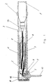
- the angular attachment shown in FIG. 1 essentially consists of the actual angular gear 7, 8, 9, which is accommodated in a housing 4 that can be coupled to the drilling machine 1. All parts of the angle attachment, with the exception of the locking ring 2, which is used for coupling to the drilling machine 1, and the shaft-like coupling 3, are made of an X-ray transparent material.
- Polyaether ether ketones (PEEK), polyamide imides (eg TORLON) and polyoxymethylene (POM) have proven to be suitable materials. These materials are not only radiolucent, but also self-lubricating and sterilizable up to 140 ° C, which is very important for the intended use.
- X-ray transparent composite plastics which can preferably be fiber, fabric or ball reinforced, as well as special ceramic materials can be used.
- the mechanical function of the actual angular gear 7, 8, 9 is otherwise entirely conventional.
- the rotary drive of the drilling machine 1 is transmitted to the drive shaft 7 of the angle attachment via the shaft-like coupling 3, which can be fastened in the chuck 13 of the drilling machine 1.
- the drive shaft 7 is accommodated in a bearing cage 6 which has a front and a rear bearing 5 for the drive shaft 7. Instead of the two annular bearings 5, the drive shaft 7 can also be designed as a plain bearing.
- the drive shaft 7 carries at its front end a tapered bearing 8, which corresponds to a second tapered bearing 9 arranged at a 90 ° angle, which in turn drives the drill 10.
- the tapered bearing 9 can either be fixedly connected to the drill 10 or connected to it by means of a suitable coupling (not shown).
- the drive shaft 7 is additionally stabilized by a coaxial support bolt 12.
- this support bolt 12 is not absolutely necessary and can be replaced by an extension (not shown) of the drill 10 used up to the housing cover 11.
- a hollow drill can be used if drilling has to be done using a wire.
- the razor wire has the function of a probe that is optimally placed after possibly several attempts and guides the drill 10 during the actual drilling process. This drilling technique is applied, for example, to the spine or the pelvis sends where the placement of bone screws must be carried out extremely precisely. Despite being guided through the wire, the drilling process is carried out under image intensifier control; the reason for this is the risk of advancing the razor wire and the lateral penetration of the drill 10 out of the bone.
- the X-ray permeability of the angle attachment is extremely helpful because it does not obscure or overexpose the image intensifier image, so that the vertebral body to be drilled remains clearly visible and the drilling process remains controllable.
Landscapes
- Health & Medical Sciences (AREA)
- Engineering & Computer Science (AREA)
- Life Sciences & Earth Sciences (AREA)
- Nuclear Medicine, Radiotherapy & Molecular Imaging (AREA)
- Surgery (AREA)
- Radiology & Medical Imaging (AREA)
- Heart & Thoracic Surgery (AREA)
- Oral & Maxillofacial Surgery (AREA)
- Orthopedic Medicine & Surgery (AREA)
- Pathology (AREA)
- Mechanical Engineering (AREA)
- Biomedical Technology (AREA)
- Dentistry (AREA)
- Medical Informatics (AREA)
- Molecular Biology (AREA)
- Animal Behavior & Ethology (AREA)
- General Health & Medical Sciences (AREA)
- Public Health (AREA)
- Veterinary Medicine (AREA)
- Surgical Instruments (AREA)
Abstract
Description
- Die Erfindung bezieht sich auf einen Winkelaufsatz für eine Bohrmaschine gemäss dem Oberbegriff des Anspruchs 1.
- Bei einer Vielzahl von osteosynthetischen Verfahren in der Chirurgie werden Bohrmaschinen verwendet, insbesondere um Gewindebohrungen für Knochenschrauben anzubringen und für die Markraumbohrung. Bei letzterer muss jedoch wegen der anatomisch-geometrischen Verhältnisse zusätzlich ein an die Bohrmaschine kuppelbares Winkelgetriebe benutzt werden.
Solche als Winkelaufsätze konzipierte Winkelgetriebe sind schon seit längerer Zeit bekannt und im Handel (beispielsweise unter der Marke SYNTHES) erhältlich.
Um die Genauigkeit der mittels solcher Bohrmaschinen (mit oder ohne Winkelaufsatz) plazierter Bohrungen zu verbessern, wurde in den letzten Jahren eine Technik entwickelt, bei welcher der Knochen im Strahlengang eines Röntgengerätes unter Bildverstärkerkontrolle bearbeitet wird. Eine weitere Verbesserung dieser Technik konnte durch den Einsatz diverser in den Strahlengang einzubringender Zielgeräte erreicht werden, welche dazu dienen während des Operationsvorganges die Position und die Bohrrichtung des Bohrers zu überprüfen und in kontrollierter Weise zu verändern. Ein solches Zielgerät ist beispielsweise in der EP-A-0 201 737 beschrieben. - Allen diesen Zielgeräten haftet jedoch der Nachteil an, dass ihre Position während des eigentlichen Bohrvorganges nicht kontrolliert werden kann, weil die Bohrmaschine das Sichtfeld des Bildverstärkers verdeckt. Diese Abdeckung des Gesichtsfeldes hat noch den weiteren Nachteil, dass die automatisch erfolgende Strahlendosierung am Bildverstärker die Strahlenintensität erhöht, um das Metall der Bohrmaschine zu durchdringen. Die nun um einiges erhöhte Strahlenintensität trifft natürlich auch die Hand des Chirurgen, der die Bohrmaschine führen muss. Von besonderer Gefährlichkeit ist dabei die durch Reflexion am Metall auftretende Sekundärstrahlung.
Durch die höhere Strahlenintensität ergibt sich bei konventionellen Zielgeräten der oben beschriebenen Art auch noch ein weiterer Nachteil, indem jene Stellen im erzeugten Bild, auf die es klinisch wirklich ankommt, nicht mehr zu sehen sind. - Hier will die Erfindung Abhilfe schaffen. Der Erfindung liegt die Aufgabe zugrunde, einen Winkelaufsatz für eine Bohrmaschine zu schaffen, welcher röntgenstrahlendurchlässig ist, so dass lediglich der Bohrer im Bildverstärker sichtbar wird und dadurch die Position des Bohrers und dessen Bohrrichtung laufend überprüft und gegebenenfalls korrigiert werden kann unter Beibehaltung einer normalen Strahlenintensität.
- Die Erfindung löst die gestellte Aufgabe mit einem Winkelaufsatz, welcher die Merkmale des Anspruchs 1 aufweist.
- Die durch die Erfindung erreichten Vorteile sind im wesentlichen darin zu sehen, dass dank des erfindungsgemässen Winkelaufsatzes der Chirurg unbehindert unter Bildwandler-Kontrolle arbeiten kann. Das unter Röntgenbestrahlung auf dem Bildschirm sichtbare Operationsfeld wird nicht wie bei Geräten nach dem Stand der Technik abgedeckt oder abgedunkelt.
Ein weiterer Vorteil ergibt sich durch den Umstand, dass die meisten im Operationssaal verwendeten Bildverstärker eine automatische Strahlungsdosier-Vorrichtung besitzen; diese Automatik ermittelt die minimal benötigte Strahlendosis, die benötigt wird, um das im Strahlenfeld befindliche "Objekt" zu durchdringen. Befinden sich nun metallische Teile (z.B. eine handelsübliche Bohrmaschine) im Strahlenfeld, versucht die Automatik des Bildverstärkers diese zu durchdringen. Die daraus resultierende Strahlenerhöhung ist massiv und belastet sowohl den Chirurgen wie auch den Patienten.
Neben der direkten Strahlenbelastung im unmittelbaren Strahlengang bewirkt die sogenannte Streustrahlung eine zusätzliche Belastung für den Chirurgen. Diese Streustrahlung tritt vor allem durch Reflexion der Primärstrahlung durch strahlenundurchlässige Objekte auf. Es ist deshalb ein weiterer Vorteil der Erfindung, dass dadurch die Streustrahlung auf ein Minimum reduziert werden kann.
Da der verwendete Bohrer selber aus Metall besteht, d.h. strahlenundurchlässig ist, wird er auf dem Bildschirm des Bildverstärkers deutlich sichbar. Dank der Erfindung kann somit ohne störende Effekte laufend die Positionierung der Bohrerspitze und die Bohrerrichtung kontrolliert und gegebenenfalls korrigiert werden. - Bei der bevorzugten 90°-Anordnung des erfindungsgemässen Winkelaufsatzes ergibt sich ein weiterer Vorteil, wegen seiner guten Handhabbarkeit im eingeschränkten Raum zwischen Patient und dem Bildverstärker-Empfänger; zudem kann die Lage des kuppelbaren Winkelaufsatz-Gehäuses so gewählt werden, dass sich die Hand des Chirurgen ausserhalb des Strahlenganges des Bildverstärkers befindet.
- Ein Ausführungsbeispiel der Erfindung, welches zugleich das Funktionsprinzip erläutert, ist in der Zeichnung dargestellt und wird im folgenden näher beschrieben.
- Fig. 1 stellt einen Längsschnitt durch den erfindungsgemäss Winkelaufsatz dar.
- Der in Fig. 1 dargestellte Winkelaufsatz besteht im wesentlichen aus dem eigentlichen Winkelgetriebe 7,8,9, welches in einem an die Bohrmaschine 1 kuppelbaren Gehäuse 4 untergebracht ist. Sämtliche Teile des Winkelaufsatzes, mit Ausnahme des zur Kupplung an die Bohrmaschine 1 dienenden Sperringes 2 und die wellenartige Kupplung 3, sind aus einem röntgenstrahlendurchlässigen Material gefertigt. Als dazu geeignete Materialien haben sich insbesondere Polyaetheraetherketone (PEEK), Polyamidimide (z.B. TORLON) und Polyoxymethylen (POM) erwiesen. Diese Materialien sind nicht nur röntgenstrahlendurchlässig, sondern auch selbstschmierend und bis 140 °C sterilisierbar, was für den vorgesehenen Verwendungszweck von grosser Wichtigkeit ist. Auch röntgenstrahlendurchlässige Komposit-Kunststoffe, welche vorzugsweise faser-, gewebe- oder kugelverstärkt sein können, sowie spezielle keramische Werkstoffe können eingesetzt werden.
- Die mechanische Funktion des eigentlichen Winkelgetriebes 7,8,9 ist im übrigen durchwegs konventionell. Der rotative Antrieb der Bohrmaschine 1 wird über die wellenartige Kupplung 3, welche im Spannfutter 13 der Bohrmaschine 1 befestigbar ist, auf die Antriebswelle 7 des Winkelaufsatzes übertragen. Die Antriebswelle 7 ist in einem Lagerkäfig 6 untergebracht, welcher ein vorderes und ein hinteres Lager 5 für die Antriebswelle 7 aufweist. Statt der beiden ringförmigen Lager 5 kann die Antriebswelle 7 auch als Gleitlager ausgebildet sein.
Die Antriebswelle 7 trägt an ihrem vorderen Ende ein Kegellager 8, welches mit einem im 90°-Winkel angeordneten zweiten Kegellager 9 korrespondiert, welches seinerseits den Bohrer 10 antreibt. Das Kegellager 9 kann entweder fest mit dem Bohrer 10 verbunden sein oder damit mittels einer (nicht dargestellten) geeigneten Kupplung verbunden sein.
Die Antriebswelle 7 wird zusätzlich durch einen koaxialen Abstützbolzen 12 stabilisiert. Dieser Abstützbolzen 12 ist jedoch nicht unbedingt erforderlich und kann durch eine (nicht dargestellte) Verlängerung des eingesetzten Bohrers 10 bis zum Gehäusedeckel 11 ersetzt werden. Bei dieser Variante kann ein hohler Bohrer verwendet werden, wenn eine Bohrung über einen Spickdraht zu erfolgen hat. Der Spickdraht hat die Funktion einer Sonde, die nach eventuell mehreren Versuchen optimal plaziert wird und den Bohrer 10 beim eigentlichen Bohrvorgang führt. Diese Bohrtechnik wird, z.B. an der Wirbelsäule oder am Becken ange sendet, wo das Setzen von Knochenschrauben ausserordentlich präzise durchgeführt werden muss. Trotz der Führung durch den Spickdraht, wird der Aufbohrvorgang unter Bildverstärkerkontrolle durchgeführt; der Grund dafür ist die Gefahr des Vorschiebens des Spickdrahtes und die seitliche Penetration des Bohrers 10 aus dem Knochen. Bei diesem Bohrvorgang, insbesondere an der Wirbelsäule, ist die Röntgenstrahlendurchlässigkeit des Winkelaufsatzes ausserordentlich hilfreich, weil damit keine Verdunkelung oder Überstrahlung des Bildverstärker-Bildes erfolgt, so dass einerseits der zu bohrende Wirbelkörper gut sichtbar bleibt und anderseits der Bohrvorgang kontrollierbar bleibt.
Claims (10)
Applications Claiming Priority (2)
| Application Number | Priority Date | Filing Date | Title |
|---|---|---|---|
| CH2222/89A CH678804A5 (de) | 1989-06-14 | 1989-06-14 | |
| CH222/89 | 1989-06-14 |
Publications (2)
| Publication Number | Publication Date |
|---|---|
| EP0405132A1 true EP0405132A1 (de) | 1991-01-02 |
| EP0405132B1 EP0405132B1 (de) | 1994-09-07 |
Family
ID=4228721
Family Applications (1)
| Application Number | Title | Priority Date | Filing Date |
|---|---|---|---|
| EP90109556A Expired - Lifetime EP0405132B1 (de) | 1989-06-14 | 1990-05-19 | Winkelaufsatz |
Country Status (4)
| Country | Link |
|---|---|
| US (1) | US5041119A (de) |
| EP (1) | EP0405132B1 (de) |
| CH (1) | CH678804A5 (de) |
| DE (1) | DE59007033D1 (de) |
Cited By (13)
| Publication number | Priority date | Publication date | Assignee | Title |
|---|---|---|---|---|
| EP0441602A1 (de) * | 1990-02-07 | 1991-08-14 | SMITH & NEPHEW RICHARDS, INC. | Führungssystem für chirurgisches Instrument |
| EP0491149A1 (de) * | 1990-12-19 | 1992-06-24 | Synthes AG, Chur | Bohrfutter für eine insbesondere chirurgischen Zwecken dienende Bohrmaschine |
| WO1992017709A1 (en) * | 1991-04-08 | 1992-10-15 | The Torrington Company | Polymer bearing cage with amorphous case |
| US5182070A (en) * | 1991-04-08 | 1993-01-26 | The Torrington Company | Process for molding polymer bearing cage with amorphous case |
| US5223203A (en) * | 1991-04-08 | 1993-06-29 | The Torrington Company | Method for making a polymer part having an amorphous surface layer |
| EP0563585A1 (de) * | 1992-04-01 | 1993-10-06 | Imt Integral Medizintechnik Ag | Knochenraspel aus Kunststoff |
| AU651958B2 (en) * | 1990-02-07 | 1994-08-11 | Smith & Nephew, Inc. | Surgical instrument |
| US5478343A (en) * | 1991-06-13 | 1995-12-26 | Howmedica International, Inc. | Targeting device for bone nails |
| US6214013B1 (en) | 1997-12-19 | 2001-04-10 | Stryker Technologies Corporation | Method of using a guide-pin placement device |
| US8795287B2 (en) | 2007-02-08 | 2014-08-05 | Zimmer, Inc. | Targeting device |
| WO2017097951A1 (en) * | 2015-12-11 | 2017-06-15 | Atlas Copco Industrial Technique Ab | Power wrench with angle drive |
| EP1871273B1 (de) * | 2005-03-09 | 2018-10-03 | Kaltenbach & Voigt GmbH | Medizinisches oder dentalmedizinisches handstück |
| CN109875640A (zh) * | 2019-03-20 | 2019-06-14 | 广西医科大学第一附属医院 | 一种操作角度可变和不遮挡影像视野的关节突骨凿 |
Families Citing this family (29)
| Publication number | Priority date | Publication date | Assignee | Title |
|---|---|---|---|---|
| US5391170A (en) * | 1991-12-13 | 1995-02-21 | David A. McGuire | Angled surgical screw driver and methods of arthroscopic ligament reconstruction |
| US5464407A (en) * | 1991-02-19 | 1995-11-07 | Mcguire; David A. | Flexible surgical screwdriver and methods of arthroscopic ligament reconstruction |
| US5785709A (en) * | 1993-05-10 | 1998-07-28 | Hospital For Joint Diseases Orthopaedic Institute | Apparatus and method for performing a surgical procedure on bone lesions |
| US5927976A (en) * | 1996-05-10 | 1999-07-27 | Cyberdent, Inc. | Medication injection device and method |
| DE19624181C2 (de) * | 1996-06-18 | 2003-07-03 | Winter & Ibe Olympus | Chirurgisches Schaftinstrument |
| AU9122498A (en) | 1997-09-05 | 1999-03-29 | Board Of Regents, The University Of Texas System | Creating holes in bone via the medullary cavity |
| US7331963B2 (en) * | 1997-10-06 | 2008-02-19 | Warsaw Orthopedic, Inc. | Drill head for use in placing an intervertebral disc device |
| US5928239A (en) * | 1998-03-16 | 1999-07-27 | University Of Washington | Percutaneous surgical cavitation device and method |
| EP1681021A3 (de) * | 1998-06-09 | 2009-04-15 | Warsaw Orthopedic, Inc. | Schleifelement zur Vorbereitung eines Raums zwischen gegenüberliegenden Wirbeln |
| US6309394B1 (en) * | 1998-08-20 | 2001-10-30 | Volunteers For Medical Engineering | Bone cutting and breaking apparatus, and miniaturized cutting head |
| US6048260A (en) | 1999-07-01 | 2000-04-11 | Roto-Zip Tool Corporation | Angle attachment for power tool |
| WO2001050973A1 (en) * | 1999-12-24 | 2001-07-19 | Lee Hee Young | Mandibular angle fracture operating method and its devices |
| US6679886B2 (en) | 2000-09-01 | 2004-01-20 | Synthes (Usa) | Tools and methods for creating cavities in bone |
| US6692501B2 (en) * | 2000-12-14 | 2004-02-17 | Gary K. Michelson | Spinal interspace shaper |
| US6562045B2 (en) * | 2001-02-13 | 2003-05-13 | Sdgi Holdings, Inc. | Machining apparatus |
| US20040158254A1 (en) * | 2003-02-12 | 2004-08-12 | Sdgi Holdings, Inc. | Instrument and method for milling a path into bone |
| US7077736B2 (en) | 2003-03-03 | 2006-07-18 | Credo Technology Corporation | Angle attachment for power tool |
| US20050043739A1 (en) * | 2003-08-18 | 2005-02-24 | Sullivan Robert L. | Hybrid flexible drive shaft |
| US8398639B2 (en) * | 2005-09-29 | 2013-03-19 | Symmetry Medical Manufacturing, Inc. | Minimally invasive surgical driver |
| US8480673B2 (en) * | 2006-06-01 | 2013-07-09 | Osteo Innovations Llc | Cavity creation device and methods of use |
| MX2009010707A (es) * | 2007-04-04 | 2010-03-26 | Alexandria Res Technologies Llc | Aparato y metodo para esculpir la superficie de una articulacion. |
| US20090088770A1 (en) * | 2007-10-01 | 2009-04-02 | Warsaw Orthopedic, Inc. | Angled surgical drivers and methods of use |
| US8366719B2 (en) | 2009-03-18 | 2013-02-05 | Integrated Spinal Concepts, Inc. | Image-guided minimal-step placement of screw into bone |
| DE102009031269B4 (de) * | 2009-06-30 | 2013-07-25 | Universität Rostock | Vorrichtung zur In-situ-Fräsung von Gelenkflächen |
| EP2451408B1 (de) * | 2009-07-10 | 2023-09-06 | Implantica Patent Ltd. | Hüftgelenksinstrument |
| EP2451365B1 (de) * | 2009-07-10 | 2015-07-01 | Kirk Promotion LTD. | Hüftgelenkinstrument |
| TWI579007B (zh) | 2010-07-02 | 2017-04-21 | 艾格諾福斯保健公司 | 骨再生材料之用途 |
| KR101466747B1 (ko) * | 2013-09-27 | 2014-11-28 | 주의탁 | 견봉성형술용 천공 장치 |
| CN113414429B (zh) * | 2021-07-08 | 2022-06-10 | 西安石油大学 | 一种石油射孔枪内盲孔加工装置 |
Citations (7)
| Publication number | Priority date | Publication date | Assignee | Title |
|---|---|---|---|---|
| DE2300120A1 (de) * | 1971-11-10 | 1974-07-04 | Dotco Inc | Winkelfoermige antriebsvorrichtung fuer werkzeuge od.dgl |
| US4072084A (en) * | 1976-12-17 | 1978-02-07 | The United States Of America As Represented By The United States Department Of Energy | Graphite fiber reinforced structure for supporting machine tools |
| WO1984001099A1 (en) * | 1982-09-21 | 1984-03-29 | Buermoos Dentalwerk | Bent part for dentist |
| EP0253526A1 (de) * | 1986-06-27 | 1988-01-20 | DiPietropolo, Al | Flexible Reibahle für Knochenmark |
| US4722336A (en) * | 1985-01-25 | 1988-02-02 | Michael Kim | Placement guide |
| EP0296872A2 (de) * | 1987-06-25 | 1988-12-28 | Surgical Dynamics, Inc. | Rahmengestell zum Halten von chirurgischen Instrumenten an einer chirurgischen Wunde |
| US4808185A (en) * | 1986-02-07 | 1989-02-28 | Penenberg Brad L | Tibial prosthesis, template and reamer |
Family Cites Families (9)
| Publication number | Priority date | Publication date | Assignee | Title |
|---|---|---|---|---|
| US3704707A (en) * | 1971-04-06 | 1972-12-05 | William X Halloran | Orthopedic drill guide apparatus |
| US3867943A (en) * | 1972-09-13 | 1975-02-25 | Weck & Co Edward | Surgical drill with detachable hand-piece |
| US4257411A (en) * | 1979-02-08 | 1981-03-24 | Cho Kenneth O | Cruciate ligament surgical drill guide |
| DE8208970U1 (de) * | 1982-03-30 | 1982-09-09 | Howmedica International, Inc. Zweigniederlassung Kiel, 2301 Schönkirchen | Distales Zielgerät für einen Verriegelungsnagel |
| US4522201A (en) * | 1983-04-14 | 1985-06-11 | Tongue John R | Orthopedic surgery drill guide apparatus |
| DE8417428U1 (de) * | 1984-06-08 | 1984-09-13 | Howmedica International, Inc. Zweigniederlassung Kiel, 2300 Kiel | Zielgerät |
| US4917111A (en) * | 1987-10-15 | 1990-04-17 | Dietmar Pennig | Instrument for aiming and hole forming for implantation of locking nails of the like |
| US4848327A (en) * | 1988-05-23 | 1989-07-18 | Perdue Kevin D | Apparatus and procedure for blind alignment of fasteners extended through transverse holes in an orthopedic locking nail |
| US4901711A (en) * | 1988-12-27 | 1990-02-20 | Marlowe Goble E | Drill guide |
-
1989
- 1989-06-14 CH CH2222/89A patent/CH678804A5/de not_active IP Right Cessation
- 1989-12-05 US US07/446,041 patent/US5041119A/en not_active Expired - Lifetime
-
1990
- 1990-05-19 EP EP90109556A patent/EP0405132B1/de not_active Expired - Lifetime
- 1990-05-19 DE DE59007033T patent/DE59007033D1/de not_active Expired - Lifetime
Patent Citations (7)
| Publication number | Priority date | Publication date | Assignee | Title |
|---|---|---|---|---|
| DE2300120A1 (de) * | 1971-11-10 | 1974-07-04 | Dotco Inc | Winkelfoermige antriebsvorrichtung fuer werkzeuge od.dgl |
| US4072084A (en) * | 1976-12-17 | 1978-02-07 | The United States Of America As Represented By The United States Department Of Energy | Graphite fiber reinforced structure for supporting machine tools |
| WO1984001099A1 (en) * | 1982-09-21 | 1984-03-29 | Buermoos Dentalwerk | Bent part for dentist |
| US4722336A (en) * | 1985-01-25 | 1988-02-02 | Michael Kim | Placement guide |
| US4808185A (en) * | 1986-02-07 | 1989-02-28 | Penenberg Brad L | Tibial prosthesis, template and reamer |
| EP0253526A1 (de) * | 1986-06-27 | 1988-01-20 | DiPietropolo, Al | Flexible Reibahle für Knochenmark |
| EP0296872A2 (de) * | 1987-06-25 | 1988-12-28 | Surgical Dynamics, Inc. | Rahmengestell zum Halten von chirurgischen Instrumenten an einer chirurgischen Wunde |
Cited By (18)
| Publication number | Priority date | Publication date | Assignee | Title |
|---|---|---|---|---|
| EP0441602A1 (de) * | 1990-02-07 | 1991-08-14 | SMITH & NEPHEW RICHARDS, INC. | Führungssystem für chirurgisches Instrument |
| AU651958B2 (en) * | 1990-02-07 | 1994-08-11 | Smith & Nephew, Inc. | Surgical instrument |
| AU653509B2 (en) * | 1990-02-07 | 1994-10-06 | Smith & Nephew, Inc. | An X-ray transparent adapter |
| EP0491149A1 (de) * | 1990-12-19 | 1992-06-24 | Synthes AG, Chur | Bohrfutter für eine insbesondere chirurgischen Zwecken dienende Bohrmaschine |
| WO1992017709A1 (en) * | 1991-04-08 | 1992-10-15 | The Torrington Company | Polymer bearing cage with amorphous case |
| US5182070A (en) * | 1991-04-08 | 1993-01-26 | The Torrington Company | Process for molding polymer bearing cage with amorphous case |
| US5223203A (en) * | 1991-04-08 | 1993-06-29 | The Torrington Company | Method for making a polymer part having an amorphous surface layer |
| US5478343A (en) * | 1991-06-13 | 1995-12-26 | Howmedica International, Inc. | Targeting device for bone nails |
| US5454815A (en) * | 1992-04-01 | 1995-10-03 | Imt Integral Medizintechnik Trading Ag | Bone rasp made of plastics |
| EP0563585A1 (de) * | 1992-04-01 | 1993-10-06 | Imt Integral Medizintechnik Ag | Knochenraspel aus Kunststoff |
| US6214013B1 (en) | 1997-12-19 | 2001-04-10 | Stryker Technologies Corporation | Method of using a guide-pin placement device |
| US6520969B2 (en) | 1997-12-19 | 2003-02-18 | Stryker Technologies Corporation | Guide-pin placement device |
| EP1871273B1 (de) * | 2005-03-09 | 2018-10-03 | Kaltenbach & Voigt GmbH | Medizinisches oder dentalmedizinisches handstück |
| US8795287B2 (en) | 2007-02-08 | 2014-08-05 | Zimmer, Inc. | Targeting device |
| WO2017097951A1 (en) * | 2015-12-11 | 2017-06-15 | Atlas Copco Industrial Technique Ab | Power wrench with angle drive |
| US10919138B2 (en) | 2015-12-11 | 2021-02-16 | Atlas Copco Industrial Technique Ab | Power wrench with angle drive |
| CN109875640A (zh) * | 2019-03-20 | 2019-06-14 | 广西医科大学第一附属医院 | 一种操作角度可变和不遮挡影像视野的关节突骨凿 |
| CN109875640B (zh) * | 2019-03-20 | 2022-02-08 | 广西医科大学第一附属医院 | 一种操作角度可变和不遮挡影像视野的关节突骨凿 |
Also Published As
| Publication number | Publication date |
|---|---|
| EP0405132B1 (de) | 1994-09-07 |
| US5041119A (en) | 1991-08-20 |
| DE59007033D1 (de) | 1994-10-13 |
| CH678804A5 (de) | 1991-11-15 |
Similar Documents
| Publication | Publication Date | Title |
|---|---|---|
| EP0405132B1 (de) | Winkelaufsatz | |
| DE1800879C3 (de) | Primärstrahlenblende für Röntgenuntersuchungsgeräte | |
| DE4119524C2 (de) | Vorrichtung zur Behandlung von Knochenleiden mittels akustischer Wellen | |
| DE69200571T2 (de) | Vorrichtung zum Bohren von Löchern zur Implantation von Verriegelungsnägeln für Marknägel. | |
| DE3882482T2 (de) | Vorrichtung zur markierung einer operationsstelle. | |
| DE69837781T2 (de) | Zielgerät für Implantatvorrichtungen | |
| EP1296609B1 (de) | Medizinische vorrichtung für stereotaxie und patientenpositionierung | |
| DE60101162T2 (de) | Röntgenstrahlendurchlässiger führungsquide | |
| DE4202302C2 (de) | Computer-Tomograph | |
| DE69728908T2 (de) | Energiegesteuertes gerät | |
| DE19956814B4 (de) | Formerfassung von Behandlungsvorrichtungen | |
| CH671873A5 (de) | ||
| EP0135804A2 (de) | Vorrichtung zum Auffinden von Querbohrungen intramedullärer Implantate | |
| EP0682910A1 (de) | Instrument zur perkutanen Behandlung von Gewebeteilen | |
| DE69218389T2 (de) | Verriegelungsnagel für die Versorgung von Frakturen des proximalen Femurs | |
| EP2103270A1 (de) | System für navigations-unterstützte Schulteroperationen und Navigationsverfahren zur Positionierung navigierter Behandlungsgeräte bezüglich eines Knochens | |
| EP0532981A1 (de) | Gerät zur Behandlung eines Lebewesens mit akustischen Wellen | |
| DE102008013615A1 (de) | Verfahren und Markierungsvorrichtung zur Markierung einer Führungslinie eines Eindringungsinstruments, Steuerungseinrichtung und Aufnahmesystem | |
| DE102008023760A1 (de) | Anordnung zur Bestimmung der Position und Lage eines an einem Objekt befindlichen Merkmals | |
| DE19736192C2 (de) | Bestrahlungsanlage mit mehreren auf ein Zentrum ausgerichteten Strahlenquellen | |
| DE3205404C2 (de) | ||
| DE10118570B4 (de) | Chirurgische Vorrichtung | |
| DE69728006T2 (de) | Vorrichtung für chirurgische Eingriffe | |
| EP1197185A1 (de) | Vorrichtung zum Erfassen oder Verfolgen der Position eines Knochens | |
| WO2005030073A1 (de) | Vorrichtung zur platzierung von instrumenten oder implantaten in körperorgane |
Legal Events
| Date | Code | Title | Description |
|---|---|---|---|
| PUAI | Public reference made under article 153(3) epc to a published international application that has entered the european phase |
Free format text: ORIGINAL CODE: 0009012 |
|
| 17P | Request for examination filed |
Effective date: 19900519 |
|
| AK | Designated contracting states |
Kind code of ref document: A1 Designated state(s): DE FR GB SE |
|
| 17Q | First examination report despatched |
Effective date: 19911115 |
|
| GRAA | (expected) grant |
Free format text: ORIGINAL CODE: 0009210 |
|
| AK | Designated contracting states |
Kind code of ref document: B1 Designated state(s): DE FR GB SE |
|
| REF | Corresponds to: |
Ref document number: 59007033 Country of ref document: DE Date of ref document: 19941013 |
|
| GBT | Gb: translation of ep patent filed (gb section 77(6)(a)/1977) |
Effective date: 19941006 |
|
| ET | Fr: translation filed | ||
| PG25 | Lapsed in a contracting state [announced via postgrant information from national office to epo] |
Ref country code: SE Effective date: 19941207 |
|
| PLBE | No opposition filed within time limit |
Free format text: ORIGINAL CODE: 0009261 |
|
| STAA | Information on the status of an ep patent application or granted ep patent |
Free format text: STATUS: NO OPPOSITION FILED WITHIN TIME LIMIT |
|
| 26N | No opposition filed | ||
| REG | Reference to a national code |
Ref country code: GB Ref legal event code: IF02 |
|
| REG | Reference to a national code |
Ref country code: GB Ref legal event code: 732E |
|
| REG | Reference to a national code |
Ref country code: FR Ref legal event code: TP |
|
| PGFP | Annual fee paid to national office [announced via postgrant information from national office to epo] |
Ref country code: DE Payment date: 20090514 Year of fee payment: 20 Ref country code: FR Payment date: 20090515 Year of fee payment: 20 |
|
| PGFP | Annual fee paid to national office [announced via postgrant information from national office to epo] |
Ref country code: GB Payment date: 20090513 Year of fee payment: 20 |
|
| PG25 | Lapsed in a contracting state [announced via postgrant information from national office to epo] |
Ref country code: GB Free format text: LAPSE BECAUSE OF EXPIRATION OF PROTECTION Effective date: 20100518 |
|
| PG25 | Lapsed in a contracting state [announced via postgrant information from national office to epo] |
Ref country code: DE Free format text: LAPSE BECAUSE OF EXPIRATION OF PROTECTION Effective date: 20100519 |