EP0404587B1 - Faseroptischer Koppler und eine Methode seiner Herstellung - Google Patents
Faseroptischer Koppler und eine Methode seiner Herstellung Download PDFInfo
- Publication number
- EP0404587B1 EP0404587B1 EP90306839A EP90306839A EP0404587B1 EP 0404587 B1 EP0404587 B1 EP 0404587B1 EP 90306839 A EP90306839 A EP 90306839A EP 90306839 A EP90306839 A EP 90306839A EP 0404587 B1 EP0404587 B1 EP 0404587B1
- Authority
- EP
- European Patent Office
- Prior art keywords
- optical fiber
- fused
- elongated region
- section
- diameter
- Prior art date
- Legal status (The legal status is an assumption and is not a legal conclusion. Google has not performed a legal analysis and makes no representation as to the accuracy of the status listed.)
- Expired - Lifetime
Links
Images


Classifications
-
- G—PHYSICS
- G02—OPTICS
- G02B—OPTICAL ELEMENTS, SYSTEMS OR APPARATUS
- G02B6/00—Light guides; Structural details of arrangements comprising light guides and other optical elements, e.g. couplings
- G02B6/24—Coupling light guides
- G02B6/26—Optical coupling means
- G02B6/28—Optical coupling means having data bus means, i.e. plural waveguides interconnected and providing an inherently bidirectional system by mixing and splitting signals
- G02B6/293—Optical coupling means having data bus means, i.e. plural waveguides interconnected and providing an inherently bidirectional system by mixing and splitting signals with wavelength selective means
- G02B6/29331—Optical coupling means having data bus means, i.e. plural waveguides interconnected and providing an inherently bidirectional system by mixing and splitting signals with wavelength selective means operating by evanescent wave coupling
- G02B6/29332—Wavelength selective couplers, i.e. based on evanescent coupling between light guides, e.g. fused fibre couplers with transverse coupling between fibres having different propagation constant wavelength dependency
-
- G—PHYSICS
- G02—OPTICS
- G02B—OPTICAL ELEMENTS, SYSTEMS OR APPARATUS
- G02B6/00—Light guides; Structural details of arrangements comprising light guides and other optical elements, e.g. couplings
- G02B6/24—Coupling light guides
- G02B6/255—Splicing of light guides, e.g. by fusion or bonding
- G02B6/2552—Splicing of light guides, e.g. by fusion or bonding reshaping or reforming of light guides for coupling using thermal heating, e.g. tapering, forming of a lens on light guide ends
-
- G—PHYSICS
- G02—OPTICS
- G02B—OPTICAL ELEMENTS, SYSTEMS OR APPARATUS
- G02B6/00—Light guides; Structural details of arrangements comprising light guides and other optical elements, e.g. couplings
- G02B6/24—Coupling light guides
- G02B6/26—Optical coupling means
- G02B6/28—Optical coupling means having data bus means, i.e. plural waveguides interconnected and providing an inherently bidirectional system by mixing and splitting signals
- G02B6/2804—Optical coupling means having data bus means, i.e. plural waveguides interconnected and providing an inherently bidirectional system by mixing and splitting signals forming multipart couplers without wavelength selective elements, e.g. "T" couplers, star couplers
- G02B6/2821—Optical coupling means having data bus means, i.e. plural waveguides interconnected and providing an inherently bidirectional system by mixing and splitting signals forming multipart couplers without wavelength selective elements, e.g. "T" couplers, star couplers using lateral coupling between contiguous fibres to split or combine optical signals
- G02B6/2835—Optical coupling means having data bus means, i.e. plural waveguides interconnected and providing an inherently bidirectional system by mixing and splitting signals forming multipart couplers without wavelength selective elements, e.g. "T" couplers, star couplers using lateral coupling between contiguous fibres to split or combine optical signals formed or shaped by thermal treatment, e.g. couplers
-
- G—PHYSICS
- G02—OPTICS
- G02B—OPTICAL ELEMENTS, SYSTEMS OR APPARATUS
- G02B6/00—Light guides; Structural details of arrangements comprising light guides and other optical elements, e.g. couplings
- G02B6/24—Coupling light guides
- G02B6/26—Optical coupling means
- G02B6/28—Optical coupling means having data bus means, i.e. plural waveguides interconnected and providing an inherently bidirectional system by mixing and splitting signals
- G02B6/2804—Optical coupling means having data bus means, i.e. plural waveguides interconnected and providing an inherently bidirectional system by mixing and splitting signals forming multipart couplers without wavelength selective elements, e.g. "T" couplers, star couplers
- G02B2006/2865—Optical coupling means having data bus means, i.e. plural waveguides interconnected and providing an inherently bidirectional system by mixing and splitting signals forming multipart couplers without wavelength selective elements, e.g. "T" couplers, star couplers couplers of the 3x3 type
Definitions
- the present invention concerns couplers for optical fibers.
- couplers for optical fibers For coupling optical signals and for causing optical signals to branch over one or more optical fibers, one such coupler known in the art is referred to as the fused-elongated type coupler.
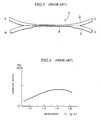
- FIG. 1 one example of a conventional fused-elongated type optical fiber coupler is shown.
- the optical fiber coupler 1 shown in the drawing is formed by aligning a section of each of two component optical fibers 2, mutually thermally fusing the aligned sections thereby forming a fused section, and then elongating or drawing out the heated fused section to form a fused-elongated region 3.
- each component optical fiber 2 is reduced as is the core of the component optical fibers 2.
- a proportionately greater fraction of the energy of the light propagated therein leaks through the cladding which surrounds the core.
- the distance between the cores of adjacent optical fibers 2 is reduced, and due to this fact, the coupling between the propagated modes of the individual fibers becomes extremely great. In this way, the optical signal incident on one fiber 2 becomes split and is thus emitted at ports of both optical fibers 2. In the same way, separate optical signals incident on both component optical fibers 2 become combined.
- the conventional optical fiber coupler 1 With the conventional optical fiber coupler 1 described above, it is known that light incident on one optical fiber becomes proportioned over one or both optical fibers (referred to as coupling ratio) based on the wavelength of the incident light.
- light incident on port A (or port B) of the optical fiber coupler 1 shown in Fig. 1 may be emitted by port C or port D, depending on the wavelength of the incident light.
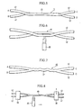
- the graph of Fig. 2 which shows the percentage of light incident on port A of optical fiber coupler 1 that is emitted by port D as a function of the wavelength of the light incident on port A
- the relationship between coupling ratio and wavelength is a sinusoidal function.
- Optical fiber couplers do exist in which the fluctuation of coupling ratio as a function of wavelength is relatively flat. These optical fiber couplers having weak wavelength dependance for coupling ratio are known as wide wavelength range optical fiber couplers, an example of which is shown in Fig. 3.
- the conventional wide wavelength range optical fiber coupler 4 shown in Fig. 3 includes an optical fiber 5, a portion of which has undergone a preliminary elongation, and a conventional optical fiber 2.
- the initially elongated region of optical fiber 5 and a section of optical fiber 2 are aligned side by side and mutually thermally fused to form a fused section.
- the fused section thus formed is then elongated or drawn out to form a fused-elongated region 6.
- Fig. 4 shows for optical fiber coupler 4, the percentage of light incident on port A that is emitted by port D as a function of the wavelength of the light incident on port A.
- Fig. 4 shows, for the conventional wide wavelength range optical fiber coupler 4, while relatively level compared with that of conventional optical fiber coupler 1, the coupling ratio as a function of wavelength does demonstrate a hump and thus, the conventional wide wavelength range optical fiber coupler 4 does not achieve truly flat, wavelength independent characteristics.
- the reason for this is thought to be that for the conventional wide wavelength range optical fiber coupler 4, even after elongation and reduction of the respective fibers' diameters, the central axes of each component optical fiber 2, 5 in the fused-elongated region 6 lie in the same plane.
- the modes which participate in coupling are thought to be limited to the fundamental modes of each core of each component optical fiber 2, 5. Based on light transmission coupling theory, it is believed that for mode coupling between only two modes, that the mode coupling waveform is such that perfectly flat wavelength characteristics cannot be attained.
- each component optical fiber Furthermore, by causing the strength of coupling between the cores of each component optical fiber to vary along the length of the longitudinal axis of each component optical fiber, it is possible to decrease the degree of sinusoidal variation in the wavelength dependance characteristics of each component optical fiber, thereby making it possible to further achieve optical coupling which is wavelength independent and thus considerably constant over a wide range of wavelengths.
- the present invention provides an optical fiber coupler as defined in claim 1, 2 or 3.
- the present invention provides a method of manufacturing an optical fiber coupler as defined in claim 5.
- Fig. 1 is a side view of an example of a conventional optical fiber coupler.
- Fig. 2 is a graph illustrating the wavelength dependency properties of the coupling ratio for the conventional optical fiber coupler shown in Fig. 1.
- Fig. 3 is a side view of an example of a conventional wide bandpass optical fiber coupler.
- Fig. 4 is a graph illustrating the wavelength dependency properties of the coupling ratio for the conventional wide bandpass optical fiber coupler shown in Fig. 3.
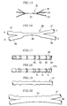
- Fig. 5 is a side view of an optical fiber coupler.
- Fig. 6 is an explanatory side view for one example of a manufacturing method for the optical fiber shown in Fig. 5.
- Fig. 7 is a side view of the optical fiber coupler of a first preferred embodiment of the present invention.
- Fig. 8 is an explanatory side view for one example of a manufacturing method for the optical fiber shown in Fig. 7.
- Fig. 9 is a side view of the optical fiber coupler of a second preferred embodiment of the present invention.
- Figs. 10 through 13 are cross sectional views for the purpose of showing examples of the arrangement of the glass components in the optical fiber coupler shown in Fig. 9.
- Fig. 14 is a graph illustrating the wavelength dependency properties of the coupling ratio for the optical fiber couplers shown in Figs. 5, 7, and 9.
- Fig. 15 is a schematic side view of the optical fiber coupler of a third preferred embodiment of the present invention.
- Fig. 16 is a side view of the optical fiber coupler of a fourth preferred embodiment of the present invention.
- Fig. 17 through 20 are side views for the purpose of explaining one example of the manufacturing steps for the optical fiber shown in Fig. 16.
- Fig. 21 is an explanatory side view for another example of a manufacturing method for the optical fiber shown in Fig. 16.
- Fig. 22 is a side view of the optical fiber coupler of a fifth preferred embodiment of the present invention.
- Fig. 23 is an explanatory side view for one example of a manufacturing method for the optical fiber shown in Fig. 22.
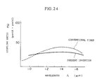
- Fig. 24 is a graph illustrating the wavelength dependency properties of the coupling ratio for the optical fiber couplers shown in Figs. 16 and 22.
- the wide bandpass optical fiber coupler 11 (hereafter referred to as optical fiber coupler) as shown in Fig. 5 consists of a fused-elongated region 13 with a twisting deformation formed from a section of each of two strands of a component single mode optical fiber 12 (hereafter referred to as optical fiber).
- the twisting deformation of the above mentioned fused-elongated region 13 is preferably formed by first imposing a twisting on a section of each component optical fiber 12 prior to forming the fused-elongated region 13, then mutually thermally fusing the twisted sections, and finally drawing out the twisted, thermally fused section.
- the "SZ" twist shown in Fig. 6 has been found to be effective. With this kind of SZ twist, even though a twist is present, each component optical fiber 12 joins and leaves the fused-elongated region 13 on the same side, thus providing more convenient application. Further, with this kind of twisted fused-elongated region 13, very low optical losses and a coupling ratio which is relatively wavelength independent can be easily achieved.
- each of two component optical fibers 12 are aligned side by side, after which the SZ twist shown in the drawing is imparted on the aligned portion of the component optical fibers 12, thereby forming a twisted region 14. While each end of the twisted region 14 is held in a clamp (not shown in the drawing), the twisted region 14 is fused using a hydrogen-oxygen burner 15, after which the above mentioned clamps are moved in opposite directions, thereby stretching and elongating the fused region and forming the fused-elongated region 13. In this way, the optical fiber coupler 11 shown in Fig. 5 can be fabricated.
- optical fiber coupler 11 With this kind of optical fiber coupler 11, by imparting a twisting deformation in the fused-elongated region 13, in addition to the fundamental modes of each component optical fiber 12, additional modes are caused to be formed. Through the participation of these additional modes with the coupling of the fundamental modes, the mode coupling state becomes a multiple mode coupling state, whereby the strength of coupling at predetermined wavelengths can be controlled, and by which means it is possible to create an optical fiber coupler 11 of which the coupling ratio is largely wavelength independent and hence constant over a wide range of wavelengths.
- Such a coupler can be made by using two quartz single mode optical fibers having a core diameter of 9.5 ⁇ m, an external cladding diameter of 125 ⁇ m, a core-cladding refractive index difference of 0.33 %, and a primary coating layer of 250 ⁇ m outer diameter, the primary coating layer was removed from each fiber over a length of 40 mm, thereby exposing the cladding. Next, the exposed sections from the two optical fibers were aligned side by side so that the exposed portions were in contact. An SZ twist was then imposed one time over the section of contacting exposed cores, with both ends of the exposed sections being fixed in a respective clamp.
- the exposed sections between the two clamps were heated with a hydrogen-oxygen burner, whereby a central section of the exposed cores of 20 mm length was mutually fused, while at the same time, the clamps were drawn apart, thereby forming a fused-elongated region having a length of 15 mm and an external diameter of 70 ⁇ m which is the same as the optical fiber coupler 11 shown in Fig. 5.
- the wavelength dependency characteristics of the coupling ratio (the coupling ratio from port A to port C) were measured. From those results it could be seen, as is shown in Fig. 14, that the optical fiber coupler 11 produced by the above described method demonstrated a variation in the strength of the coupling ratio with wavelength that was barely detectable, and thus possessed exceedingly flat wavelength dependency characteristics.
- the optical fiber coupler 16 of the present embodiment as shown in Fig. 7 consists of a fused-elongated region 17 with a wave shaped deformation along its length, formed from a section of each of two component single mode optical fibers 12.
- the extent of the above mentioned wave shaped deformation is not particularly limited, however, ordinarily, an amplitude for the waves of on the order of 5 - 50 % of the external diameter of the fused-elongated region 17 and a frequency such that 2 - 10 cycles occur over the length of the fused-elongated region is preferable. Further, while a wave shaped deformation having a regular cyclic variation is acceptable, it is generally preferable for the amplitude and length of the cycles to vary randomly. Also, with the optical fiber coupler 16 of the present preferred embodiment, it is acceptable to impose a twist of the same configuration as that of the optical fiber coupler 11 of the first preferred embodiment as shown in Fig. 5.
- a portion of each of two component optical fibers 12 are aligned side by side, after which either end of the section to be fused is fixed in a respective clamp 18.
- the region between the two clamps 18 is heated and thereby fused using a hydrogen-oxygen burner 15, after which the clamps are moved apart along the longitudinal axis of the component optical fibers 12, thereby stretching and elongating the fused region and forming an elongated region 19.
- the elongated region 19 thereby formed is then heated at one end by the hydrogen-oxygen burner 15, and as the hydrogen-oxygen burner 15 is gradually moved towards the opposite end, the opposite end is caused shake up and down.
- optical fiber coupler 16 With this kind of optical fiber coupler 16, by imparting a wave shaped deformation along the length of the fused-elongated region 17, in addition to the fundamental modes of each component optical fiber 12, additional modes are caused to be formed. Through the participation of these additional modes with the coupling of the fundamental modes, the mode coupling state becomes a multiple mode coupling state, whereby the strength of coupling at predetermined wavelengths can be controlled, and by which means it is possible to create an optical fiber coupler 16 of which the coupling ratio is largely wavelength independent and hence constant over a wide range of wavelengths.
- the exposed sections of the two optical fibers were aligned side by side with either end of the exposed sections being fixed in a respective clamp.
- the exposed sections between the two clamps were heated with a hydrogen-oxygen burner and mutually fused, while at the same time, the clamps were drawn apart, thereby forming a fused-elongated region.
- one end of the fused-elongated region formed as described above was heated with the hydrogen-oxygen burner, and as the burner was gradually moved toward the opposite end of the fused-elongated region, the clamp holding the opposite end of the fused-elongated region was caused to shake up and down.
- a fused-elongated region having a length of 15 mm and an external diameter of 70 ⁇ m and in which four cycles of a wave shaped deformity were created having an amplitude of approximately 30 ⁇ m.
- the optical fiber coupler thereby formed is the same as the optical fiber coupler 16 shown in Fig. 7.
- the wavelength dependency characteristics of the optical fiber coupler thus obtained demonstrated almost no discernable difference when compared with those of the optical fiber coupler of Figs 5 & 6.
- the wavelength dependency characteristics of the optical fiber coupler of the present experimental example are exceedingly flat.
- the optical fiber coupler 20 of the present embodiment as shown in Fig. 9 consists of a fused-elongated region 21 formed by thermally fusing and then drawing out a section of each of two component optical fibers 12, while at the same time, fusing a section of glass material 22 in the fused-elongated region having the same index of refraction as the cladding of the component optical fibers 12.
- the position at the fused-elongated region 21 where the above mentioned section of glass material 22 is fused is not particularly limited, however, configurations for example as are shown in Figs. 10 through 13 are desirable.
- the section of glass material 22 is positioned parallel to the two cores 23 of the component optical fibers 12 in the fused-elongated region 21 and fused to the outer circumference of the cladding 24 of one of the component optical fibers 12.
- the section of glass material 22 is positioned parallel to the two cores 23 of the component optical fibers 12, and then after the section of glass material 22 is fused to the outer circumference of the cladding 24 of one of the component optical fibers 12, the fused portion is elongated to form the fused-elongated region 21.
- the section of glass material 22 is fused to the outer circumference of the cladding 24 of one of the component optical fibers 12 in the fused-elongated region 21 in proximity to the fused portion of the two component optical fibers 12.
- the section of glass material 22 is fused to the outer circumference of the fused portion of the two component optical fibers 12, after which the fused portion is elongated to form the fused-elongated region 21.
- the shape of the above mentioned glass material 22 is not limited to a rod shape, and glass material 22 in a particulate state is also acceptable.
- the index of refraction be equal to that of the cladding 24 of the component optical fibers 12.
- the optical fiber coupler 20 of the present embodiment by employing a glass material 22 having the same index of refraction as that of the material for the cladding 24 of the component optical fibers 12, in addition to the fundamental modes of each component optical fiber 12, additional modes are caused to be formed.
- the mode coupling state becomes a multiple mode coupling state, whereby the strength of coupling at predetermined wavelengths can be controlled, and by which means it is possible to create an optical fiber coupler 20 of which the coupling ratio is largely wavelength independent and hence constant over a wide range of wavelengths.
- the optical fiber coupler 20 of the present preferred embodiment incorporates a fused-elongated region 21 in which the component optical fibers 12 are fused and drawn out and to which glass material 22 is further fused.
- the wavelength dependency characteristics of the optical fiber coupler thus obtained demonstrated almost no discernable difference when compared with those of the optical fiber coupler of the first preferred embodiment.
- the wavelength dependency characteristics of the optical fiber coupler of the present experimental example are exceedingly flat.
- the optical fiber coupler 31 of the present embodiment as shown in Fig. 15 consists of a fused-elongated region 35 formed by thermally fusing and then drawing out a section of each of three component optical fibers 32, 33, and 34.
- the three component optical fibers 32, 33, and 34 are such that, among each of the fibers parameters (fiber diameter, core diameter, core-cladding refractive index difference, etc.), at least one parameter varies cyclically with a relatively short cycle length over the length of the fused-elongated region 35.
- the strength of the coupling ratio between the cores of the component optical fibers 32, 33, and 34 varies over the length of the fused-elongated region 35.
- the light signal incident on one of the three component optical fibers 32, 33, and 34 is caused to branch, or alternately, light signals incident on all three component optical fibers 32, 33, and 34 are caused to couple.
- a plurality of component optical fibers 32, 33, and 34 of which one or more parameters vary along the longitudinal length are aligned side by side, after which a portion of the aligned fibers is thermally fused, and then drawn out to form the fused-elongated region 35.
- the optical fiber coupler 36 of the present embodiment as shown in Fig. 16 consists of a fused-elongated region 39 formed by mutually thermally fusing and then drawing out a section of a variable diameter optical fiber 37 of which the external diameter varies along the length of the fiber, and a fixed diameter optical fiber 38 having a constant external diameter.
- variable diameter optical fiber 37 is a fiber of which, along a portion of its length of plurality of reduced diameter sections have been formed.
- the extent of the diameter reduction in the above mentioned reduced diameter sections is suitably determined based on the optical fiber diameter, core diameter, and other factors.
- a core diameter of on the order of 10 ⁇ m, a constriction 50 ⁇ m or less, or more preferably, on the order of 30 - 40 ⁇ m is suitable.
- the reduced diameter sections should have an external diameter of at least 75 ⁇ m, or more preferably, on the order of 85 - 95 ⁇ m.
- Over the length that the variable diameter optical fiber 37 is fused with the fixed diameter optical fiber 38 that is, over 10 to 20 mm, on the of order of three to six occurrences of the reduced diameter sections are preferable.
- variable diameter optical fiber 37 is such that among the fibers parameters (fiber diameter, core diameter, core-cladding refractive index difference, etc.), the fiber diameter is caused to vary cyclically with a relatively short cycle length along the longitudinal axis of the fiber, when a section of such a variable diameter optical fiber 37 is fused with a fixed diameter optical fiber 38, after which the fused section is drawn out to form the fused-elongated region 39, it is possible to decrease the degree of sinusoidal variation in the wavelength dependance characteristics of each component optical fiber, thereby making it possible to fabricate an optical fiber coupler 36 having a more constant coupling ratio with respect to wavelength than a conventional wide wavelength range optical fiber coupler.
- the fused-elongated region 39 of the optical fiber coupler 36 of the present embodiment is formed from a variable diameter optical fiber 37 and a fixed diameter optical fiber 38, it is also acceptable to the form the optical fiber coupler 36 by mutually fusing and drawing out a portion of each of two variable diameter optical fibers 37.
- Figs. 17 through 20 illustrate the various stages of a suitable process.
- a plurality of encircling narrow bands of a resist layer 40 are applied, preferably so that over the length that the variable diameter optical fiber 37 is fused with the fixed diameter optical fiber 38, that is, over 10 to 20 mm, on the of order of three to six of the bands of resist layer 40 are present.
- the width of the bands of resist layer 40 are not particularly limited, however, a width of on the order of 10 to 30 % of the external diameter of the optical fiber is generally preferable.
- a resin composition that is resistant to glass etchant is desirable.
- the optical fiber 38 is dipped in etchant, whereby the bands not covered by the bands of resist layer 40 are etched, thereby forming reduced diameter sections 41.
- etchant a glass-corrosive etchant that is capable of etching the quartz cladding of the optical fiber 38 is suitable, and in particular, an acid type etchant can be suitably applied.
- the optical fiber is removed from the etchant and rinsed with water, after which the bands of resist layer 40 are removed with a suitable solvent.
- variable diameter optical fiber 37a is formed having a plurality of reduced diameter sections 41 along its length, as is shown in Fig. 18.
- the variable diameter optical fiber 37a formed by the above described etching process can be used immediately, however, it is preferable to subject the etched variable diameter optical fiber 37a shown in Fig. 18 to fire polishing by heating the outer surface of the optical fiber 37a with a hydrogen-oxygen flame, whereby the transitions between the reduced diameter sections 41 and the non-etched sections is caused to be less sharp, as is shown in Fig. 19.
- variable diameter optical fiber 37 shown in Fig. 19 and a fixed diameter optical fiber 38 are aligned side by side, after which the aligned fibers are mutually thermally fused over a portion of their length, thereby forming a fused section 42 as shown in Fig. 20, which is then drawn out to form the fused-elongated region 39.
- the optical fiber coupler 36 shown in Fig. 16 is fabricated.
- the manufacturing method according to the above described example because the provided aqueous etching process can be carried out in one step, thereby forming a plurality of the reduced diameter sections 41, the manufacture of the variable diameter optical fiber 37 can be carried out easily, efficiently, and at the same time, reduced diameter sections 41 are uniformly formed.
- FIG. 21 another example of a manufacturing method for the optical fiber coupler 36 shown in Fig. 16 is illustrated.
- variable diameter optical fiber 37 is formed by dry etching
- a hydrogen-oxygen burner 43 is used for which the hydrogen-oxygen gas mixture also includes glass-corrosive fluorine gas. Applying the burner at fixed intervals along the surface of a fixed diameter optical fiber 38 and thereby etching the outer surface at the point where the burner is applied, a plurality of reduced diameter sections 41 are formed at fixed intervals, thereby forming the variable diameter optical fiber 37.
- the manufacturing process is generally easier and more efficient than when compared with the aqueous etching described previously.
- the optical fiber coupler 36 shown in Fig. 16 was manufactured.
- resist layer was applied over a portions of the surface of a strand of the above described optical fiber material, leaving the surface of the optical fiber exposed at the portions to be etched.
- the fiber was immersed in hydrofluoric acid for approximately ten hours thereby carrying out etching, after which the fiber was rinsed with water.
- the optical fiber was then washed in an organic solvent in order to remove the UV setting resin previously applied.
- an optical fiber was formed having over a portion of its length four etched sections (reduced diameter sections) of a depth of approximately 40 ⁇ m and a width of approximately 4 mm. The interval between adjacent etched sections was approximately 800 ⁇ m.
- the etched optical fiber was fire polished in a hydrogen-oxygen flame, whereby a variable diameter optical fiber was formed.
- the variable diameter optical fiber thereby formed and a fixed diameter optical fiber were then aligned side by side, after which the aligned fibers were fixed in a pair of clamps, one at either end of the etched region formed as described above.
- the section of the two optical fibers between the two clamps was then heated with an hydrogen-oxygen flame, whereby a fused section of approximately 20 mm in length was formed.
- the clamps were then drawn apart along the longitudinal axis of the optical fibers, by which means a fused-elongated region approximately 15 mm long was formed which was identical with the optical fiber coupler 36 shown in Fig. 16.
- the wavelength dependency characteristics of the optical fiber coupler thus obtained were measured, the results of which are shown in Fig. 24.
- the coupling ratio of the optical fiber coupler 36 is relatively flat with respect to the wavelength of the incident light.
- the optical fiber coupler 44 of the present embodiment as shown in Fig. 15 consists of a fused-elongated region 46 formed by thermally fusing a section of each of two component optical fibers 38, 45 and then drawing out the fused section.
- the component optical fiber 38 is a fixed diameter optical fiber 38 as was described for the previous example.
- the component optical fiber 45 is a variable propagation constant optical fiber 45 of which the diameter of the core and the external diameter of the cladding varies over the length of the fiber, whereby the propagation constant of the optical fiber 45 is caused to vary over its length.
- the above mentioned variable propagation constant optical fiber 45 is manufactured by causing a plurality of swellings and constrictions to be formed in an ordinary optical fiber 38, whereby the diameter of the core and the external diameter of the cladding is caused to vary over the length of the fiber, by which means the propagation constant of the optical fiber 45 is caused to vary along its length.
- the above mentioned plurality of swellings and constrictions are formed by heating the ordinary optical fiber 38 and applying pressure or tension at various points, thereby creating portions having increased or reduced diameters over a section of the optical fiber 38. It is preferable that the above mentioned swellings and constrictions are formed so that there are approximately three to six occurrences over the length of the optical fiber 45 that is to be fused, that is, over 10 to 20 mm.
- variable propagation constant optical fiber 45 is such that the outer fiber diameter and core diameter are caused to vary cyclically with a relatively short cycle length along the longitudinal axis of the fiber, and hence the propagation constant is caused vary along the longitudinal axis of the fiber
- a section of such a variable propagation constant optical fiber 45 is fused with a fixed propagation constant optical fiber 38, after which the fused section is drawn out to form the fused-elongated region 46, it is possible to decrease the degree of sinusoidal variation in the wavelength dependance characteristics of each component optical fiber, thereby making it possible to fabricate an optical fiber coupler 44 having a more constant coupling ratio with respect to wavelength than a conventional wide wavelength range optical fiber coupler.
- the optical fiber coupler 44 of the present embodiment was formed by mutually fusing a section from each of a variable propagation constant optical fiber 45 and a fixed propagation constant optical fiber 38.
- FIG. 23 an example of one fabrication method of the optical fiber coupler 44 of the present embodiment is shown.
- a section of a fixed propagation constant optical fiber 38 is fixed at either end by a pair of clamps 47.
- the section of optical fiber 38 between the two clamps 47 is locally heated with a hydrogen-oxygen burner 48, after which the clamps 47 are either moved apart or together, thereby applying respectively tension or pressure to the section of optical fiber 38 between the two clamps 47, and hence at the locally heated portion.
- a plurality of swellings 49 and constrictions 50 are formed in a section of the optical fiber 38, thus forming the variable propagation constant optical fiber 45.
- variable propagation constant optical fiber 45 thus formed and a fixed propagation constant optical fiber 38 are aligned side by side, and a section from each are mutually thermally fused, and then drawn out, thereby forming the fused-elongated region 46.
- the optical fiber coupler 44 shown in Fig. 22 is thus manufactured.
- variable propagation constant optical fiber thus formed and a fixed propagation constant optical fiber were aligned side by side, and a section from each are mutually thermally fused, and then drawn out by the same method of experimental example 4, thereby forming a fused-elongated region, by which means the optical fiber coupler 44 shown in Fig. 22 was manufactured.
- optical fiber coupler of the present invention includes all forms encompassed by the appended claims.
Landscapes
- Physics & Mathematics (AREA)
- General Physics & Mathematics (AREA)
- Optics & Photonics (AREA)
- Engineering & Computer Science (AREA)
- Plasma & Fusion (AREA)
- Optical Couplings Of Light Guides (AREA)
- Optical Integrated Circuits (AREA)
Claims (8)
- Faseroptischer Koppler, der durch Verschweißen aneinandergrenzender seitlicher Teile von mindestens zwei optischen Teilfasern, die sich nebeneinander erstrecken, und anschließendes Dehnen des verschweißten Abschnitts zur Bildung eines verschweißten und gedehnten Bereichs gebildet wird;
wobei der faseroptische Koppler dadurch gekennzeichnet ist, daß mindestens einer der folgenden Faserparameter - Außendurchmesser der Faser, Kerndurchmesser und Brechungsindex-Differenz zwischen Kern und Mantel - von mindestens einer der mindestens beiden optischen Teilfasern auf der Länge des verschweißten und gedehnten Bereichs wiederholt abnimmt und zunimmt, so daß das Modenkopplungsverhältnis zwischen den Kernen der mindestens zwei optischen Teilfasern gleichfalls an verschiedenen Punkten entlang der Längsachse des verschweißten und gedehnten Bereichs wiederholt variiert, wodurch sich über einen breiten Wellenlängenbereich eine im wesentlichen wellenlängenunabhängige Kopplungsstärke ergibt. - Faseroptischer Koppler, der durch Verschweißen aneinandergrenzender seitlicher Teile von mindestens zwei optischen Teilfasern, die sich nebeneinander erstrecken, und anschließendes Dehnen des verschweißten Abschnitts zur Bildung eines verschweißten und gedehnten Bereichs gebildet wird; wobei der optische Koppler dadurch gekennzeichnet ist, daß der verschweißte und gedehnte Bereich eine serpentinenförmige Störung aufweist, die in eine oder mehrere der mindestens zwei optischen Teilfasern (12) in dem verschweißten und gedehnten Bereich (17) eingebaut ist.
- Faseroptischer Koppler, der durch Verschweißen aneinandergrenzender seitlicher Teile von mindestens zwei optischen Teilfasern, die sich nebeneinander erstrecken, und anschließendes Dehnen des verschweißten Abschnitts zur Bildung eines verschweißten und gedehnten Abschnitts gebildet wird; wobei der optische Koppler dadurch gekennzeichnet ist, daß der verschweißte und gedehnte Bereich eine Störung aufweist, die durch einen zusätzlichen gedehnten Abschnitt aus Glasmaterial (22) entsteht, das in mindestens eine der optischen Teilfasern (12) oder in den verschweißten und gedehnten Bereich (21) eingeschmolzen worden ist, wobei das Glasmaterial (22) einen Brechungsindex aufweist, der nicht größer ist als der Brechungsindex eines Mantels der einen oder mehreren optischen Teilfasern (12).
- Faseroptischer Koppler nach Anspruch 1, wobei die wiederholte Zunahme und Abnahme des Faserparameters zyklisch erfolgt, mit einer relativ kurzen Periode im Vergleich zur Länge des gedehnten Bereichs.
- Verfahren zur Herstellung eines faseroptischen Kopplers, wobei Abschnitte von jeder von mindestens zwei optischen Teil fasern nebeneinander ausgerichtet und thermisch miteinander verschweißt werden, wodurch ein verschweißter Abschnitt entsteht, und wobei der verschweißte Bereich dann gedehnt wird, um einen verschweißten und gedehnten Bereich zu bilden;
wobei das Verfahren zur Herstellung des faseroptischen Kopplers dadurch gekennzeichnet ist, daß mindestens eine der mindestens zwei optischen Teilfasern so beschaffen ist, daß einer oder mehrere der folgenden Parameter - Außendurchmesser der Faser, Kerndurchmesser und Brechungsindex-Differenzen zwischen Kern und Mantel - der optischen Faser auf der Länge des verschweißten und gedehnten Bereichs wiederholt abnimmt und zunimmt, wodurch sich über einen breiten Wellenlängenbereich eine im wesentlichen wellenlängenunabhängige Kopplungsstärke ergibt. - Verfahren nach Anspruch 5, wobei mindestens eine von mindestens zwei optischen Teilfasern (37 und 38) eine optische Faser (37) mit variablem Durchmesser ist, deren Durchmesser entlang einer Längsachse der optischen Faser (37) mit variablem Durchmesser wiederholt variiert, wobei die optische Faser (37) mit variablem Durchmesser durch ein Ätzverfahren gebildet wird, das ein Naßätzverfahren ist, bei dem Bänder aus einer Resistschicht (49) in festgelegten Abständen zumindest über einen Abschnitt einer optischen Faser (38) auf den äußeren Umfang der optischen Faser (38) aufgebracht werden, wodurch auf dem Abschnitt der optischen Faser (38) periphere, abwechselnd blanke faseroptische Bänder (38) und mit der Resistschicht (40) bedeckte faseroptische Bänder entstehen, mit anschließendem Eintauchen des Abschnitts der optischen Faser in ein Ätzmittel, wodurch die blanken faseroptischen Bänder (38) geätzt werden, und anschließendem Entfernen der Resistschicht (40), wodurch eine optische Faser (37) mit variablem Außendurchmesser erzeugt wird.
- Verfahren nach Anspruch 5, wobei mindestens eine der mindestens zwei optischen Teilfasern eine optische Faser (37) mit variablem Durchmesser ist, deren Durchmesser entlang einer Längsachse der optischen Faser mit variablem Durchmesser wiederholt variiert, wobei die optische Faser mit variablem Durchmesser durch ein Ätzverfahren hergestellt wird, wobei das Atzverfahren ein Trockenätzverfahren ist, bei dem eine Flamme, die ein Gas mit glaskorrosiven Eigenschaften enthält, auf mindestens eine Stelle entlang mindestens einem Abschnitt einer optischen Faser (38) angewandt wird, wodurch ein Trockenätzen der optischen Faser (38) an der mindestens einen Stelle entlang mindestens einem Abschnitt der optischen Faser (38) veranlaßt wird, wodurch die optische Faser (37) mit variablem Außendurchmesser hergestellt wird.
- Verfahren nach Anspruch 5, wobei mindestens eine von mindestens zwei optischen Teilfasern (38 und 45) eine optische Faser mit variablem Ausbreitungskoeffizienten ist, was darauf zurückzuführen ist, daß die Faser (45) anfänglich mehrere Ausbauchungen und Einschnürungen aufweist, die durch Erhitzen und Anwenden von Druck oder Zug an verschiedenen Punkten entlang einer Längsachse der optischen Faser (38) ausgebildet wurden.
Priority Applications (1)
| Application Number | Priority Date | Filing Date | Title |
|---|---|---|---|
| EP98100271A EP0840148B1 (de) | 1989-06-22 | 1990-06-22 | Optischer Faserkoppler und Verfahren zu seiner Herstellung |
Applications Claiming Priority (4)
| Application Number | Priority Date | Filing Date | Title |
|---|---|---|---|
| JP159969/89 | 1989-06-22 | ||
| JP15996989A JPH0324506A (ja) | 1989-06-22 | 1989-06-22 | 広波長域形光ファイバカプラ |
| JP191908/89 | 1989-07-25 | ||
| JP19190889A JPH0355505A (ja) | 1989-07-25 | 1989-07-25 | 光ファイバカプラおよびその製造方法 |
Related Child Applications (1)
| Application Number | Title | Priority Date | Filing Date |
|---|---|---|---|
| EP98100271A Division EP0840148B1 (de) | 1989-06-22 | 1990-06-22 | Optischer Faserkoppler und Verfahren zu seiner Herstellung |
Publications (3)
| Publication Number | Publication Date |
|---|---|
| EP0404587A2 EP0404587A2 (de) | 1990-12-27 |
| EP0404587A3 EP0404587A3 (de) | 1992-01-08 |
| EP0404587B1 true EP0404587B1 (de) | 1998-08-19 |
Family
ID=26486606
Family Applications (2)
| Application Number | Title | Priority Date | Filing Date |
|---|---|---|---|
| EP90306839A Expired - Lifetime EP0404587B1 (de) | 1989-06-22 | 1990-06-22 | Faseroptischer Koppler und eine Methode seiner Herstellung |
| EP98100271A Expired - Lifetime EP0840148B1 (de) | 1989-06-22 | 1990-06-22 | Optischer Faserkoppler und Verfahren zu seiner Herstellung |
Family Applications After (1)
| Application Number | Title | Priority Date | Filing Date |
|---|---|---|---|
| EP98100271A Expired - Lifetime EP0840148B1 (de) | 1989-06-22 | 1990-06-22 | Optischer Faserkoppler und Verfahren zu seiner Herstellung |
Country Status (3)
| Country | Link |
|---|---|
| US (1) | US5058979A (de) |
| EP (2) | EP0404587B1 (de) |
| DE (2) | DE69032573T2 (de) |
Cited By (1)
| Publication number | Priority date | Publication date | Assignee | Title |
|---|---|---|---|---|
| WO2005057260A1 (ja) * | 2003-12-09 | 2005-06-23 | Osaki Electric Co., Ltd. | 光ファイバカプラおよびその製造方法並びにその製造装置 |
Families Citing this family (21)
| Publication number | Priority date | Publication date | Assignee | Title |
|---|---|---|---|---|
| US5146519A (en) * | 1990-08-28 | 1992-09-08 | Corning Incorporated | Rotary variable optical tap |
| DE4109982A1 (de) * | 1991-03-27 | 1992-10-01 | Standard Elektrik Lorenz Ag | Verfahren zur herstellung eines optischen verschmelzkopplers |
| DE69228667T2 (de) * | 1991-12-24 | 1999-09-30 | Whitaker Corp | Optisches Kopplungselement |
| US5319733A (en) * | 1992-01-02 | 1994-06-07 | Adc Telecommunications, Inc. | Variable fiber optical attenuator |
| EP0694173A1 (de) * | 1992-01-02 | 1996-01-31 | Adc Telecommunications, Inc. | Überlappendes geschweistes dämpfungsglied |
| US6148129A (en) * | 1993-01-15 | 2000-11-14 | E-Tek Dynamics, Inc. | Broad bandwidth, single mode fiber optic coupler and method of manufacture |
| GB2280968B (en) * | 1993-08-12 | 1996-07-31 | Northern Telecom Ltd | Chirped optical fibre filter |
| CA2123757C (en) * | 1994-05-17 | 2002-06-25 | Francois Gonthier | Method for making optical waveguide couplers with low wavelength sensitivity and couplers thereby produced |
| US5411566A (en) * | 1994-06-08 | 1995-05-02 | At&T Corp. | Optical fiber spatial mode converter using periodic core deformation |
| FR2725529B1 (fr) * | 1994-10-11 | 1996-11-22 | Alcatel Nv | Coupleur optique selectif en longueur d'onde |
| FR2725528B1 (fr) * | 1994-10-11 | 1996-11-22 | Alcatel Nv | Ligne a retard optique selectif en longueur d'onde |
| US5652819A (en) * | 1995-08-09 | 1997-07-29 | The United States Of America As Represented By The Secretary Of The Navy | Method for tuning fiber optic couplers and multiplexers |
| US5694512A (en) * | 1996-07-09 | 1997-12-02 | Framatome Connectors Canada Inc. | Compact tunable wavelength independent all-fiber optical attenuator and method of making same |
| CA2266621A1 (en) * | 1996-09-24 | 1998-04-02 | Cary Bloom | Apparatus and method for controlled heating and deforming of an optic fiber |
| US6363190B1 (en) * | 2000-02-11 | 2002-03-26 | New Focus, Inc. | Polarization insensitive fused fiber coupler method and apparatus |
| US20070066076A1 (en) * | 2005-09-19 | 2007-03-22 | Bailey Joel B | Substrate processing method and apparatus using a combustion flame |
| US6928841B2 (en) * | 2002-05-10 | 2005-08-16 | Furukawa Electric North America Inc | Optical fiber preform manufacture using improved VAD |
| US7896218B2 (en) * | 2007-06-28 | 2011-03-01 | Western Digital Technologies, Inc. | Apparatus and method for conductive metal ball bonding with electrostatic discharge detection |
| AU2013399606B2 (en) | 2013-09-09 | 2016-09-22 | Halliburton Energy Services, Inc. | Activation of set-delayed cement compositions by retarder exchange |
| CN103792620B (zh) * | 2014-02-21 | 2016-01-06 | 嘉隆科技(深圳)有限公司 | 一种抗弯曲光纤耦合器及其制造方法 |
| CN109031531A (zh) * | 2018-08-06 | 2018-12-18 | 上海大学 | 一种具有波分复用功能的模式耦合器及其制备方法 |
Family Cites Families (11)
| Publication number | Priority date | Publication date | Assignee | Title |
|---|---|---|---|---|
| CA1123642A (en) * | 1979-07-04 | 1982-05-18 | Alexander W. Lightstone | Multimode optical fiber coupler |
| US4586784A (en) * | 1983-06-10 | 1986-05-06 | Canadian Patents & Dev. Limited | Modal-insensitive biconical taper couplers |
| AU569803B2 (en) * | 1984-09-06 | 1988-02-18 | Hitachi Limited | Optical fibre star coupler |
| GB8519183D0 (en) * | 1985-07-30 | 1985-09-04 | British Telecomm | Optical fused couplers |
| EP0219096A3 (de) * | 1985-10-16 | 1989-08-16 | Hitachi, Ltd. | Faseroptischer Sternkoppler und seine Herstellungsmethode |
| US4746185A (en) * | 1986-06-23 | 1988-05-24 | Shahidi Hamedani Ferrydon | Optical fibre couplers |
| JPH0827418B2 (ja) * | 1987-02-18 | 1996-03-21 | 住友電気工業株式会社 | 分岐用光フアイバケ−ブル |
| US4869570A (en) * | 1987-02-21 | 1989-09-26 | Nippon Telegraph And Telephone Corporation | Fiber coupler and method and apparatus for manufacturing the same |
| US4763272A (en) * | 1987-03-29 | 1988-08-09 | The United States Of America As Represented By The Secretary Of The Navy | Automated and computer controlled precision method of fused elongated optical fiber coupler fabrication |
| JPS63244010A (ja) * | 1987-03-31 | 1988-10-11 | Sumitomo Electric Ind Ltd | 余長付光フアイバケ−ブルの製造方法 |
| GB2207254B (en) * | 1987-07-11 | 1991-03-13 | Stc Plc | Glass clad optical fibre directional couplers. |
-
1990
- 1990-06-21 US US03/242,469 patent/US5058979A/en not_active Expired - Lifetime
- 1990-06-22 EP EP90306839A patent/EP0404587B1/de not_active Expired - Lifetime
- 1990-06-22 DE DE69032573T patent/DE69032573T2/de not_active Expired - Fee Related
- 1990-06-22 DE DE69033788T patent/DE69033788T2/de not_active Expired - Fee Related
- 1990-06-22 EP EP98100271A patent/EP0840148B1/de not_active Expired - Lifetime
Cited By (1)
| Publication number | Priority date | Publication date | Assignee | Title |
|---|---|---|---|---|
| WO2005057260A1 (ja) * | 2003-12-09 | 2005-06-23 | Osaki Electric Co., Ltd. | 光ファイバカプラおよびその製造方法並びにその製造装置 |
Also Published As
| Publication number | Publication date |
|---|---|
| EP0404587A2 (de) | 1990-12-27 |
| EP0404587A3 (de) | 1992-01-08 |
| DE69033788T2 (de) | 2002-05-02 |
| EP0840148A2 (de) | 1998-05-06 |
| DE69032573D1 (de) | 1998-09-24 |
| EP0840148B1 (de) | 2001-08-29 |
| EP0840148A3 (de) | 1998-11-25 |
| US5058979A (en) | 1991-10-22 |
| DE69033788D1 (de) | 2001-10-04 |
| DE69032573T2 (de) | 1999-04-08 |
Similar Documents
| Publication | Publication Date | Title |
|---|---|---|
| EP0404587B1 (de) | Faseroptischer Koppler und eine Methode seiner Herstellung | |
| CA1277126C (en) | Method of making a single-mode evanescent-wave coupler having reduced wavelength dependence | |
| CA1254783A (en) | Optical star coupler and method for manufacturing the same | |
| EP0266040A2 (de) | Optischer Koppler für Multimode-Fasern und Herstellungsverfahren | |
| US4799949A (en) | Method of making low loss fiber optic coupler | |
| US4902324A (en) | Method of reproducibly making fiber optic coupler | |
| US4330170A (en) | Low-loss star couplers for optical fiber systems | |
| JPH08304662A (ja) | 光ファイバ結合器 | |
| CA1321072C (en) | Method of manufacturing optical branching and coupling device | |
| JPS61245115A (ja) | 受動繊維光学素子 | |
| US5009692A (en) | Method of making fiber optic coupler | |
| KR100358418B1 (ko) | 용융형 모드분할 방향성 결합기의 제조방법 | |
| EP0610973B1 (de) | Faseroptischer Koppler | |
| EP0148863B1 (de) | Polarisationsunempfindlicher schmelzkoppler mit evanescierender welle und minimaler umweltempfindlichkeit | |
| US5129020A (en) | Wavelength selective optical fiber coupler | |
| EP0576299A2 (de) | Optische Koppler | |
| WO1988009943A1 (en) | Asymmetric fibre optic couplers and their fabrication | |
| US5644666A (en) | Broadband optical fiber coupler and method of making | |
| US5883992A (en) | Method for making optical waveguide couplers with low wavelength sensitivity and couplers thereby produced | |
| EP0209998A2 (de) | Herstellung von optischen Faser-Verbindungen und Verfahren von Abstimmung mittels Diffusion | |
| Lesa et al. | The effect of immersion time on singlemode-tapered multimode-singlemode (STMS) fabrication using a chemical etching method | |
| JP3101958B2 (ja) | 広帯域カップラおよびその製造方法 | |
| JPH0355505A (ja) | 光ファイバカプラおよびその製造方法 | |
| JPH04315108A (ja) | 偏波保持光ファイバカプラの製造方法 | |
| JPH02110409A (ja) | 光ファイバカプラ |
Legal Events
| Date | Code | Title | Description |
|---|---|---|---|
| PUAI | Public reference made under article 153(3) epc to a published international application that has entered the european phase |
Free format text: ORIGINAL CODE: 0009012 |
|
| AK | Designated contracting states |
Kind code of ref document: A2 Designated state(s): DE FR GB |
|
| 17P | Request for examination filed |
Effective date: 19901126 |
|
| PUAL | Search report despatched |
Free format text: ORIGINAL CODE: 0009013 |
|
| AK | Designated contracting states |
Kind code of ref document: A3 Designated state(s): DE FR GB |
|
| 17Q | First examination report despatched |
Effective date: 19931214 |
|
| GRAG | Despatch of communication of intention to grant |
Free format text: ORIGINAL CODE: EPIDOS AGRA |
|
| GRAG | Despatch of communication of intention to grant |
Free format text: ORIGINAL CODE: EPIDOS AGRA |
|
| GRAG | Despatch of communication of intention to grant |
Free format text: ORIGINAL CODE: EPIDOS AGRA |
|
| GRAH | Despatch of communication of intention to grant a patent |
Free format text: ORIGINAL CODE: EPIDOS IGRA |
|
| GRAH | Despatch of communication of intention to grant a patent |
Free format text: ORIGINAL CODE: EPIDOS IGRA |
|
| GRAA | (expected) grant |
Free format text: ORIGINAL CODE: 0009210 |
|
| AK | Designated contracting states |
Kind code of ref document: B1 Designated state(s): DE FR GB |
|
| REF | Corresponds to: |
Ref document number: 69032573 Country of ref document: DE Date of ref document: 19980924 |
|
| ET | Fr: translation filed | ||
| PLBE | No opposition filed within time limit |
Free format text: ORIGINAL CODE: 0009261 |
|
| STAA | Information on the status of an ep patent application or granted ep patent |
Free format text: STATUS: NO OPPOSITION FILED WITHIN TIME LIMIT |
|
| 26N | No opposition filed | ||
| REG | Reference to a national code |
Ref country code: GB Ref legal event code: IF02 |
|
| PGFP | Annual fee paid to national office [announced via postgrant information from national office to epo] |
Ref country code: FR Payment date: 20020610 Year of fee payment: 13 |
|
| PGFP | Annual fee paid to national office [announced via postgrant information from national office to epo] |
Ref country code: GB Payment date: 20020619 Year of fee payment: 13 |
|
| PGFP | Annual fee paid to national office [announced via postgrant information from national office to epo] |
Ref country code: DE Payment date: 20020626 Year of fee payment: 13 |
|
| PG25 | Lapsed in a contracting state [announced via postgrant information from national office to epo] |
Ref country code: GB Free format text: LAPSE BECAUSE OF NON-PAYMENT OF DUE FEES Effective date: 20030622 |
|
| PG25 | Lapsed in a contracting state [announced via postgrant information from national office to epo] |
Ref country code: DE Free format text: LAPSE BECAUSE OF NON-PAYMENT OF DUE FEES Effective date: 20040101 |
|
| GBPC | Gb: european patent ceased through non-payment of renewal fee |
Effective date: 20030622 |
|
| PG25 | Lapsed in a contracting state [announced via postgrant information from national office to epo] |
Ref country code: FR Free format text: LAPSE BECAUSE OF NON-PAYMENT OF DUE FEES Effective date: 20040227 |
|
| REG | Reference to a national code |
Ref country code: FR Ref legal event code: ST |