EP0404566A2 - Feststellung der Grösse eines Dokuments durch Kalibrierung eines Verschlusses - Google Patents
Feststellung der Grösse eines Dokuments durch Kalibrierung eines Verschlusses Download PDFInfo
- Publication number
- EP0404566A2 EP0404566A2 EP90306789A EP90306789A EP0404566A2 EP 0404566 A2 EP0404566 A2 EP 0404566A2 EP 90306789 A EP90306789 A EP 90306789A EP 90306789 A EP90306789 A EP 90306789A EP 0404566 A2 EP0404566 A2 EP 0404566A2
- Authority
- EP
- European Patent Office
- Prior art keywords
- document
- open position
- shutter
- distance
- platen
- Prior art date
- Legal status (The legal status is an assumption and is not a legal conclusion. Google has not performed a legal analysis and makes no representation as to the accuracy of the status listed.)
- Granted
Links
Images

Classifications
-
- G—PHYSICS
- G03—PHOTOGRAPHY; CINEMATOGRAPHY; ANALOGOUS TECHNIQUES USING WAVES OTHER THAN OPTICAL WAVES; ELECTROGRAPHY; HOLOGRAPHY
- G03G—ELECTROGRAPHY; ELECTROPHOTOGRAPHY; MAGNETOGRAPHY
- G03G15/00—Apparatus for electrographic processes using a charge pattern
- G03G15/60—Apparatus which relate to the handling of originals
- G03G15/605—Holders for originals or exposure platens
-
- G—PHYSICS
- G03—PHOTOGRAPHY; CINEMATOGRAPHY; ANALOGOUS TECHNIQUES USING WAVES OTHER THAN OPTICAL WAVES; ELECTROGRAPHY; HOLOGRAPHY
- G03G—ELECTROGRAPHY; ELECTROPHOTOGRAPHY; MAGNETOGRAPHY
- G03G15/00—Apparatus for electrographic processes using a charge pattern
- G03G15/60—Apparatus which relate to the handling of originals
- G03G15/607—Apparatus which relate to the handling of originals for detecting size, presence or position of original
-
- G—PHYSICS
- G03—PHOTOGRAPHY; CINEMATOGRAPHY; ANALOGOUS TECHNIQUES USING WAVES OTHER THAN OPTICAL WAVES; ELECTROGRAPHY; HOLOGRAPHY
- G03G—ELECTROGRAPHY; ELECTROPHOTOGRAPHY; MAGNETOGRAPHY
- G03G2215/00—Apparatus for electrophotographic processes
- G03G2215/00172—Apparatus for electrophotographic processes relative to the original handling
- G03G2215/00177—Apparatus for electrophotographic processes relative to the original handling for scanning
- G03G2215/00181—Apparatus for electrophotographic processes relative to the original handling for scanning concerning the original's state of motion
- G03G2215/00185—Apparatus for electrophotographic processes relative to the original handling for scanning concerning the original's state of motion original at rest
Definitions
- This invention relates generally to an electrophotographic printing machine, and more particularly concerns an apparatus for detecting the size of an original document being reproduced thereon and calibrating shutters used therein.
- a photoconductive member is charged to a substantially uniform potential so as to sensitize the surface thereof.
- the charged portion of the photoconductive member is exposed to a light image of an original document being reproduced.
- Exposure of the charged photoconductive member selectively dissipates the charge in the irradiated areas to record an electrostatic latent image on the photoconductive member.
- the latent image is developed by bringing a developer material into contact therewith.
- the developer material comprises toner particles adhering triboelectrically to carrier granules.
- the toner particles are attracted from the carrier granules to the latent image forming a toner powder image on the photoconductive member.
- the toner powder image is then transferred from the photoconductive member to a copy sheet.
- the toner particles are heated to permanently affix the powder image to the copy sheet.
- the size of the document is detected and a copy sheet of appropriate size selected corresponding thereto.
- the copying machine selects the appropriate size copy sheet depending upon the size of the original document and the reduction/magnification selected.
- the size of an original document placed on a platen of a printing machine was detected by a combination of light emitting devices and photodetectors.
- the photodetectors are arranged to receive light reflected from the original document and to determine the size of the original document based on the conditions detected by the photodetectors.
- the platen supporting the original document is a substantially planar, transparent member. Portions of the platen extend beyond the side edges of the original document. When the original document is exposed, light rays are transmitted through the platen in those regions not supporting the original document. In order to discharge the photoconductive surface in those regions, the platen cover has a light reflective surface thereon which reflects the light rays transmitted through the platen back onto the charged border regions of the photoconductive surface surrounding the latent image corresponding to the original document. Shutters are used to block the regions of the platen extending beyond the sides of the original document. The shutters move from a fully open position to a position adjacent the sides of the original document.
- the shutters prevent light rays from passing through the platen and reflect the light rays back onto the charged border regions of the photoconductive surface. This discharges the border regions.
- the shutters have been calibrated manually. This method consisted of placing a scale across the platen in one direction, manually moving a shutter across the home sensor until the location of the trigger point was identified and measuring the distance between the home sensor trigger point and the location of the registration position for the original document on the platen. This procedure was then repeated for the other shutter. This information was then stored in the non-volatile memory of the printing machine. After calibrating the shutters, an accurate measurement of the original document's length and width may be obtained.
- This information is then used for automatic reduction/enlargement, edge fadeout, and automatic selection of the size of the image to fit onto the copy sheet.
- the previous method of manually calibrating the shutters was very tedious and time consuming.
- US-A-4,456,372 discloses an electrophotographic printing machine having a document size detecting device for determining the size of a document by comparing the output signal from the detecting device to standard document size data stored in the memory of the printing machine.
- the detecting device includes a sensor bar mounted rotatably beneath a glass plate supporting the document.
- a reflection type optical sensor is located on the upper surface of one end of the sensor bar.
- a document size signal is generated corresponding to the comparison between the signal from the sensor and the stored document size data in the memory to automatically select the appropriate size copy sheet.
- US-A-4,568,181 describes a plurality of light emitting and light receiving sensors positioned discretely on the document table adapted to support the original document.
- the original document depending upon its size, blocks the reflection of light rays onto some of the receiving sensors.
- a control circuit calculates the size of the original document depending upon which sensors are blocked.
- US-A-4,713,550 discloses a plurality of light emitting diodes located at discrete intervals along a table supporting an original document. Each light emitting diode has a corresponding photodiode adapted to receive light rays therefrom reflected thereto. The output from the photodiodes is compared to a reference and, depending upon the signal level, the size of the original document is calculated.
- an apparatus for determining the size of a document includes a platen for supporting the document so that one set of perpendicular edges thereof are located at a registration position thereon.
- a shutter is located in an open position with the distance between the open position and the registration position being stored as a constant.
- the shutter is adapted to move from the open position to another set of perpendicular edges of the document.
- Means are provided for measuring the distance that the shutter moves between the open position and the other set of perpendicular edges of the document.
- Means calculate the size of the document as a function of the distance that the shutter moves and the constant corresponding to the distance between the open position and the registration position.
- an electrophotographic printing machine of the type having a photoconductive member and a plurality of processing stations for reproducing a copy of an original document positioned so that one set of perpendicular edges thereof are located at a registration position thereon.
- the improvement comprises means for determining the size of the original document.
- the determining means includes a shutter located at an open position with the distance between the open position and the registration position being stored as a constant.
- the shutter is adapted to move from the open position to another set of perpendicular edges of the original document.
- Means are provided for determining the distance between the registration position and the open position to calibrate the shutters and storing this information as a constant.
- Means measure the distance that the shutter moves between the open position and the other set of perpendicular edges of the original document. Means calculate the size of the original document as a function of the distance that the shutter moves and the constant corresponding to distance between the open position and the registration position.
- Still another aspect of the present invention is a method of determining the size of an original document positioned so that one set of perpendicular edges thereof are located at a registration position on a platen.
- the method includes the steps of determining the distance between the registration position and an open position to calibrate the shutters and storing this information as a constant.
- the shutter is moved from the open position to another set of perpendicular edges of the document.
- the distance that the shutter moves from the open position to the edges of the document is measured.
- the size of the document is calculated as a function of the distance measured during the step of measuring and a constant corresponding to the distance from the registration position on the platen to the open position.
- a final aspect of the present invention is a method of calibrating a shutter mounted movably on a platen adapted to support an original document thereon.
- the method includes the steps of positioning an original document having a predetermined size on the platen so that one set of perpendicular edges thereof are located at a registration position.
- the shutter is moved from a open position to another set of perpendicular edges of the document.
- the distance that the shutter moves between the open position and the edges of the document is measured.
- the distance between the open position and the registration position of the original document is calculated as a function of the distance measured during the step of measuring and the size of the original document.
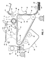
- FIG. 1 schematically depicts an electrophotographic printing machine incorporating the features of the present invention therein. It will become evident from the following discussion that the present invention may be employed in a wide variety of printing machines and is not specifically limited in its application to the particular embodiment depicted herein.
- the electrophotographic printing machine employs a photoconductive belt 10.
- the photoconductive belt 10 is made from a photoconductive material coated on a ground layer, which, in turn, is coated on a anti-curl backing layer.
- the photoconductive material is made from a transport layer coated on a generator layer.
- the transport layer transports positive charges from the generator layer.
- the interface layer is coated on the ground layer.
- the transport layer contains small molecules of di-m-tolydiphenylbiphenyldiamine dispersed in a polycarbonate.
- the generation layer is made from trigonal selenium.
- the grounding layer is made from a titanium coated Mylar. The ground layer is very thin and allows light to pass therethrough.
- Belt 10 moves in the direction of arrow 12 to advance successive portions of the photoconductive surface sequentially through the various processing stations disposed about the path of movement thereof.
- Belt 10 is entrained about stripping roller 14, tensioning roller 16, and drive roller 18.
- Stripping roller 14 is mounted rotatably so as to rotate with belt 10.
- Tensioning roller 16 is resiliently urged against belt 10 to maintain belt 10 under the desired tension.
- Drive roller 18 is rotated by a motor coupled thereto by suitable means such as a belt drive. As roller 18 rotates, it advances belt 10 in the direction of arrow 12.
- Corona generating device 20 includes a generally U-shaped shield and a charging electrode.
- a high voltage power supply 22 is coupled to the shield. A change in the output of power supply 22 causes corona generating device 20 to vary the charge applied to the photoconductive belt 10.
- the charged portion of the photoconductive surface is advanced through imaging station B.
- an original document 24 is positioned face down upon a transparent platen 26.
- One corner of document 24 is located in contact with registration guide 25.
- registration guide 25 With registration guide 25.
- Shutters, indicated generally by the reference numeral 27 move from the home position until the lead edge thereof detects the opposed side edges of the original document.
- the shutters block the platen in the clear portions, i.e. those regions of the platen extending beyond the original document. Further details of the operation of shutters 27 will be described hereinafter with reference to Figures 2 through 4, inclusive.
- Imaging of a document is achieved by lamps 28 which illuminate the document on platen 26. Light rays reflected from the document are transmitted through lens 30. Lens 30 focuses the light image of the original document onto the charged portion of photoconductive belt 10 to selectively dissipate the charge thereon. This records an electrostatic latent image on the photoconductive belt which corresponds to the informational areas contained within the original document.
- a magnetic brush development system advances a developer material into contact with the electrostatic latent image and test patch recorded on photoconductive belt 10.
- magnetic brush development system 34 includes two magnetic brush developer rollers 36 and 38. These rollers each advance the developer material into contact with the latent image and test areas. Each developer roller forms a brush comprising carrier granules and toner particles. The latent image attracts the toner particles from the carrier granules forming a toner powder image on the latent image.
- a toner particle dispenser indicated generally by the reference numeral 40, furnishes additional toner particles to housing 42 for subsequent use by developer rollers 36 and 38, respectively.
- Toner particle dispenser 40 includes a container 44 storing a supply of toner particles therein.
- a foam roller 46 disposed in sump 48 coupled to container 44 dispenses toner particles into an auger 50.
- Auger 50 is made from a helical spring mounted in a tube having a plurality of apertures therein.
- Motor 52 rotates the helical spring to advance the toner particles through the tube so that toner particles are dispensed from the apertures therein. After development, the toner powder image is advanced to transfer station D.
- sheet feeding apparatus 60 includes a feed roll 62 contacting the uppermost sheet of a stack 64 of sheets. Feed rolls 62 rotate so as to advance the uppermost sheet from stack 64 into chute 54. Chute 54 guides the advancing sheet from stack 64 into contact with the photoconductive belt in a timed sequence so that the toner powder image developed thereon contacts the advancing sheet at transfer station D.
- a corona generating device 58 sprays ions onto the backside of sheet 56. This attracts the toner powder image from photoconductive belt 10 to copy sheet 56.
- the copy sheet is separated from belt 10 and a conveyor advances the copy sheet, in the direction of arrow 66, to fusing station E.
- Fusing station E includes a fuser assembly, indicated generally by the reference numeral 68 which permanently affixes the transferred toner powder image to the copy sheet.
- fuser assembly 68 includes a heated fuser roller 70 and a pressure roller 72 with the powder image on the copy sheet contacting fuser roller 70. In this manner, the toner powder image is permanently affixed to sheet 56.
- chute 74 guides the advancing sheet 56 to catch tray 76 for subsequent removal from the printing machine by the operator.
- Cleaning station F includes a rotatably mounted fibrous brush 78 in contact with photoconductive belt 10. The particles are cleaned from photoconductive belt 10 by the rotation of brush 78. Subsequent to cleaning, a discharge lamp (not shown) floods photoconductive belt 10 with light to dissipate any residual electrostatic charge remaining thereon prior to the charging thereof for the next successive imaging cycle.
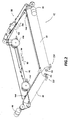
- Shutter 27 includes a front shutter 80 and a side shutter 82.
- Front shutter 80 and side shutter 82 are made from from a flexible, opaque sheet.
- Front shutter 80 is wrapped about front roll 84 with side shutter 82 being wrapped about side roll 86.
- Front motor 88 drives front shutter 80 by rotating front roll 84 and the associated front cable system, indicated generally by the reference numeral 90.
- Front motor 88 rotates in a clockwise and counter clockwise direction so as to move front shutter 80 in the direction of arrows 92 and 94. In this way, front shutter 80 is advanced across platen 26 ( Figure 1), in the direction of arrow 92, so as to position the leading edge thereof adjacent the front edge of original document 24 ( Figure 1).
- front shutter 80 is advanced across platen 26 ( Figure 1), in the direction of arrow 94, so as to position the leading edge thereof at the full open position.
- Side shutter 82 operates in a similar manner.
- Side motor 96 drives side shutter 82 by rotating side roll 86 and the associated side cable system, indicated generally by the reference numeral 98.
- Side motor 96 rotates in a clockwise and counter clockwise direction so as to move side shutter 82 in the direction of arrows 100 and 102.
- side shutter 82 is advanced across platen 26 ( Figure 1), in the direction of arrow 100, so as to position the leading edge thereof adjacent a side edge of original document 24 ( Figure 1) perpendicular to the front edge.
- side shutter 86 is advanced across platen 26 ( Figure 1), in the direction of arrow 102, so as to position the leading edge thereof at the full open position.
- Front document sensor 104 is mounted on the leading edge of front shutter 80.
- Front document sensor 104 includes a light emitting diode and a photodiode.
- front shutter 80 When the light leading edge of front shutter 80 is adjacent the front edge of original document 24, the light rays from the light emitting diode are reflected from the original document and the output from the photodiode changes levels. At this time, front motor 88 is de-energized and the leading edge of front shutter 80 is adjacent the front edge of original document 24.
- Side document sensor 106 is mounted on the leading edge of side shutter 82 Side document sensor 106 also includes a light emitting diode and a photodiode. As side shutter 82 is advanced across platen 26 on the underside thereof in the direction of arrow 100, i.e.
- the shutters are made from flexible sheets which are light reflective. In this way, during exposure of the original document, the charged border regions extending beyond regions of the latent image corresponding to the original document are discharged so as eliminate shadows or black borders on the copy sheet.
- a front shutter clock sensor 108 monitors the distance that the front shutter moves.
- Clock sensor 108 has a disc with a plurality of equally spaced holes about a circle thereon.
- a light emitting diode is located on one side of the disc and a photodiode on the other side thereof. The disc rotates as the front shutter moves in the direction of arrows 92 and 94.
- a pulse is generated corresponding to the change in state of the photodiode, i.e. from not receiving light rays to receiving light rays.
- a circuit is coupled to the photodiode which counts the number of pulses. The number of pulses counted corresponds to the distance that the front shutter has moved. The absolute distance is determined by amplifying the count by the appropriate constant scale factor. The distance that the side shutter moves is determined in substantially the same manner.
- a side shutter clock sensor 110 monitors the distance that the side shutter moves. Clock sensor 110 has a disc with a plurality of equally spaced holes about a circle thereon.
- a light emitting diode is located on one side of the disc and a photodiode on the other side thereof.
- the disc rotates as the side shutter moves in the direction of arrows 100 and 102.
- a pulse is generated corresponding to the change in state of the photodiode, i.e. from not receiving light rays to receiving light rays.
- a circuit is coupled to the photodiode which counts the number of pulses. The number of pulses counted corresponds to the distance that the side shutter has moved. The absolute distance is determined by amplifying the count by the appropriate constant scale factor.
- the shutters are also located in the fully open position. This location is determined by the front and side open position sensors.
- Front open position sensor 112 includes a light emitting diode and a photodiode.
- the front open position sensor is located so that when the leading edge of the front shutter is positioned thereat, the front shutter is fully opened.
- the flexible sheet of the front shutter is interposed between the light emitting diode and the photodiode of front open position sensor 112.
- front shutter 80 moves in the direction of arrow 94, the flexible sheet is interposed between the light emitting diode and photodiode of sensor 112. The light rays from the light emitting diode are blocked by the flexible sheet and the photodiode remains in a low state.
- a circuit connects front open position sensor 112 with front motor 88. Motor 88 is de-energized when the signal from the photodiode of the front open position sensor changes from the low state to the high state. This indicates that the front shutter has reached the fully opened position.
- Side open position sensor 114 includes a light emitting diode and a photodiode. The side open position sensor is located so that when the leading edge of the side shutter is positioned thereat, the side shutter is fully opened.
- the flexible sheet of the side shutter is interposed between the light emitting diode and the photodiode of side open position sensor 114.
- side shutter 82 moves in the direction of arrow 102, the flexible sheet remains interposed between the light emitting diode and photodiode of sensor 114.
- the light rays from the light emitting diode are blocked by the flexible sheet and the photodiode remains in a low state.
- the leading edge of the flexible sheet passes, the light rays from the light emitting diode are transmitted to the photodiode and the output therefrom changes to a high state.
- a circuit connects side open position sensor 114 with side motor 96. Motor 96 is de-energized when the signal from the photodiode of the side open position sensor changes from the low state to the high state. This indicates that the side shutter has reached the fully opened position.
- FIGs 3(a) through 3(c) inclusive the operation of the front and side shutter are depicted thereat.
- shutters 80 and 82 are located in the fully open position. In this position, the entire surface of platen 26 is opened.
- Figure 3(b) shows shutters 82 and 84 covering a portion of platen 26. In operation, the shutters move to the leading edges of the document.
- the corner of the original document defined by mutually perpendicular back and side edges engages the registration guide 25.
- the back edge of the document is opposed to the front edge and the side edge engaging the registration guide is perpendicular thereto forming a corner.
- the registration guide is a corner adapted to receive the corner of the original document.
- Figure 3(c) shows the shutters 82 and 84 positioned adjacent the front and side edges of the original document 24.
- the side and back edges of original document 24 are registered against registration guide 25.
- the shutters are initially located at the full open position ( Figure 3(a)).
- An original document is positioned on the platen and the shutters move to position the leading edges thereof adjacent the front and side edges of the original document ( Figure 3(c)).
- the shutters move to the full open position, as shown in Figure 3(a), and then to the closed position, as shown in Figure 3(b).
- the shutters move to the full open position and the shutters move to position the leading edges thereof adjacent the front and side edges of the document.
- an original document 24 of predetermined size i.e. the length, L, and the width, W, are predetermined, is positioned on the platen in registration with registration guide 25.
- the front shutter advances a distance L′ until the front edge thereof is adjacent the front edge of original document 24.
- the side shutter advances a distance W′ until the side edge thereof is adjacent the side edge of original document 24.
- the distance that the shutters move is determined by clock sensors 108 and 110 ( Figure 1).
- the printing machine of the present invention employs an apparatus for calibrating shutters used therein, and, based upon the calibration information, determining the size of an original document being reproduced therein.
Landscapes
- Physics & Mathematics (AREA)
- General Physics & Mathematics (AREA)
- Exposure Or Original Feeding In Electrophotography (AREA)
- Control Or Security For Electrophotography (AREA)
- Length Measuring Devices By Optical Means (AREA)
- Holders For Sensitive Materials And Originals (AREA)
Applications Claiming Priority (2)
| Application Number | Priority Date | Filing Date | Title |
|---|---|---|---|
| US369876 | 1989-06-22 | ||
| US07/369,876 US4924262A (en) | 1989-06-22 | 1989-06-22 | Shutter calibration and document size detection |
Publications (3)
| Publication Number | Publication Date |
|---|---|
| EP0404566A2 true EP0404566A2 (de) | 1990-12-27 |
| EP0404566A3 EP0404566A3 (de) | 1991-05-08 |
| EP0404566B1 EP0404566B1 (de) | 1994-02-02 |
Family
ID=23457287
Family Applications (1)
| Application Number | Title | Priority Date | Filing Date |
|---|---|---|---|
| EP90306789A Expired - Lifetime EP0404566B1 (de) | 1989-06-22 | 1990-06-21 | Feststellung der Grösse eines Dokuments durch Kalibrierung eines Verschlusses |
Country Status (5)
| Country | Link |
|---|---|
| US (1) | US4924262A (de) |
| EP (1) | EP0404566B1 (de) |
| JP (1) | JPH0337685A (de) |
| CA (1) | CA2017260C (de) |
| DE (1) | DE69006402T2 (de) |
Cited By (1)
| Publication number | Priority date | Publication date | Assignee | Title |
|---|---|---|---|---|
| WO1996018134A1 (de) * | 1994-12-05 | 1996-06-13 | KÖRPERICH, Andreas | Anlegehilfe für eine vorlage an ein kopiergerät |
Families Citing this family (3)
| Publication number | Priority date | Publication date | Assignee | Title |
|---|---|---|---|---|
| JP3370370B2 (ja) * | 1993-02-15 | 2003-01-27 | 株式会社リコー | 光走査型画像読取装置 |
| JP4316317B2 (ja) * | 2003-08-11 | 2009-08-19 | シャープ株式会社 | 画像形成装置の調整方法および画像形成装置 |
| JP4157832B2 (ja) * | 2003-11-20 | 2008-10-01 | 株式会社リコー | 原稿サイズ検知方法及び原稿読取装置及び画像形成装置 |
Family Cites Families (15)
| Publication number | Priority date | Publication date | Assignee | Title |
|---|---|---|---|---|
| JPS54131403A (en) * | 1978-03-31 | 1979-10-12 | Dainippon Screen Mfg | Automatic masking device for original holder of plate making machine |
| JPH0228529Y2 (de) * | 1981-06-19 | 1990-07-31 | ||
| JPS5968728A (ja) * | 1982-10-12 | 1984-04-18 | Canon Inc | 原稿検出装置 |
| US4568181A (en) * | 1982-10-28 | 1986-02-04 | Sharp Kabushiki Kaisha | Size detecting device of a copy document suitable for electrophotographic copying machine |
| ATE30393T1 (de) * | 1982-11-13 | 1987-11-15 | Schuler Gmbh L | Vorrichtung zum elektrischen widerstandsl|ngsnaht-quetschnahtschweissen. |
| US4614874A (en) * | 1983-01-21 | 1986-09-30 | Sharp Kabushiki Kaisha | Original document size detecting arrangement |
| US4585332A (en) * | 1984-08-27 | 1986-04-29 | Xerox Corporation | Electrophotographic printing machine with means for sensing size of document |
| US4659214A (en) * | 1985-02-21 | 1987-04-21 | Mita Industrial Co., Ltd. | Document detecting apparatus |
| US4655585A (en) * | 1985-04-19 | 1987-04-07 | Kabushiki Kaisha Toshiba | Image forming apparatus |
| US4702589A (en) * | 1985-07-04 | 1987-10-27 | Minolta Camera Kabushiki Kaisha | Copying machine that copies halves of a document on different recording medium surfaces |
| JPS629205A (ja) * | 1985-07-05 | 1987-01-17 | Mita Ind Co Ltd | 原稿サイズ検知装置 |
| US4713550A (en) * | 1985-10-08 | 1987-12-15 | Sharp Kabushiki Kaisha | Document size detection apparatus |
| JPS62159972A (ja) * | 1985-12-27 | 1987-07-15 | インタ−ナショナル ビジネス マシ−ンズ コ−ポレ−ション | 文書走査装置 |
| US4823165A (en) * | 1986-11-26 | 1989-04-18 | Sharp Kabushiki Kaisha | Document size detector for copying machine |
| JPS63185741A (ja) * | 1987-01-28 | 1988-08-01 | Minolta Camera Co Ltd | 複写機 |
-
1989
- 1989-06-22 US US07/369,876 patent/US4924262A/en not_active Expired - Lifetime
-
1990
- 1990-05-22 CA CA002017260A patent/CA2017260C/en not_active Expired - Fee Related
- 1990-06-15 JP JP2158543A patent/JPH0337685A/ja active Pending
- 1990-06-21 DE DE69006402T patent/DE69006402T2/de not_active Expired - Fee Related
- 1990-06-21 EP EP90306789A patent/EP0404566B1/de not_active Expired - Lifetime
Cited By (1)
| Publication number | Priority date | Publication date | Assignee | Title |
|---|---|---|---|---|
| WO1996018134A1 (de) * | 1994-12-05 | 1996-06-13 | KÖRPERICH, Andreas | Anlegehilfe für eine vorlage an ein kopiergerät |
Also Published As
| Publication number | Publication date |
|---|---|
| US4924262A (en) | 1990-05-08 |
| EP0404566B1 (de) | 1994-02-02 |
| DE69006402T2 (de) | 1994-06-16 |
| DE69006402D1 (de) | 1994-03-17 |
| CA2017260C (en) | 1996-11-05 |
| JPH0337685A (ja) | 1991-02-19 |
| CA2017260A1 (en) | 1990-12-22 |
| EP0404566A3 (de) | 1991-05-08 |
Similar Documents
| Publication | Publication Date | Title |
|---|---|---|
| US5573236A (en) | Variable sheet guide position sensor | |
| EP0526194B1 (de) | Tonerkonzentrationsermittlung mit Verwendung eines, auf einer Schnecke montierten, Magneten | |
| US5839015A (en) | Paper height measure apparatus for a media tray with linear sensor | |
| US4585332A (en) | Electrophotographic printing machine with means for sensing size of document | |
| CA1096606A (en) | Toner control system for an electrostatic reproduction machine | |
| US4974024A (en) | Predictive toner dispenser controller | |
| EP0492451B1 (de) | Densitometer zur Messung der Markierteilchendichte auf einem Photorezeptor, mit einem Kompensierungsverhältnis zur Anpassung an wechselnde Umgebungsbedingungen und unterschiedliche Maschinen | |
| GB2097965A (en) | Control apparatus for electrostatography | |
| US4326646A (en) | Automatic development dispenser control | |
| US4492179A (en) | Control system for regulating the dispensing of marking particles in an electrophotographic printing machine | |
| US4492321A (en) | Apparatus for dispensing toner particles and sealing the storage chamber thereof | |
| US4980723A (en) | Horizontal image shift by shifting to a slower copying rate | |
| EP0404566B1 (de) | Feststellung der Grösse eines Dokuments durch Kalibrierung eines Verschlusses | |
| US5189475A (en) | Developer mechanism with sensor and notched auger | |
| JPH0467190B2 (de) | ||
| US4447145A (en) | Charged particle sensor | |
| US4731638A (en) | Timing pulse generator for an electrophotographic printing machine | |
| US6640061B2 (en) | Sensing system for detecting a full condition within a waste developer system | |
| US4536080A (en) | Developer material end of life sensing | |
| CA1213638A (en) | Toner concentration monitoring apparatus located behind a transparent photoconductor | |
| US4804996A (en) | Charged particle sensor having magnetic field control | |
| EP0001128B1 (de) | Elektrofotografisches Kopiergerät | |
| US5822662A (en) | Background detection and compensation | |
| JPS6220849Y2 (de) | ||
| US5839017A (en) | Developer level detection system |
Legal Events
| Date | Code | Title | Description |
|---|---|---|---|
| PUAI | Public reference made under article 153(3) epc to a published international application that has entered the european phase |
Free format text: ORIGINAL CODE: 0009012 |
|
| AK | Designated contracting states |
Kind code of ref document: A2 Designated state(s): DE FR GB |
|
| PUAL | Search report despatched |
Free format text: ORIGINAL CODE: 0009013 |
|
| AK | Designated contracting states |
Kind code of ref document: A3 Designated state(s): DE FR GB |
|
| 17P | Request for examination filed |
Effective date: 19911016 |
|
| 17Q | First examination report despatched |
Effective date: 19921106 |
|
| GRAA | (expected) grant |
Free format text: ORIGINAL CODE: 0009210 |
|
| AK | Designated contracting states |
Kind code of ref document: B1 Designated state(s): DE FR GB |
|
| REF | Corresponds to: |
Ref document number: 69006402 Country of ref document: DE Date of ref document: 19940317 |
|
| ET | Fr: translation filed | ||
| PLBE | No opposition filed within time limit |
Free format text: ORIGINAL CODE: 0009261 |
|
| STAA | Information on the status of an ep patent application or granted ep patent |
Free format text: STATUS: NO OPPOSITION FILED WITHIN TIME LIMIT |
|
| 26N | No opposition filed | ||
| REG | Reference to a national code |
Ref country code: GB Ref legal event code: IF02 |
|
| PGFP | Annual fee paid to national office [announced via postgrant information from national office to epo] |
Ref country code: FR Payment date: 20030610 Year of fee payment: 14 |
|
| PGFP | Annual fee paid to national office [announced via postgrant information from national office to epo] |
Ref country code: GB Payment date: 20030618 Year of fee payment: 14 |
|
| PGFP | Annual fee paid to national office [announced via postgrant information from national office to epo] |
Ref country code: DE Payment date: 20030707 Year of fee payment: 14 |
|
| PG25 | Lapsed in a contracting state [announced via postgrant information from national office to epo] |
Ref country code: GB Free format text: LAPSE BECAUSE OF NON-PAYMENT OF DUE FEES Effective date: 20040621 |
|
| PG25 | Lapsed in a contracting state [announced via postgrant information from national office to epo] |
Ref country code: DE Free format text: LAPSE BECAUSE OF NON-PAYMENT OF DUE FEES Effective date: 20050101 |
|
| GBPC | Gb: european patent ceased through non-payment of renewal fee |
Effective date: 20040621 |
|
| PG25 | Lapsed in a contracting state [announced via postgrant information from national office to epo] |
Ref country code: FR Free format text: LAPSE BECAUSE OF NON-PAYMENT OF DUE FEES Effective date: 20050228 |
|
| REG | Reference to a national code |
Ref country code: FR Ref legal event code: ST |