EP0403409B1 - Farmmachine for windrowing products with foldable toolholder arms - Google Patents
Farmmachine for windrowing products with foldable toolholder arms Download PDFInfo
- Publication number
- EP0403409B1 EP0403409B1 EP90440055A EP90440055A EP0403409B1 EP 0403409 B1 EP0403409 B1 EP 0403409B1 EP 90440055 A EP90440055 A EP 90440055A EP 90440055 A EP90440055 A EP 90440055A EP 0403409 B1 EP0403409 B1 EP 0403409B1
- Authority
- EP
- European Patent Office
- Prior art keywords
- pivot
- machine according
- arm
- articulation
- anyone
- Prior art date
- Legal status (The legal status is an assumption and is not a legal conclusion. Google has not performed a legal analysis and makes no representation as to the accuracy of the status listed.)
- Expired - Lifetime
Links
Images


Classifications
-
- A—HUMAN NECESSITIES
- A01—AGRICULTURE; FORESTRY; ANIMAL HUSBANDRY; HUNTING; TRAPPING; FISHING
- A01D—HARVESTING; MOWING
- A01D78/00—Haymakers with tines moving with respect to the machine
- A01D78/08—Haymakers with tines moving with respect to the machine with tine-carrying rotary heads or wheels
- A01D78/10—Haymakers with tines moving with respect to the machine with tine-carrying rotary heads or wheels the tines rotating about a substantially vertical axis
- A01D78/12—Haymakers with tines moving with respect to the machine with tine-carrying rotary heads or wheels the tines rotating about a substantially vertical axis the tines having an additional movement superimposed upon their rotary movement
- A01D78/125—Haymakers with tines moving with respect to the machine with tine-carrying rotary heads or wheels the tines rotating about a substantially vertical axis the tines having an additional movement superimposed upon their rotary movement by a guiding track
-
- Y—GENERAL TAGGING OF NEW TECHNOLOGICAL DEVELOPMENTS; GENERAL TAGGING OF CROSS-SECTIONAL TECHNOLOGIES SPANNING OVER SEVERAL SECTIONS OF THE IPC; TECHNICAL SUBJECTS COVERED BY FORMER USPC CROSS-REFERENCE ART COLLECTIONS [XRACs] AND DIGESTS
- Y10—TECHNICAL SUBJECTS COVERED BY FORMER USPC
- Y10S—TECHNICAL SUBJECTS COVERED BY FORMER USPC CROSS-REFERENCE ART COLLECTIONS [XRACs] AND DIGESTS
- Y10S56/00—Harvesters
- Y10S56/21—Raking and windrowing
Definitions
- the present invention relates to an agricultural machine for swathing products, in particular having a frame which can be connected to a tractor and which comprises at least one rotor rotating around a substantially vertical axis, which rotor has a central housing carrying tool-carrying arms and in which is located a cam which controls said tool-carrying arms so that during each revolution they pivot around their respective geometric axis so that their tools pick up and then deposit the products in the form of a swath , said tool-carrying arms being produced in at least one inner part which is located near the central housing and an outer part which carries the working tools and which is connected to the inner part by means of a hinge around which it can be moved for transport.
- the rotor comprises two arms each having an outer part which can be folded down around an axis transverse to the direction in which the arm concerned extends.
- the two folded arms are brought to the left side of the machine, so as to reduce its width. It is then necessary to block the rotor to prevent these two arms from moving.
- Such a displacement would cause, on the one hand, an upward pivoting of the folded parts due to the control carried out by the cam and, on the other hand, the arrival of non-folded arms on the side of the machine and consequently an increase in width.
- said pivoting of the folded parts of the arms could lead to damage if it encounters the chassis or neighboring arms.
- This embodiment is therefore relatively random.
- it is not suitable for reducing the dimensions of very large machines or front-end machines sufficiently. On these machines, it is practically necessary to shorten all the tool arms in order to reduce both their width and their length for transport.
- each tool holder arm of the rotor has an external part which can be disconnected from an internal part.
- This external part which carries the working tools can be fixed on the chassis of the machine for transport.
- the user is obliged to manually move all the external parts each time the working position is transposed into the transport position and vice versa. Due to the large number of parts to be moved and the weight thereof, this operation is relatively difficult to perform. Consequently, it is to be feared that the transposition will only be carried out for a few arms, which is dangerous when traveling on a road.
- the object of the present invention is a machine with articulated tool-carrying arms not having the drawbacks of known machines.
- an important characteristic of the invention consists in that the articulation between the two parts of each tool-carrying arm of the machine has two pivots, the first of which is substantially directed in the same direction as the internal part of the arm. corresponding and the second is directed so that it forms an angle relative to the first pivot and, that it comprises means for blocking the outer part of each arm relative to its inner part during work.
- each tool-carrying arm In the working position, the two parts of each tool-carrying arm are linked together so that they pivot together as a result of the guidance provided by the control cam.
- each tool-carrying arm For transport, the outer part of each tool-carrying arm is released and is moved around the second pivot, so that it is located substantially on a fictitious circle passing at the ends of the inner parts of the arms.
- the diameter of the rotor is considerably reduced.
- the first pivot allows the outer part of each arm to remain practically stationary relative to the corresponding inner part even if the latter pivots under the action of the control cam.
- This embodiment makes it easy to switch from the working position to the transport position and vice versa.
- the outer parts of the arms do not have to be disassembled or fitted into the inner parts.
- the rotor can rotate without any risk of damage to the folded tool arms.
- Another characteristic of the invention consists in that the interior part of each tool-carrying arm is substantially straight and that the first pivot extends in the extension of this interior part. In this way, the corresponding external part is completely insensitive to the pivoting of the internal part, in the folded position for transport.
- Another characteristic of the invention consists in that, at the articulation between the two parts of each tool-carrying arm, locking means are provided for securing the external part with the corresponding internal part or the pivot integral with this last. These locking means allow in particular to maintain the outer part of each arm in the working position and to rotate it with the corresponding inner part in this position.
- the outer part of each arm has a fixing lug or hook enabling it to be connected to a non-pivoting part of the rotor in the transport position.
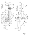
- the machine according to the invention has a frame (1) in the form of a substantially horizontal beam.
- the front end of said frame has three attachment points (2, 3, 4) used for coupling to the hydraulic lifting device of a tractor not shown.
- a swath rotor (5) which can be rotated in the direction of the arrow (F) is connected to the rear end of this frame (1).
- Said rotor (5) is mounted so as to be able to rotate on a substantially vertical support axis (6).
- the upper end of this axis (6) is housed in a housing (7) which is itself articulated on the frame (1) by means of a substantially horizontal axis (8).
- the lower end of the support axis (6) is linked to a T-shaped frame (9) which carries three rollers (10, 11, 12) moving on the ground during work.
- the rotor (5) has a central housing (13) which is mounted on the support axis (6) by means of ball bearings (62). It is located between the casing (7) and the chassis (9). In this housing (13) is located a control cam (14) which is made integral with the support axis (6).
- the upper part of said housing (13) is provided with a toothed crown (15).
- This meshes with a drive pinion (16) which is fixed on a shaft (17) which can be connected, in a known manner, to the PTO shaft of the tractor, by means of shafts transmission (18).
- the crown (15) and the pinion (16) are located in the casing (7) which ensures their protection.
- the housing (13) carries at its periphery bearings (19) in which are housed tool-carrying arms (20), so that they can rotate around their longitudinal geometric axes. These arms (20) extend from the housing (13) in the form of spokes. At their end furthest from said housing, they are provided with tools (21) constituted by raking forks arranged side by side. The other end of each arm (20) is located in the housing (13) and carries a lever (22) provided with a roller (23) which is guided in the control cam (14).
- Each of these tool-carrying arms (20) is made of at least one inner part (24) which is located near the central housing (13) and an outer part (25) which carries the working tools (21).
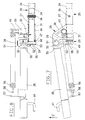
- These two parts (24 and 25) are interconnected by means of a joint (26) having two pivots (27 and 28) (see Figures 3, 4 and 6 to 9).
- the first pivot (27) is oriented substantially in the same direction as the corresponding inner part (24) and the second pivot (28) is directed so that it forms an angle ( ⁇ ) relative to said first pivot.
- locking means (29) for securing the outer part (25) of each arm (20) with its inner part (24) in the working position.
- each articulation (26) is offset relative to each other.
- the second pivot (28) is located in front of the first pivot (27). They are positioned by means of a connecting piece (30).
- This is constituted by two bearings (31 and 32) which are connected together by a tab (33) and each of which has a bore for one of said pivots.
- the inner part (24) of each arm (20) is substantially straight and has at least one hollow end (34).
- the first pivot (27) extends substantially in the extension of this interior part (24).
- This pivot (27) has a cylindrical shape and comprises at one of its ends a stop ring (35). It is engaged in the bore of the bearing (31) of the junction piece (30) and in the hollow end (34) of the inner part (24). It is locked in said inner part by means of a pin (36).
- the second pivot (28) also has a cylindrical shape and has a shoulder (37) at one of its ends. It is housed in the bore of the bearing (32) of the junction piece (30). This bore is directed so that the value of the angle ( ⁇ ) formed by the two pivots (27 and 28) is substantially equal to 90 °.
- the outer part (25) of each arm (20) has at its end which is directed towards the central housing (13) a hinge yoke (38) having orifices through which the second pivot (28) passes.
- each outer part (25) has near its end which is oriented towards the central housing (13) a tab (40) extending in a radial plane.
- This tab (40) has a locking lug (41) which is oriented so that it is substantially parallel to the inner part (24) in the working position.
- the stop ring (35) of the first pivot (27) has an opening whose size roughly corresponds to the section of the ear (41). The latter can thus be engaged in said opening and be stopped relative to the stop ring (35) by means of a pin (42).
- each arm (20) also has at its end opposite the articulation (26) a fixing lug (43) directed approximately perpendicular to the plane in which the working tools (21) extend. ).
- This tab (43) has a hole (44) of elongated shape.
- Each second pivot (28) has at its end which is directed upwards a stud (45) of a height greater than the thickness of the fixing lug (43).
- Each of these fixing lugs (43) can thus be hooked with the corresponding external part (25), to the stud (45) of the pivot (28) of the articulation (26) of the preceding arm (20).
- the distance between the second pivot (28) and the fixing lug (43) of the same outer part (25) is equal to the distance between the second pivots (28) of the different articulations (26).
- the variant embodiment according to FIGS. 7 to 9 includes a large number of parts common with the embodiment described above. These common rooms are designated by the same references.
- the second pivot (28) of each articulation (26) is also offset forward (seen in the direction of rotation (F) of the rotor) relative to the first pivot (27).
- These two pivots (27 and 28) are substantially cylindrical and form an angle ( ⁇ ) of approximately 90 ° between them.
- Said first pivot (27) is engaged in the hollow end (34) of the inner part (24) of the tool holder arm (20) and is locked there by means of a pin (36).
- a connecting piece (30) On the first pivot (27) is mounted a connecting piece (30). This comprises a cylindrical bearing (31) with a bore for mounting on the first pivot (27) and a bearing (32) in the form of a yoke, in which the second pivot (28) is housed.
- the first pivot (27) protrudes from said bearing (31) and comprises in its free end a notch (49).
- each arm (20) has a tip (50) which is located in the yoke formed by the bearing (32) of the connecting piece (30).
- This end piece (50) has a transverse bore through which the second pivot (28) passes. The latter is immobilized axially with circlips (51 and 52).
- Each end piece (50) has a locking tab (53) which extends laterally.
- This tab has a bore (54) whose diameter is slightly greater than that of the first pivot (27).
- a drive (55) of cylindrical shape, which passes right through. In the working position this tab (53) is engaged on the first pivot (27). The end of it is then located in the bore (54) and the driver (55) is housed in the notch (49) ( Figures 7 and 8).
- a tension spring (56) connects the outer part (25) of each tool-carrying arm (20) to the corresponding junction piece (30).
- each outer part (25) has a hooking tab (57).
- the latter is positioned so that the attachment point (58) of the spring (56) is substantially the same distance from the two ends of the outer part (25).
- the connecting piece (30) comprises a boss (59) with a screw (60) which constitutes the point of attachment of the spring (56). This point is located closer to the central housing (13) of the rotor than the second pivot (28) and, seen in the direction of rotation (F), further back than said pivot (28).
- the spring (56) is located above the plane in which the outer part (25) of each arm (20) pivots, around the second pivot (28). In each position of said outer part (25) the spring (56) exerts on it a traction which tends to make it pivot in the direction of the central housing (15) of the rotor.
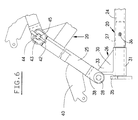
- each support arm tools (20) has near its farthest end a fixing hook (61) used to immobilize it in the transport position.
- each arm (20) In the working position, the outer part (25) of each arm (20) according to the first embodiment described extends more or less in the extension of the corresponding inner part (24). It is blocked relative to said inner part by means of the lug (41) which is immobilized in the stop ring (35). In this position, the tab (40) bears against this stop ring (35).
- the central housing (13) is rotated through the ring gear (15) and the pinion (16), in the direction of the arrow (F), the rollers (23) of the levers (22) which are connected to the internal parts (24) move in the cam (14).
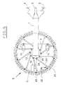
- each outer part (25) is then moved around its second pivot (28), in the direction of the central box (13), until its fixing lug (43) can be fixed on the stud (45) of the second pivot (28) of the preceding arm (20) (FIGS. 5 and 6). It can then be immobilized by means of the pin (42) which can be engaged in a hole provided in said stud. In this position, these outer parts (25) are no longer controlled by the cam (14). It is apparent in particular from FIG. 5 that all of these exterior parts (25) are situated practically on a fictitious circle (C) passing at the ends (34) of the interior parts (24) of the arms (20). The dimensions of the rotor (5) are thus considerably reduced on all sides, so that the machine can easily be transported. In this position, it will also occupy less space during storage during the period of non-use.
- the external part (25) of each tool-carrying arm (20) is held in the working position and in the transport position by the tension spring (56).
- said outer part (25) extends substantially in the same direction as the corresponding inner part (24).
- Its locking tab (53) is located on the end of the first pivot (27).
- the trainer (55) is then housed in the notch (49) and thus ensures a positive connection between the two parts (24 and 25).
- the pivoting of the inner part (24), which results from the movement of its roller (23) in the control cam (14) is then transmitted to the outer part (25) so that its tools (21) swath the lying plants On the ground. In this position the pressure of the plants on said tools (21) adds to the action of the spring (56) and helps to maintain the outer part (25) of each arm (20) in the working position.
- each arm (20) For transportation, the outer part (25) of each arm (20) is moved around the second pivot (28) in the direction of rotation (F), towards the central box (13). First, the spring (56) is stretched. Then, as soon as it has passed over the second corresponding pivot (28), it contracts and pulls the outer part (25) in the direction of the central housing (13) of the rotor. The hook (61) is then placed between two ribs of the junction piece (30) of the articulation (26) of the preceding tool-carrying arm (20). The outer parts (25) of all the arms (20) are then folded over the fictitious circle (C) shown in Figure 5. Any pivoting of the inner parts (24) is no longer transmitted to the outer parts (25) and the rotor diameter is significantly reduced.
Abstract
Description
La présente invention se rapporte à une machine agricole pour l'andainage de produits, présentant notamment un bâti qui peut être relié à un tracteur et qui comporte au moins un rotor tournant autour d'un axe sensiblement vertical, lequel rotor possède un boîtier central portant des bras porte-outils et dans lequel se situe une came qui commande lesdits bras porte-outils de telle sorte que durant chaque révolution ils pivotent autour de leur axe géométrique respectif afin que leurs outils ramassent puis déposent les produits sous la forme d'un andain, lesdits bras porte-outils étant réalisés en au moins une partie intérieure qui se situe près du boîtier central et une partie extérieure qui porte les outils de travail et qui est reliée à la partie intérieure au moyen d'une articulation autour de laquelle elle peut être déplacée pour le transport.The present invention relates to an agricultural machine for swathing products, in particular having a frame which can be connected to a tractor and which comprises at least one rotor rotating around a substantially vertical axis, which rotor has a central housing carrying tool-carrying arms and in which is located a cam which controls said tool-carrying arms so that during each revolution they pivot around their respective geometric axis so that their tools pick up and then deposit the products in the form of a swath , said tool-carrying arms being produced in at least one inner part which is located near the central housing and an outer part which carries the working tools and which is connected to the inner part by means of a hinge around which it can be moved for transport.
Sur une machine de ce genre, connue dans le brevet FR 2 355 440, le rotor comporte deux bras ayant chacun une partie extérieure repliable vers le bas autour d'un axe transversal à la direction dans laquelle s'étend le bras concerné. Pour le transport, les deux bras repliés sont amenés sur le côté gauche de la machine, de manière à réduire sa largeur. Il est alors nécessaire de bloquer le rotor pour éviter que ces deux bras ne se déplacent. Un tel déplacement provoquerait, d'une part, un pivotement vers le haut des parties repliées en raison de la commande effectuée par la came et, d'autre part, l'arrivée de bras non repliés sur le côté de la machine et par conséquent une augmentation de la largeur. En sus, ledit pivotement des parties repliées des bras pourrait entraîner des détériorations en cas de rencontre avec le châssis ou les bras voisins. Ce mode de réalisation est donc relativement aléatoire. De plus, il ne convient pas pour réduire suffisamment les dimensions des très grandes machines ou bien des machines frontales. Sur ces machines, il est pratiquement nécessaire de raccourcir tous les bras porte-outils afin de réduire à la fois leur largeur et leur longueur pour le transport.On a machine of this kind, known in
Sur une autre machine connue, tous les bras porte-outils du rotor sont réalisés en deux parties téléscopiques. Pour le transport, les parties extérieures des bras sont glissées vers l'intérieur en vue de réduire le diamètre du rotor. Cet agencement est cependant très fragile. Ledit glissement de la partie extérieure est rapidement freiné voire empêché par la terre ou les débris végétaux qui peuvent s'y coller, par la rouille qui peut se former ou par des déformations, même légères, qui peuvent résulter de chocs subis par les bras. Pour ces différentes raisons, cette solution ne convient guère pour le réglage des bras sur les machines agricoles destinées à l'andainage.On another known machine, all the tool-carrying arms of the rotor are produced in two telescopic parts. For transport, the outer parts of the arms are slid inwards in order to reduce the diameter of the rotor. This arrangement is however very fragile. Said sliding of the external part is quickly braked or even prevented by the earth or the plant debris which can stick to it, by the rust which can form or by deformations, even slight, which can result from shocks undergone by the arms. For these various reasons, this solution is hardly suitable for adjusting the arms on agricultural machines intended for swathing.
Sur une autre machine connue, chaque bras porte-outils du rotor comporte une partie extérieure déconnectable d'une partie intérieure. Cette partie extérieure qui porte les outils de travail peut être fixée sur le châssis de la machine en vue du transport. Dans ce cas, l'utilisateur est obligé de déplacer manuellement toutes les parties extérieures lors de chaque transposition de la position de travail dans la position de transport et vice-versa. En raison du grand nombre de pièces à déplacer et du poids de celles-ci, cette opération est relativement pénible à effectuer. Par conséquent, il est à craindre que la transposition ne soit réalisée que pour quelques bras, ce qui est dangereux en cas de déplacement sur une route.On another known machine, each tool holder arm of the rotor has an external part which can be disconnected from an internal part. This external part which carries the working tools can be fixed on the chassis of the machine for transport. In this case, the user is obliged to manually move all the external parts each time the working position is transposed into the transport position and vice versa. Due to the large number of parts to be moved and the weight thereof, this operation is relatively difficult to perform. Consequently, it is to be feared that the transposition will only be carried out for a few arms, which is dangerous when traveling on a road.
La présente invention a pour but une machine avec des bras porte-outils articulés n'ayant pas les inconvénients des machines connues.The object of the present invention is a machine with articulated tool-carrying arms not having the drawbacks of known machines.
A cet effet, une importante caractéristique de l'invention consiste en ce que l'articulation entre les deux parties de chaque bras porte-outils de la machine présente deux pivots dont le premier est sensiblement dirigé dans la même direction que la partie intérieure du bras correspondant et le second est dirigé de telle sorte qu'il forme un angle par rapport au premier pivot et, qu'elle comporte des moyens de blocage de la partie extérieure de chaque bras par rapport à sa partie intérieure durant le travail.To this end, an important characteristic of the invention consists in that the articulation between the two parts of each tool-carrying arm of the machine has two pivots, the first of which is substantially directed in the same direction as the internal part of the arm. corresponding and the second is directed so that it forms an angle relative to the first pivot and, that it comprises means for blocking the outer part of each arm relative to its inner part during work.
Dans la position de travail, les deux parties de chaque bras porte-outils sont liées entre elles de sorte qu'elles pivotent ensemble par suite du guidage assuré par la came de commande.In the working position, the two parts of each tool-carrying arm are linked together so that they pivot together as a result of the guidance provided by the control cam.
Pour le transport, la partie extérieure de chaque bras porte-outils est débloquée et est déplacée autour du second pivot, de telle sorte qu'elle se situe sensiblement sur un cercle fictif passant au niveau des extrémités des parties intérieures des bras. Lorsque toutes les parties extérieures des bras porte-outils sont repliées tel que décrit ci-dessus, le diamètre du rotor est considérablement réduit. Dans cette nouvelle position, le premier pivot permet à la partie extérieure de chaque bras de rester pratiquement immobile par rapport à la partie intérieure correspondante même si celle-ci pivote sous l'action de la came de commande.For transport, the outer part of each tool-carrying arm is released and is moved around the second pivot, so that it is located substantially on a fictitious circle passing at the ends of the inner parts of the arms. When all the external parts of the tool arms are folded as described above, the diameter of the rotor is considerably reduced. In this new position, the first pivot allows the outer part of each arm to remain practically stationary relative to the corresponding inner part even if the latter pivots under the action of the control cam.
Ce mode de réalisation permet de passer aisément de la position de travail dans la position de transport et vice-versa. Les parties extérieures des bras n'ont pas besoin d'être démontées ou d'être emboîtées dans les parties intérieures. En sus, le rotor peut tourner sans qu'il y ait un risque d'endommagement des bras porte-outils repliés.This embodiment makes it easy to switch from the working position to the transport position and vice versa. The outer parts of the arms do not have to be disassembled or fitted into the inner parts. In addition, the rotor can rotate without any risk of damage to the folded tool arms.
Une autre caractéristique de l'invention consiste en ce que la partie intérieure de chaque bras porte-outils est sensiblement droite et que le premier pivot s'étend dans le prolongement de cette partie intérieure. De cette manière, la partie extérieure correspondante est totalement insensible aux pivotements de la partie intérieure, dans la position repliée pour le transport.Another characteristic of the invention consists in that the interior part of each tool-carrying arm is substantially straight and that the first pivot extends in the extension of this interior part. In this way, the corresponding external part is completely insensitive to the pivoting of the internal part, in the folded position for transport.
Une autre caractéristique de l'invention consiste en ce que, au niveau de l'articulation entre les deux parties de chaque bras porte-outils sont prévus des moyens de blocage pour solidariser la partie extérieure avec la partie intérieure correspondante ou le pivot solidaire de cette dernière. Ces moyens de blocage permettent notamment de maintenir la partie extérieure de chaque bras en position de travail et de la faire pivoter avec la partie intérieure correspondante dans cette position.Another characteristic of the invention consists in that, at the articulation between the two parts of each tool-carrying arm, locking means are provided for securing the external part with the corresponding internal part or the pivot integral with this last. These locking means allow in particular to maintain the outer part of each arm in the working position and to rotate it with the corresponding inner part in this position.
Selon une autre caractéristique de l'invention, la partie extérieure de chaque bras comporte une patte ou un crochet de fixation permettant de la relier à une partie non pivotante du rotor dans la position de transport.According to another characteristic of the invention, the the outer part of each arm has a fixing lug or hook enabling it to be connected to a non-pivoting part of the rotor in the transport position.
D'autres caractéristiques et avantages de l'invention ressortiront des revendications et de la description ci-après des exemples de réalisation non limitatifs de l'invention, avec référence aux dessins annexés dans lesquels :
- la figure 1 représente une vue de dessus d'une machine selon l'invention dans la position de travail,
- la figure 2 représente une vue de côté, partiellement en coupe, de la machine selon la figure 1,
- la figure 3 représente, à plus grande échelle, une vue de dessus de l'articulation d'un bras porte-outils dans la position de travail,
- la figure 4 représente une vue de face, avec une coupe partielle, de cette articulation,
- la figure 5 représente une vue de dessus de la machine selon l'invention dans la position de transport,
- la figure 6 représente une vue de détail de l'articulation d'un bras porte-outils dans la position de transport,
- la figure 7 représente une vue de dessus d'une variante de réalisation de l'articulation d'un bras porte-outils en position de travail,
- la figure 8 représente une vue de face, avec une coupe partielle, de cette variante de réalisation,
- la figure 9 représente une vue de dessus de cette variante de réalisation, dans la position de transport.
- FIG. 1 represents a top view of a machine according to the invention in the working position,
- FIG. 2 represents a side view, partially in section, of the machine according to FIG. 1,
- FIG. 3 represents, on a larger scale, a top view of the articulation of a tool-carrying arm in the working position,
- FIG. 4 represents a front view, with a partial section, of this articulation,
- FIG. 5 represents a top view of the machine according to the invention in the transport position,
- FIG. 6 represents a detailed view of the articulation of a tool-carrying arm in the transport position,
- FIG. 7 represents a top view of an alternative embodiment of the articulation of a tool-carrying arm in the working position,
- FIG. 8 represents a front view, with a partial section, of this alternative embodiment,
- FIG. 9 represents a top view of this alternative embodiment, in the transport position.
Telle qu'elle est représentée sur les figures 1 et 2 la machine selon l'invention possède un bâti (1) en forme de poutre sensiblement horizontale. L'extrémité avant dudit bâti comporte trois points d'accrochage (2, 3, 4) servant à l'accouplement au dispositif de relevage hydraulique d'un tracteur non représenté. Un rotor d'andainage (5) qui peut être entraîné en rotation dans le sens de la flèche (F) est relié à l'extrémité arrière de ce bâti (1).As shown in Figures 1 and 2 the machine according to the invention has a frame (1) in the form of a substantially horizontal beam. The front end of said frame has three attachment points (2, 3, 4) used for coupling to the hydraulic lifting device of a tractor not shown. A swath rotor (5) which can be rotated in the direction of the arrow (F) is connected to the rear end of this frame (1).
Ledit rotor (5) est monté de manière à pouvoir tourner sur un axe support sensiblement vertical (6). L'extrémité supérieure de cet axe (6) est logée dans un carter (7) qui est lui-même articulé sur le bâti (1) au moyen d'un axe (8) sensiblement horizontal. L'extrémité inférieure de l'axe support (6) est liée à un châssis (9) en forme de T qui porte trois roulettes (10, 11, 12) se déplaçant sur le sol durant le travail. Le rotor (5) possède un boîtier central (13) qui est monté sur l'axe support (6) au moyen de roulements à billes (62). Il se situe entre le carter (7) et le châssis (9). Dans ce boîtier (13) se situe une came de commande (14) qui est rendue solidaire de l'axe support (6). La partie supérieure dudit boîtier (13) est munie d'une couronne dentée (15). Celle-ci engrène avec un pignon d'entraînement (16) qui est fixé sur un arbre (17) pouvant être relié, d'une manière connue, à l'arbre de prise de force du tracteur, par l'intermédiaire d'arbres de transmission (18). La couronne (15) et le pignon (16) se situent dans le carter (7) qui assure leur protection.Said rotor (5) is mounted so as to be able to rotate on a substantially vertical support axis (6). The upper end of this axis (6) is housed in a housing (7) which is itself articulated on the frame (1) by means of a substantially horizontal axis (8). The lower end of the support axis (6) is linked to a T-shaped frame (9) which carries three rollers (10, 11, 12) moving on the ground during work. The rotor (5) has a central housing (13) which is mounted on the support axis (6) by means of ball bearings (62). It is located between the casing (7) and the chassis (9). In this housing (13) is located a control cam (14) which is made integral with the support axis (6). The upper part of said housing (13) is provided with a toothed crown (15). This meshes with a drive pinion (16) which is fixed on a shaft (17) which can be connected, in a known manner, to the PTO shaft of the tractor, by means of shafts transmission (18). The crown (15) and the pinion (16) are located in the casing (7) which ensures their protection.
Le boîtier (13) porte à sa périphérie des paliers (19) dans lesquels sont logés des bras porte-outils (20), de manière à ce qu'ils puissent pivoter autour de leurs axes géométriques longitudinaux. Ces bras (20) s'étendent à partir du boîtier (13) en forme de rayons. A leur extrémité la plus éloignée dudit boîtier, ils sont munis d'outils (21) constitués par des fourches de râtelage disposées côte à côte. L'autre extrémité de chaque bras (20) se situe dans le boîtier (13) et porte un levier (22) muni d'un galet (23) qui est guidé dans la came de commande (14).The housing (13) carries at its periphery bearings (19) in which are housed tool-carrying arms (20), so that they can rotate around their longitudinal geometric axes. These arms (20) extend from the housing (13) in the form of spokes. At their end furthest from said housing, they are provided with tools (21) constituted by raking forks arranged side by side. The other end of each arm (20) is located in the housing (13) and carries a lever (22) provided with a roller (23) which is guided in the control cam (14).
Chacun de ces bras porte-outils (20) est réalisé en au moins une partie intérieure (24) qui se situe près du boîtier central (13) et une partie extérieure (25) qui porte les outils de travail (21). Ces deux parties (24 et 25) sont reliées entre elles au moyen d'une articulation (26) présentant deux pivots (27 et 28) (voir figures 3, 4 et 6 à 9). Le premier pivot (27) est sensiblement dirigé dans la même direction que la partie intérieure (24) correspondante et le second pivot (28) est dirigé de telle sorte qu'il forme un angle (α) par rapport audit premier pivot. Au niveau de cette articulation (26) sont, en sus, prévus des moyens de blocage (29) pour solidariser la partie extérieure (25) de chaque bras (20) avec sa partie intérieure (24) dans la position de travail.Each of these tool-carrying arms (20) is made of at least one inner part (24) which is located near the central housing (13) and an outer part (25) which carries the working tools (21). These two parts (24 and 25) are interconnected by means of a joint (26) having two pivots (27 and 28) (see Figures 3, 4 and 6 to 9). The first pivot (27) is oriented substantially in the same direction as the corresponding inner part (24) and the second pivot (28) is directed so that it forms an angle (α) relative to said first pivot. At this articulation (26) are, in addition, provided locking means (29) for securing the outer part (25) of each arm (20) with its inner part (24) in the working position.
Dans le mode de réalisation représenté sur les figures 1 à 6, les deux pivots (27 et 28) de chaque articulation (26) sont décalés l'un par rapport à l'autre. Vu dans le sens de rotation (F) le second pivot (28) se situe devant le premier pivot (27). Ils sont positionnés au moyen d'une pièce de jonction (30). Celle-ci est constituée par deux paliers (31 et 32) qui sont reliés entre eux par une patte (33) et dont chacun présente un alésage pour un desdits pivots. On voit par ailleurs que la partie intérieure (24) de chaque bras (20) est sensiblement droite et comporte au moins une extrémité creuse (34). Le premier pivot (27) s'étend sensiblement dans le prolongement de cette partie intérieure (24). Ce pivot (27) a une forme cylindrique et comporte à l'une de ses extrémités une bague d'arrêt (35). Il est engagé dans l'alésage du palier (31) de la pièce de jonction (30) et dans l'extrémité creuse (34) de la partie intérieure (24). Il est bloqué dans ladite partie intérieure au moyen d'une goupille (36).In the embodiment shown in Figures 1 to 6, the two pivots (27 and 28) of each articulation (26) are offset relative to each other. Seen in the direction of rotation (F) the second pivot (28) is located in front of the first pivot (27). They are positioned by means of a connecting piece (30). This is constituted by two bearings (31 and 32) which are connected together by a tab (33) and each of which has a bore for one of said pivots. It can also be seen that the inner part (24) of each arm (20) is substantially straight and has at least one hollow end (34). The first pivot (27) extends substantially in the extension of this interior part (24). This pivot (27) has a cylindrical shape and comprises at one of its ends a stop ring (35). It is engaged in the bore of the bearing (31) of the junction piece (30) and in the hollow end (34) of the inner part (24). It is locked in said inner part by means of a pin (36).
Le deuxième pivot (28) a également une forme cylindrique et comporte à l'une de ses extrémités un épaulement (37). Il est logé dans l'alésage du palier (32) de la pièce de jonction (30). Cet alésage est dirigé de telle sorte que la valeur de l'angle (α ) que forment entre eux les deux pivots (27 et 28) est sensiblement égale à 90°. La partie extérieure (25) de chaque bras (20) comporte à son extrémité qui est dirigée vers le boîtier central (13) une chape d'articulation (38) présentant des orifices dans lesquels passe le second pivot (28). Ce dernier est arrêté axialement au moyen de l'épaulement (37) qui se situe d'un côté par rapport au palier (32) et à la chape d'articulation (38) et, d'un circlips (39) monté sur l'extrémité du pivot (28) située de l'autre côté par rapport à ces mêmes pièces (voir figure 4).The second pivot (28) also has a cylindrical shape and has a shoulder (37) at one of its ends. It is housed in the bore of the bearing (32) of the junction piece (30). This bore is directed so that the value of the angle (α) formed by the two pivots (27 and 28) is substantially equal to 90 °. The outer part (25) of each arm (20) has at its end which is directed towards the central housing (13) a hinge yoke (38) having orifices through which the second pivot (28) passes. The latter is stopped axially by means of the shoulder (37) which is situated on one side with respect to the bearing (32) and to the articulation yoke (38) and, with a circlip (39) mounted on the end of the pivot (28) located on the other side with respect to these same parts (see Figure 4).
Les moyens (29) pour bloquer l'une par rapport à l'autre les deux parties (24 et 25) de chaque bras (20) sont clairement visibles sur les figures 3 et 4. Chaque partie extérieure (25) comporte près de son extrémité qui est orientée vers le boîtier central (13) une patte (40) s'étendant dans un plan radial. Cette patte (40) possède une oreille de blocage (41) qui est orientée de façon à ce qu'elle soit sensiblement parallèle à la partie intérieure (24) dans la position de travail. La bague d'arrêt (35) du premier pivot (27) présente une ouverture dont la taille correspond à peu près à la section de l'oreille (41). Celle-ci peut ainsi être engagée dans ladite ouverture et être arrêtée par rapport à la bague d'arrêt (35) au moyen d'une goupille (42).The means (29) for blocking one with respect to the other the two parts (24 and 25) of each arm (20) are clearly visible in Figures 3 and 4. Each outer part (25) has near its end which is oriented towards the central housing (13) a tab (40) extending in a radial plane. This tab (40) has a locking lug (41) which is oriented so that it is substantially parallel to the inner part (24) in the working position. The stop ring (35) of the first pivot (27) has an opening whose size roughly corresponds to the section of the ear (41). The latter can thus be engaged in said opening and be stopped relative to the stop ring (35) by means of a pin (42).
La partie extérieure (25) de chaque bras (20) comporte également à son extrémité opposée à l'articulation (26) une patte de fixation (43) dirigée à peu près perpendiculairement au plan dans lequel s'étendent les outils de travail (21). Cette patte (43) comporte un trou (44) de forme allongée. Chaque second pivot (28) comporte à son extrémité qui est dirigée vers le haut un téton (45) d'une hauteur supérieure à l'épaisseur de la patte de fixation (43). Chacune de ces pattes de fixation (43) peut ainsi être accrochée avec la partie extérieure (25) correspondante, au téton (45) du pivot (28) de l'articulation (26) du bras (20) précédent. Pour cela la distance entre le second pivot (28) et la patte de fixation (43) d'une même partie extérieure (25) est égale à la distance entre les seconds pivots (28) des différentes articulations (26).The outer part (25) of each arm (20) also has at its end opposite the articulation (26) a fixing lug (43) directed approximately perpendicular to the plane in which the working tools (21) extend. ). This tab (43) has a hole (44) of elongated shape. Each second pivot (28) has at its end which is directed upwards a stud (45) of a height greater than the thickness of the fixing lug (43). Each of these fixing lugs (43) can thus be hooked with the corresponding external part (25), to the stud (45) of the pivot (28) of the articulation (26) of the preceding arm (20). For this, the distance between the second pivot (28) and the fixing lug (43) of the same outer part (25) is equal to the distance between the second pivots (28) of the different articulations (26).
La variante de réalisation selon les figures 7 à 9 comporte un grand nombre de pièces communes avec le mode de réalisation décrit ci-avant. Ces pièces communes sont désignées par les mêmes repères. Dans cette variante le second pivot (28) de chaque articulation (26) est également décalé vers l'avant (vu dans le sens de rotation (F) du rotor) par rapport au premier pivot (27). Ces deux pivots (27 et 28) sont sensiblement cylindriques et forment un angle (α) d'environ 90° entre eux. Ledit premier pivot (27) est engagé dans l'extrémité creuse (34) de la partie intérieure (24) du bras porte-outils (20) et y est bloqué au moyen d'une goupille (36). Sur le premier pivot (27) est montée une pièce de jonction (30). Celle-ci comporte un palier cylindrique (31) avec un alésage pour le montage sur le premier pivot (27) et un palier (32) en forme de chape, dans lequel est logé le second pivot (28).The variant embodiment according to FIGS. 7 to 9 includes a large number of parts common with the embodiment described above. These common rooms are designated by the same references. In this variant, the second pivot (28) of each articulation (26) is also offset forward (seen in the direction of rotation (F) of the rotor) relative to the first pivot (27). These two pivots (27 and 28) are substantially cylindrical and form an angle (α) of approximately 90 ° between them. Said first pivot (27) is engaged in the hollow end (34) of the inner part (24) of the tool holder arm (20) and is locked there by means of a pin (36). On the first pivot (27) is mounted a connecting piece (30). This comprises a cylindrical bearing (31) with a bore for mounting on the first pivot (27) and a bearing (32) in the form of a yoke, in which the second pivot (28) is housed.
Dans l'alésage du palier (31) sont prévues des bagues (46) pour faciliter la rotation du pivot (27) par rapport à la pièce de jonction (30). Celle-ci est bloquée dans le sens axial sur le pivot (27), d'un côté, par la partie intérieure (24) et, de l'autre côté, par une rondelle (47) et un circlips (48). Le premier pivot (27) dépasse dudit palier (31) et comporte dans son extrémité libre une entaille (49).In the bore of the bearing (31) are provided rings (46) to facilitate rotation of the pivot (27) relative to the connecting piece (30). This is locked axially on the pivot (27), on one side, by the inner part (24) and, on the other side, by a washer (47) and a circlip (48). The first pivot (27) protrudes from said bearing (31) and comprises in its free end a notch (49).
La partie extérieure (25) de chaque bras (20) comporte un embout (50) qui se situe dans la chape formée par le palier (32) de la pièce de jonction (30). Cet embout (50) présente un alésage transversal à travers lequel passe le second pivot (28). Ce dernier est immobilisé axialement avec des circlips (51 et 52).The outer part (25) of each arm (20) has a tip (50) which is located in the yoke formed by the bearing (32) of the connecting piece (30). This end piece (50) has a transverse bore through which the second pivot (28) passes. The latter is immobilized axially with circlips (51 and 52).
Chaque embout (50) comporte une patte de blocage (53) qui s'étend latéralement. Cette patte présente un alésage (54) dont le diamètre est légèrement supérieur à celui du premier pivot (27). Dans cet alésage (54) est prévu un entraineur (55) de forme cylindrique, qui le traverse de part en part. Dans la position de travail cette patte (53) est engagée sur le premier pivot (27). L'extrémité de celui-ci se situe alors dans l'alésage (54) et l'entraineur (55) est logé dans l'entaille (49) (figures 7 et 8).Each end piece (50) has a locking tab (53) which extends laterally. This tab has a bore (54) whose diameter is slightly greater than that of the first pivot (27). In this bore (54) is provided a drive (55) of cylindrical shape, which passes right through. In the working position this tab (53) is engaged on the first pivot (27). The end of it is then located in the bore (54) and the driver (55) is housed in the notch (49) (Figures 7 and 8).
Un ressort de traction (56) relie la partie extérieure (25) de chaque bras porte-outils (20) à la pièce de jonction (30) correspondante. A cet effet, chaque partie extérieure (25) comporte une patte d'accrochage (57). Celle-ci est positionnée de telle sorte que le point d'accrochage (58) du ressort (56) se trouve sensiblement à la même distance des deux extrémités de la partie extérieure (25). La pièce de jonction (30) comporte un bossage (59) avec une vis (60) qui constitue le point d'accrochage du ressort (56). Ce point se situe plus près du boîtier central (13) du rotor que le second pivot (28) et, vu dans le sens de rotation (F), plus en arrière que ledit pivot (28). Le ressort (56) se situe en sus au-dessus du plan dans lequel pivote la partie extérieure (25) de chaque bras (20), autour du second pivot (28). Dans chaque position de ladite partie extérieure (25) le ressort (56) exerce sur elle une traction qui tend à la faire pivoter en direction du boîtier central (15) du rotor.A tension spring (56) connects the outer part (25) of each tool-carrying arm (20) to the corresponding junction piece (30). To this end, each outer part (25) has a hooking tab (57). The latter is positioned so that the attachment point (58) of the spring (56) is substantially the same distance from the two ends of the outer part (25). The connecting piece (30) comprises a boss (59) with a screw (60) which constitutes the point of attachment of the spring (56). This point is located closer to the central housing (13) of the rotor than the second pivot (28) and, seen in the direction of rotation (F), further back than said pivot (28). The spring (56) is located above the plane in which the outer part (25) of each arm (20) pivots, around the second pivot (28). In each position of said outer part (25) the spring (56) exerts on it a traction which tends to make it pivot in the direction of the central housing (15) of the rotor.
La partie extérieure (25) de chaque bras porte- outils (20) comporte près de son extrémité la plus éloignée un crochet de fixation (61) servant à l'immobiliser dans la position de transport.The outer part (25) of each support arm tools (20) has near its farthest end a fixing hook (61) used to immobilize it in the transport position.
Dans la position de travail la partie extérieure (25) de chaque bras (20) selon le premier mode de réalisation décrit s'étend plus ou moins dans le prolongement de la partie intérieure (24) correspondante. Elle est bloquée par rapport à ladite partie intérieure au moyen de l'oreille (41) qui est immobilisée dans la bague d'arrêt (35). Dans cette position, la patte (40) s'appuie contre cette bague d'arrêt (35). Lorsque le boîtier central (13) est entraîné en rotation à travers la couronne dentée (15) et le pignon (16), dans le sens de la flèche (F), les galets (23) des leviers (22) qui sont reliés aux parties intérieures (24) se déplacent dans la came (14).
Celle-ci commande alors les deux parties (24 et 25) des bras (20) pour que durant chaque révolution ils pivotent autour de leurs axes géométriques, de telle sorte que dans la partie avant de leur trajectoire, les outils (21) soient dirigés vers le sol et ramassent les produits, par exemple du fourrage, couchés sur le sol et que dans la partie latérale de leur trajectoire, lesdits outils se lèvent et déposent les produits ramassés sous la forme d'un andain.In the working position, the outer part (25) of each arm (20) according to the first embodiment described extends more or less in the extension of the corresponding inner part (24). It is blocked relative to said inner part by means of the lug (41) which is immobilized in the stop ring (35). In this position, the tab (40) bears against this stop ring (35). When the central housing (13) is rotated through the ring gear (15) and the pinion (16), in the direction of the arrow (F), the rollers (23) of the levers (22) which are connected to the internal parts (24) move in the cam (14).
This then controls the two parts (24 and 25) of the arms (20) so that during each revolution they pivot around their geometric axes, so that in the front part of their trajectory, the tools (21) are directed towards the ground and collect the products, for example fodder, lying on the ground and that in the lateral part of their trajectory, said tools rise and deposit the products collected in the form of a swath.
Pour le transport, l'oreille (41) de la partie extérieure (25) de chaque bras (20) est débloquée par l'opérateur. Chaque partie extérieure (25) est alors déplacée autour de son second pivot (28), en direction du boîtier central (13), jusqu'a ce que sa patte de fixation (43) puisse être fixée sur le téton (45) du second pivot (28) du bras (20) précédent (figures 5 et 6). Elle peut alors être immobilisée au moyen de la goupille (42) qui peut être engagée dans un trou prévu dans ledit téton. Dans cette position, ces parties extérieures (25) ne sont plus commandées par la came (14). Il ressort notamment de la figure 5 que toutes ces parties extérieures (25) se situent pratiquement sur un cercle fictif (C) passant au niveau des extrémités (34) des parties intérieures (24) des bras (20). Les dimensions du rotor (5) sont ainsi considérablement réduites sur tous les côtés, de sorte que la machine puisse aisément être transportée. Dans cette position, elle occupera également moins de place lors du rangement pendant la période de non-utilisation.For transport, the ear (41) of the outer part (25) of each arm (20) is released by the operator. Each outer part (25) is then moved around its second pivot (28), in the direction of the central box (13), until its fixing lug (43) can be fixed on the stud (45) of the second pivot (28) of the preceding arm (20) (FIGS. 5 and 6). It can then be immobilized by means of the pin (42) which can be engaged in a hole provided in said stud. In this position, these outer parts (25) are no longer controlled by the cam (14). It is apparent in particular from FIG. 5 that all of these exterior parts (25) are situated practically on a fictitious circle (C) passing at the ends (34) of the interior parts (24) of the arms (20). The dimensions of the rotor (5) are thus considerably reduced on all sides, so that the machine can easily be transported. In this position, it will also occupy less space during storage during the period of non-use.
Dans la variante de réalisation selon les figures 7 à 9 la partie extérieure (25) de chaque bras porte-outils (20) est maintenue en position de travail et en position de transport par le ressort de traction (56). Pour le travail, ladite partie extérieure (25) s'étend sensiblement dans la même direction que la partie intérieure (24) correspondante. Sa patte de blocage (53) se situe sur l'extrémité du premier pivot (27). L'entraineur (55) est alors logé dans l'entaille (49) et assure ainsi une liaison positive entre les deux parties (24 et 25). Le pivotement de la partie intérieure (24), qui résulte du déplacement de son galet (23) dans la came de commande (14) est alors transmis à la partie extérieure (25) de sorte que ses outils (21) andainent les végétaux couchés sur le sol. Dans cette position la pression des végétaux sur lesdits outils (21) s'additionne à l'action du ressort (56) et contribue à maintenir la partie extérieure (25) de chaque bras (20) dans la position de travail.In the variant embodiment according to FIGS. 7 to 9, the external part (25) of each tool-carrying arm (20) is held in the working position and in the transport position by the tension spring (56). For work, said outer part (25) extends substantially in the same direction as the corresponding inner part (24). Its locking tab (53) is located on the end of the first pivot (27). The trainer (55) is then housed in the notch (49) and thus ensures a positive connection between the two parts (24 and 25). The pivoting of the inner part (24), which results from the movement of its roller (23) in the control cam (14) is then transmitted to the outer part (25) so that its tools (21) swath the lying plants On the ground. In this position the pressure of the plants on said tools (21) adds to the action of the spring (56) and helps to maintain the outer part (25) of each arm (20) in the working position.
Pour le transport la partie extérieure (25) de chaque bras (20) est déplacée autour du second pivot (28) dans le sens de rotation (F), vers le boîtier central (13). Dans un premier temps, le ressort (56) est étiré. Ensuite, dès qu'il est passé au-dessus du second pivot (28) correspondant, il se contracte et tire la partie extérieure (25) en direction du boîtier central (13) du rotor. Le crochet (61) est alors placé entre deux nervures de la pièce de jonction (30) de l'articulation (26) du bras porte-outils (20) précédent. Les parties extérieures (25) de tous les bras (20) sont alors repliées sur le cercle fictif (C) représenté sur la figure 5. Les éventuels pivotements des parties intérieures (24) ne sont plus transmis aux parties extérieures (25) et le diamètre du rotor est considérablement réduit.For transportation, the outer part (25) of each arm (20) is moved around the second pivot (28) in the direction of rotation (F), towards the central box (13). First, the spring (56) is stretched. Then, as soon as it has passed over the second corresponding pivot (28), it contracts and pulls the outer part (25) in the direction of the central housing (13) of the rotor. The hook (61) is then placed between two ribs of the junction piece (30) of the articulation (26) of the preceding tool-carrying arm (20). The outer parts (25) of all the arms (20) are then folded over the fictitious circle (C) shown in Figure 5. Any pivoting of the inner parts (24) is no longer transmitted to the outer parts (25) and the rotor diameter is significantly reduced.
Inversement, pour revenir dans la position de travail il suffit de décrocher la partie extérieure (25) de chaque bras porte-outils (20) et de la pivoter dans le sens opposé au sens de rotation (F) pour ramener l'entraineur (55) dans l'entaille (49) du premier pivot (27) correspondant.Conversely, to return to the working position, it suffices to unhook the outer part (25) of each tool-carrying arm (20) and pivot it in the direction opposite to the direction of rotation (F) to bring the coach (55) ) in the notch (49) of the first pivot (27) corresponding.
Les transpositions d'une position dans l'autre sont extrèmement simples et rapides.Transpositions from one position to another are extremely simple and quick.
Il est bien évident que l'invention n'est pas limitée aux modes de réalisation tels que décrits ci-dessus et représentés sur les dessins annexés. Des modifications restent possibles, notamment en ce qui concerne la constitution des divers éléments ou par substitution d'équivalents techniques, sans pour autant sortir du domaine de protection défini dans les revendications.It is obvious that the invention is not limited to the embodiments as described above and shown in the accompanying drawings. Of modifications remain possible, in particular as regards the constitution of the various elements or by substitution of technical equivalents, without however departing from the field of protection defined in the claims.
Claims (21)
- Agricultural machine for windrowing products, with particularly a frame connectable to a tractor and comprising at least one rotor turning around an approximately vertical axis, said rotor being equipped with a central housing carrying toolholder arms and in which is located a cam which controls said toolholder arms, so that dig each rotation they pivot around their geometrical axes in order that their tools gather and then lay the product down in a swath, said toolholder arms being achieved in at least an inside part located close to the central housing and an outside part carrying the work tools and which is connected to the inside part by means of an articulation around which it can be displaced for transport, characterized in that said articulation (26) is provided with two pivots (27 and 28), the first (27) of which is approximately directed in the same direction as the inside part (24) of the corresponding arm (20) and the second (28) is directed in order to form an angle (α) relative to the first pivot (27) and that it comprises means (29) to lock the outside part (25) of each arm (20) with regard to its inside part (24) in the work position.
- Machine according to claim 1, characterized in that the inside part (24) of each toolholder arm (20) is approximately straight and that the first pivot (27) extends in the prolongation of the said inside part.
- Machine according to claim 1 or 2, characterized in that the two pivots (27 and 28) of each articulation (26) are offset to one another.
- Machine according to claim 3, characterized in that the second pivot (28) of each articulation (26) is located in front of the first pivot (27) with regard to the direction of rotation (F) of the rotor (5).
- Machine according to anyone of claims 1 to 4, characterized in that the value of the angle (α) formed by the two pivots (27 and 28) is approximately equal to 90°.
- Machine according to claim 1, characterized in that the articulation (26) comprises a junction part (30) with two bearings (31 and 32) in which are housed the pivots (27 and 28).
- Machine according to anyone of the preceding claims, characterized in that in each articulation (26) the first pivot (27) is connected to the inside part (24) of the toolholder arm (20) and the second pivot (28) is connected to the outside part (25).
- Machine according to claim 7, characterized in that the first pivot (27) comprises an end integral with the inside part (24) of the arm (20) and a second end located beyond the bearing (31) of the junction part (30), said second end having a retainer ring (35).
- Machine according to anyone of the preceding claims, characterized in that the outside part (25) of each arm (20) comprises at its end a joint yoke (38) which is articulated on the second pivot (28).
- Machine according to anyone of the preceding claims, characterized in that the second pivot (28) is axially blocked by means of a shoulder (37) and a circlip (39).
- Machine according to anyone of the preceding claims, characterized in that at the level of each articulation (26) it comprises locking means (29) to attach the outside part (25) of each arm (20) to the inside part (24) in the work position.
- Machine according to claim 11, characterized in that the outside part (25) of each arm (20) comprises a locking lug (40) connectable to the retainer ring (35) of the first pivot (27) of the corresponding articulation (26).
- Machine according to claim 11, characterized in that the outside part (25) of each arm (20) comprises a locking lug (53) provided with a driver (55), that each first pivot (27) comprises a notch (49) in which said driver can be housed and that a draw spring (56) connects the outside part (25) of each arm (20) to the junction part (30).
- Machine according to claim 13, characterized in that the spring (56) is hooked to the outside part (25) at a point (58) located approximately at equal distance from the two ends of said outside part.
- Machine according to claim 13, characterized in that the spring (56) is hooked to the junction part (30) at a point (60) located closer to the central housing (13) of the rotor than the corresponding second pivot (28) and that, seen in the direction of rotation (F) of the rotor, backwards to said second pivot (28).
- Machine according to claim 13, characterized in that the draw spring (56) is located above the plane in which the outside part (25) of each toolholder arm (20) pivots around the second pivot (28).
- Machine according to anyone of claims 1 to 8 and 10 to 16, characterized in that each junction part (30) comprises a being (32) forming a yoke and that each outside part (25) of the toolholder arms (20) comprises an end piece (50) which is articulated in said bearing with the corresponding second pivot (28).
- Machine according to claim 13, characterized in that the locking lug (53) comprises a bore (54) in which the free end of the first pivot (27) can be housed and that the driver (55) passes through said bore.
- Machine according to anyone of the preceding claims, characterized in that the outside part (25) of each arm (20) comprises an attachment lug (43).
- Machine according to anyone of the preceding claims, characterized in that each second pivot (28) comprises a stud (45) at its end.
- Machine according to anyone of the claims 13 to 18, characterized in that the outside part (25) of each arm (20) comprises a hook (61).
Applications Claiming Priority (2)
| Application Number | Priority Date | Filing Date | Title |
|---|---|---|---|
| FR8908233 | 1989-06-16 | ||
| FR8908233A FR2648310B1 (en) | 1989-06-16 | 1989-06-16 | AGRICULTURAL MACHINE FOR RAKING, COMPRISING FOLDABLE TOOL HOLDER ARMS |
Publications (2)
| Publication Number | Publication Date |
|---|---|
| EP0403409A1 EP0403409A1 (en) | 1990-12-19 |
| EP0403409B1 true EP0403409B1 (en) | 1993-04-21 |
Family
ID=9382963
Family Applications (1)
| Application Number | Title | Priority Date | Filing Date |
|---|---|---|---|
| EP90440055A Expired - Lifetime EP0403409B1 (en) | 1989-06-16 | 1990-06-14 | Farmmachine for windrowing products with foldable toolholder arms |
Country Status (8)
| Country | Link |
|---|---|
| US (1) | US5060465A (en) |
| EP (1) | EP0403409B1 (en) |
| JP (1) | JPH0330611A (en) |
| AT (1) | ATE88317T1 (en) |
| DE (1) | DE69001394T2 (en) |
| DK (1) | DK0403409T3 (en) |
| ES (1) | ES2040582T3 (en) |
| FR (1) | FR2648310B1 (en) |
Families Citing this family (21)
| Publication number | Priority date | Publication date | Assignee | Title |
|---|---|---|---|---|
| FR2678804B1 (en) * | 1991-07-11 | 1998-09-18 | Kuhn Sa | HATCHING MACHINE COMPRISING AT LEAST ONE RAKING WHEEL, A PROTECTION DEVICE AND AN ADJUSTABLE DEFLECTOR. |
| DE4217332C2 (en) * | 1992-05-26 | 1995-08-03 | Gkn Automotive Ag | Tripod joint |
| FR2718324B1 (en) * | 1994-04-12 | 1996-06-14 | Kuhn Sa | Haymaking machine, in particular a rake, with at least one rotor stop device. |
| FR2722365B1 (en) * | 1994-07-13 | 1996-09-20 | Kuhn Sa Societe Anonyme | FENAISON MACHINE, PARTICULARLY A PLANT SWATHER WITH CONTROLLED FORK ARM |
| FR2740652B1 (en) * | 1995-11-07 | 1998-01-30 | Kuhn Sa | HAY MACHINE COMPRISING AT LEAST ONE SWATHING ROTOR AND ENABLING IN PARTICULAR BETTER ADAPTATION OF THE ROTOR TO THE RELIEF OF THE LAND |
| FR2746577B1 (en) * | 1996-03-29 | 1998-05-29 | Kuhn Sa | FENAISON MACHINE HAVING A MOVABLE PROTECTION DEVICE |
| FR2754136B1 (en) * | 1996-10-03 | 1999-01-22 | Kuhn Sa | FENAISON MACHINE COMPRISING A CHASSIS COMPRISING SEVERAL ARTICULATED SECTIONS BETWEEN THEM |
| FR2756137B1 (en) * | 1996-11-26 | 1999-01-22 | Kuhn Sa | HAYMAKING MACHINE, ESPECIALLY A SWATHER WITH A SWATHING DEFLECTOR AUTOMATICALLY ADJUSTABLE IN DIFFERENT POSITIONS |
| DE19650650C2 (en) * | 1996-12-06 | 1999-07-22 | Krone Bernhard Gmbh Maschf | Rotary rake for a haymaking machine |
| US6272826B1 (en) | 1999-04-29 | 2001-08-14 | Sitrex S.R.L. | Method and apparatus for positioning a hay rake |
| US6951253B1 (en) * | 2004-03-16 | 2005-10-04 | Superior Attachments, Inc. | Animal bedding groomer |
| US7377093B2 (en) * | 2005-10-19 | 2008-05-27 | Cnh America Llc | Rotary crop inverter |
| US8393040B2 (en) * | 2008-03-31 | 2013-03-12 | Superior Attachments, Inc. | Animal bedding removal apparatus |
| US8464803B2 (en) * | 2010-04-07 | 2013-06-18 | Caterpillar Inc. | DCM having adjustable wear assembly |
| AU2011200651B2 (en) * | 2011-02-09 | 2015-04-30 | Marshn Pwb Limited | An Improved Rake and a Kitset of Parts |
| FR2971669B1 (en) * | 2011-02-17 | 2014-02-21 | Kuhn Sa | FASHION MACHINE |
| FR2983032B1 (en) * | 2011-11-30 | 2013-11-22 | Kuhn Sa | HEDGING MACHINE COMPRISING A ROTOR HAVING TWO-PART ARMS CONNECTED BY AN IMPROVED COUPLING DEVICE |
| FR2987223B1 (en) * | 2012-02-29 | 2014-03-28 | Kuhn Sa | ROTOR OF A FEEDING MACHINE HAVING TWO-PART ARMS CONNECTED BY AN IMPROVED BONDING DEVICE |
| KR102328400B1 (en) | 2016-11-15 | 2021-11-18 | 한국재료연구원 | Method for preparation of bone filler having coiled ceramic structure and bone filler prepared thereby |
| KR102328412B1 (en) | 2016-11-15 | 2021-11-19 | 한국재료연구원 | Method for preparation of bone filler having cells and drug and bone filler prepared thereby |
| GB201811406D0 (en) * | 2018-07-12 | 2018-08-29 | Agco Feucht Gmbh | Towed agricultural implement |
Family Cites Families (10)
| Publication number | Priority date | Publication date | Assignee | Title |
|---|---|---|---|---|
| NL277102A (en) * | 1962-04-11 | |||
| FR1415872A (en) * | 1964-01-16 | 1965-10-29 | Fella Werke | System for reducing the width of a vehicle, and for locking, in transport position, harvesters, and especially tedders |
| FR1532881A (en) * | 1966-08-01 | 1968-07-12 | Lely Nv C Van Der | Device for working the plants lying on the ground |
| DE1907337C2 (en) * | 1969-02-14 | 1970-09-17 | Stoll Maschf Gmbh Wilhelm | Rotary tedders |
| US3820314A (en) * | 1971-08-03 | 1974-06-28 | W Reber | Hay making machine |
| US3910020A (en) * | 1971-10-20 | 1975-10-07 | John Edward Spindler | Lateral displacement of crop lying on the ground |
| NL7204572A (en) * | 1972-04-06 | 1973-10-09 | ||
| NL170221C (en) * | 1973-05-15 | 1985-10-16 | Lely Nv C Van Der | HAY CONSTRUCTION MACHINE. |
| FR2355440A1 (en) * | 1976-03-01 | 1978-01-20 | Kuhn Sa | Single rake rotary haymaking machine - has locking stirrup mounted on frame to hold rake arm against rotation during transport |
| FR2452866A1 (en) * | 1979-04-06 | 1980-10-31 | Kuhn Sa | IMPROVEMENT IN HAYMAKING MACHINES FOR FEDERATION AND FORAGE SWATHING |
-
1989
- 1989-06-16 FR FR8908233A patent/FR2648310B1/en not_active Expired - Fee Related
-
1990
- 1990-06-12 US US07/536,477 patent/US5060465A/en not_active Expired - Lifetime
- 1990-06-14 EP EP90440055A patent/EP0403409B1/en not_active Expired - Lifetime
- 1990-06-14 DK DK90440055.3T patent/DK0403409T3/en active
- 1990-06-14 ES ES199090440055T patent/ES2040582T3/en not_active Expired - Lifetime
- 1990-06-14 DE DE90440055T patent/DE69001394T2/en not_active Expired - Fee Related
- 1990-06-14 AT AT90440055T patent/ATE88317T1/en not_active IP Right Cessation
- 1990-06-16 JP JP2158540A patent/JPH0330611A/en active Pending
Also Published As
| Publication number | Publication date |
|---|---|
| EP0403409A1 (en) | 1990-12-19 |
| FR2648310B1 (en) | 1991-09-20 |
| US5060465A (en) | 1991-10-29 |
| DE69001394D1 (en) | 1993-05-27 |
| ES2040582T3 (en) | 1993-10-16 |
| ATE88317T1 (en) | 1993-05-15 |
| DK0403409T3 (en) | 1993-08-23 |
| FR2648310A1 (en) | 1990-12-21 |
| DE69001394T2 (en) | 1993-12-02 |
| JPH0330611A (en) | 1991-02-08 |
Similar Documents
| Publication | Publication Date | Title |
|---|---|---|
| EP0403409B1 (en) | Farmmachine for windrowing products with foldable toolholder arms | |
| EP0318407A1 (en) | Haymaking machine with at least one raking wheel equipped with controlled tool-carrying arms | |
| EP0511922A1 (en) | Mowing machine with pivoting hitch structure | |
| EP0390713B1 (en) | Agricultural machine having at least one rotor for moving products located on the ground | |
| EP0763321B1 (en) | Haymaking machine | |
| EP1142468B1 (en) | Haymaking machine | |
| EP1076482B1 (en) | Hay harvesting machine provided with at least a swathing rotor equipped with a deflector with adjustable position | |
| EP0514302A1 (en) | Improved crop windrower | |
| EP0554200B1 (en) | Haymaking machine comprising a frame with controlled support wheels | |
| EP0622010B1 (en) | Agricultural machine, especially a fodder windrower | |
| FR2707450A1 (en) | Hay-making machine with tedding or windrowing rotors equipped with wheels for resting on the ground | |
| FR2746577A1 (en) | HAYING MACHINE HAVING A MOVABLE PROTECTIVE DEVICE | |
| EP0654209B1 (en) | Haymaking machine | |
| EP0779022B1 (en) | Haymaking machine | |
| FR2759245A1 (en) | FENAISON MACHINE WITH A GROUND SUPPORT DEVICE INCLUDING AT LEAST A BALANCER WITH TWO CARRIER WHEELS AND A MEANS FOR MOVING THIS BALANCER FOR TRANSPORT | |
| EP0733302B1 (en) | Haymaking machine | |
| FR2622761A1 (en) | Coupling connecting rod for agricultural machines the connecting rod being provided with a device for three-point coupling to the hydraulic lifter of a tractor | |
| EP0811314B1 (en) | Agricultural machine | |
| FR2700916A1 (en) | Haymaking machine with adjustable lateral guard | |
| EP0442833B1 (en) | Haymaking machine with an improved safety device | |
| EP0655188A1 (en) | Hay making machine | |
| EP0593378A1 (en) | Haymaking machine for the windrowing of forage | |
| EP0998843A1 (en) | Haymaking machine | |
| FR2549686A1 (en) | Tedder with carrying devices and folding drive shafts | |
| FR2699044A1 (en) | Haymaking machine with displaceable wheels - comprises wheel arm carriers connected to pivoting axle with hydraulic actuator operated rack and pinion |
Legal Events
| Date | Code | Title | Description |
|---|---|---|---|
| PUAI | Public reference made under article 153(3) epc to a published international application that has entered the european phase |
Free format text: ORIGINAL CODE: 0009012 |
|
| AK | Designated contracting states |
Kind code of ref document: A1 Designated state(s): AT CH DE DK ES FR GB IT LI NL |
|
| 17P | Request for examination filed |
Effective date: 19910517 |
|
| 17Q | First examination report despatched |
Effective date: 19920527 |
|
| GRAA | (expected) grant |
Free format text: ORIGINAL CODE: 0009210 |
|
| AK | Designated contracting states |
Kind code of ref document: B1 Designated state(s): AT CH DE DK ES FR GB IT LI NL |
|
| REF | Corresponds to: |
Ref document number: 88317 Country of ref document: AT Date of ref document: 19930515 Kind code of ref document: T |
|
| ITF | It: translation for a ep patent filed |
Owner name: BARZANO' E ZANARDO MILANO S.P.A. |
|
| REF | Corresponds to: |
Ref document number: 69001394 Country of ref document: DE Date of ref document: 19930527 |
|
| GBT | Gb: translation of ep patent filed (gb section 77(6)(a)/1977) |
Effective date: 19930706 |
|
| REG | Reference to a national code |
Ref country code: DK Ref legal event code: T3 |
|
| REG | Reference to a national code |
Ref country code: ES Ref legal event code: FG2A Ref document number: 2040582 Country of ref document: ES Kind code of ref document: T3 |
|
| PLBE | No opposition filed within time limit |
Free format text: ORIGINAL CODE: 0009261 |
|
| STAA | Information on the status of an ep patent application or granted ep patent |
Free format text: STATUS: NO OPPOSITION FILED WITHIN TIME LIMIT |
|
| 26N | No opposition filed | ||
| PGFP | Annual fee paid to national office [announced via postgrant information from national office to epo] |
Ref country code: CH Payment date: 19980527 Year of fee payment: 9 |
|
| PG25 | Lapsed in a contracting state [announced via postgrant information from national office to epo] |
Ref country code: CH Free format text: LAPSE BECAUSE OF NON-PAYMENT OF DUE FEES Effective date: 19990630 Ref country code: LI Free format text: LAPSE BECAUSE OF NON-PAYMENT OF DUE FEES Effective date: 19990630 |
|
| REG | Reference to a national code |
Ref country code: CH Ref legal event code: PL |
|
| REG | Reference to a national code |
Ref country code: GB Ref legal event code: IF02 |
|
| PGFP | Annual fee paid to national office [announced via postgrant information from national office to epo] |
Ref country code: AT Payment date: 20070523 Year of fee payment: 18 |
|
| PGFP | Annual fee paid to national office [announced via postgrant information from national office to epo] |
Ref country code: NL Payment date: 20070528 Year of fee payment: 18 |
|
| PGFP | Annual fee paid to national office [announced via postgrant information from national office to epo] |
Ref country code: DK Payment date: 20070530 Year of fee payment: 18 Ref country code: DE Payment date: 20070530 Year of fee payment: 18 |
|
| PGFP | Annual fee paid to national office [announced via postgrant information from national office to epo] |
Ref country code: ES Payment date: 20070607 Year of fee payment: 18 |
|
| PGFP | Annual fee paid to national office [announced via postgrant information from national office to epo] |
Ref country code: GB Payment date: 20070530 Year of fee payment: 18 |
|
| PGFP | Annual fee paid to national office [announced via postgrant information from national office to epo] |
Ref country code: IT Payment date: 20070620 Year of fee payment: 18 |
|
| PGFP | Annual fee paid to national office [announced via postgrant information from national office to epo] |
Ref country code: FR Payment date: 20070627 Year of fee payment: 18 |
|
| REG | Reference to a national code |
Ref country code: DK Ref legal event code: EBP |
|
| GBPC | Gb: european patent ceased through non-payment of renewal fee |
Effective date: 20080614 |
|
| NLV4 | Nl: lapsed or anulled due to non-payment of the annual fee |
Effective date: 20090101 |
|
| REG | Reference to a national code |
Ref country code: FR Ref legal event code: ST Effective date: 20090228 |
|
| PG25 | Lapsed in a contracting state [announced via postgrant information from national office to epo] |
Ref country code: AT Free format text: LAPSE BECAUSE OF NON-PAYMENT OF DUE FEES Effective date: 20080614 Ref country code: DE Free format text: LAPSE BECAUSE OF NON-PAYMENT OF DUE FEES Effective date: 20090101 |
|
| PG25 | Lapsed in a contracting state [announced via postgrant information from national office to epo] |
Ref country code: NL Free format text: LAPSE BECAUSE OF NON-PAYMENT OF DUE FEES Effective date: 20090101 |
|
| PG25 | Lapsed in a contracting state [announced via postgrant information from national office to epo] |
Ref country code: GB Free format text: LAPSE BECAUSE OF NON-PAYMENT OF DUE FEES Effective date: 20080614 |
|
| REG | Reference to a national code |
Ref country code: ES Ref legal event code: FD2A Effective date: 20080616 |
|
| PG25 | Lapsed in a contracting state [announced via postgrant information from national office to epo] |
Ref country code: FR Free format text: LAPSE BECAUSE OF NON-PAYMENT OF DUE FEES Effective date: 20080630 Ref country code: IT Free format text: LAPSE BECAUSE OF NON-PAYMENT OF DUE FEES Effective date: 20080614 |
|
| PG25 | Lapsed in a contracting state [announced via postgrant information from national office to epo] |
Ref country code: ES Free format text: LAPSE BECAUSE OF NON-PAYMENT OF DUE FEES Effective date: 20080616 |
|
| PG25 | Lapsed in a contracting state [announced via postgrant information from national office to epo] |
Ref country code: DK Free format text: LAPSE BECAUSE OF NON-PAYMENT OF DUE FEES Effective date: 20090106 |
|
| PG25 | Lapsed in a contracting state [announced via postgrant information from national office to epo] |
Ref country code: DK Free format text: LAPSE BECAUSE OF NON-PAYMENT OF DUE FEES Effective date: 20080630 |