EP0402895B1 - Hermetically coated optical fiber and production of the same - Google Patents
Hermetically coated optical fiber and production of the same Download PDFInfo
- Publication number
- EP0402895B1 EP0402895B1 EP90111193A EP90111193A EP0402895B1 EP 0402895 B1 EP0402895 B1 EP 0402895B1 EP 90111193 A EP90111193 A EP 90111193A EP 90111193 A EP90111193 A EP 90111193A EP 0402895 B1 EP0402895 B1 EP 0402895B1
- Authority
- EP
- European Patent Office
- Prior art keywords
- optical fiber
- core
- carbon
- cladding
- glass
- Prior art date
- Legal status (The legal status is an assumption and is not a legal conclusion. Google has not performed a legal analysis and makes no representation as to the accuracy of the status listed.)
- Expired - Lifetime
Links
Images

Classifications
-
- G—PHYSICS
- G02—OPTICS
- G02B—OPTICAL ELEMENTS, SYSTEMS OR APPARATUS
- G02B6/00—Light guides; Structural details of arrangements comprising light guides and other optical elements, e.g. couplings
- G02B6/44—Mechanical structures for providing tensile strength and external protection for fibres, e.g. optical transmission cables
- G02B6/4401—Optical cables
- G02B6/4429—Means specially adapted for strengthening or protecting the cables
- G02B6/443—Protective covering
-
- C—CHEMISTRY; METALLURGY
- C03—GLASS; MINERAL OR SLAG WOOL
- C03C—CHEMICAL COMPOSITION OF GLASSES, GLAZES OR VITREOUS ENAMELS; SURFACE TREATMENT OF GLASS; SURFACE TREATMENT OF FIBRES OR FILAMENTS MADE FROM GLASS, MINERALS OR SLAGS; JOINING GLASS TO GLASS OR OTHER MATERIALS
- C03C13/00—Fibre or filament compositions
- C03C13/04—Fibre optics, e.g. core and clad fibre compositions
- C03C13/045—Silica-containing oxide glass compositions
-
- C—CHEMISTRY; METALLURGY
- C03—GLASS; MINERAL OR SLAG WOOL
- C03C—CHEMICAL COMPOSITION OF GLASSES, GLAZES OR VITREOUS ENAMELS; SURFACE TREATMENT OF GLASS; SURFACE TREATMENT OF FIBRES OR FILAMENTS MADE FROM GLASS, MINERALS OR SLAGS; JOINING GLASS TO GLASS OR OTHER MATERIALS
- C03C25/00—Surface treatment of fibres or filaments made from glass, minerals or slags
- C03C25/10—Coating
- C03C25/104—Coating to obtain optical fibres
- C03C25/106—Single coatings
- C03C25/1061—Inorganic coatings
- C03C25/1062—Carbon
-
- G—PHYSICS
- G02—OPTICS
- G02B—OPTICAL ELEMENTS, SYSTEMS OR APPARATUS
- G02B6/00—Light guides; Structural details of arrangements comprising light guides and other optical elements, e.g. couplings
- G02B6/02—Optical fibres with cladding with or without a coating
- G02B6/02395—Glass optical fibre with a protective coating, e.g. two layer polymer coating deposited directly on a silica cladding surface during fibre manufacture
Definitions
- the present invention relates to a hermetically coated optical fiber with improved long-term fatigue characteristics and initial strength.
- an optical fiber generally comprises a core 1 made of glass, a cladding 2 surrounding the core 1 and a resin coating layer 3 surrounding the cladding 2.
- moisture and hydrogen atoms easily pass through the resin coating layer 3 and react with glass as time passes, whereby the optical fiber tends to be broken.
- a structure of Fig. 2 is proposed.
- This structure has, between the cladding 2 and the resin coating layer 3, a dense layer 4 through which moisture or the hydrogen molecule hardly passes and which is made of an inorganic material such as SiC, carbon, TiC, Ti3N4 and Si3N4 or a metal such as aluminum (hereinafter referred to as "hermetic layer"), and an optical fiber having the hermetic layer is called a hermetically coated optical fiber.
- a dense layer 4 through which moisture or the hydrogen molecule hardly passes and which is made of an inorganic material such as SiC, carbon, TiC, Ti3N4 and Si3N4 or a metal such as aluminum
- one coated with carbon suffers less deterioration of transmission characteristics and has better fatigue characteristics (cf. U.S. Patent No. 4,319,803).
- EP-A-0 308 143 discloses an hermetically coated optical fiber produced by contacting a hot fiber with an organic material such as acetylene. The heat of the fiber causes decomposition and results in an hermetic carbonaceous coating surrounding the optical fiber which is impermeable to both water and hydrogen.
- the conventional hermetically optical fibers have relatively weak initial strength.
- One object of the present invention is to provide a hermetically coated optical fiber having improved initial strength.
- Another object of the present invention is to provide a method for producing an hermetically coated optical fiber having improved initial strength.
- a hermetically coated optical fiber which comprises a core made of glass, a cladding made of quartz glass surrounding the core the outermost layer of which glass contains fluorine, and a carbon layer surrounding the fluorine-containing glass layer.
- a method for producing the hermetically coated optical fiber of the present invention wherein tension applied to the optical fiber during production is not larger than 20 MPa.
- the core is made of pure quartz, and the hermetic carbon coating is formed from a raw material comprising at least one unsaturated hydrocarbon.
- Fig. 3A is a cross section of one embodiment of the hermetically coated optical fiber, which comprises a glass core 1, a cladding 2 made of quartz glass doped with fluorine (F-doped SiO2), a resin coating layer 3 and a hermetic coating 4 made of carbon.
- This embodiment has only one cladding 2.
- the optical fiber of the present invention additionally has a second cladding 5.
- the cladding 5 is doped with fluorine, while the cladding 2 may be or may not be doped with fluorine.
- the core is doped with an additive which increases the refractive index of the core glass.
- the carbon hermetic layer 4 is preferably formed by a chemical vapor deposition of a hydrocarbon.
- the hydrocarbon are saturated hydrocarbons (e.g. methane, ethane, propane, etc.), unsaturated hydrocarbons (e.g. ethylene, propylene, acetylene, etc.), aromatic hydrocarbons (e.g. benzene, etc.) and their derivatives, particularly halogenated derivatives (e.g. carbon tetrachloride, chloroform, trichloroethylene, dichloroethylene, etc.) as well as mixtures of the hydrocarbons and their halogenated derivatives.
- the unsaturated hydrocarbons such as ethylene and acetylene are preferred.
- aromatic hydrocarbons such as benzene are preferred.
- Conditions for vapor depositing carbon are substantially the same as in the conventional method.
- a bare glass fiber 11 is drawn from a preform 10 comprising a core and a cladding at least the outermost layer of which is doped with fluorine and introduced in a carbon coating device 30 with which a carbon coating is formed on the surface of optical fiber 11 to produce a carbon-coated optical fiber 12.
- the carbon-coated optical fiber 12 passes through a device 40 for measuring a fiber diameter, a cooling device 50 and a resin coating device 60 to produce a resin-coated optical fiber 13.
- the resin-coated optical fiber 13 is directly wound on a drum (not shown) through a capstan, or further jacketed with a resin coating such as Nylon and then wound on a drum.
- the preform 10 is suspended in a muffle tube 21 from an arm (not shown).
- the muffle tube 21 is installed in a fiber drawing furnace 22 which has a heater 23 for heating and melting a lower end portion of the preform 10.
- the fiber drawing heater any of known heaters such as an electric heater and a high-frequency heater can be used. Among the heaters, one which does not liberate the hydrogen molecules and/or dusts is preferred.
- the drawing device 20 With the drawing device 20, the bare optical fiber 11 having substantially the same refractive index profile as that of the preform 10 can be produced and then introduced in the carbon coating device 30.
- the carbon coating device 30 comprises a reaction furnace 31, a reaction tube 33 which is inserted in the furnace 31 and a cooling jacket 37 installed between the reaction furnace 31 and the reaction tube 37.
- the reaction furnace 31 has an IR lamp 32 heat of which is concentrated to heat the bare optical fiber 11 and an atmosphere surrounding the optical fiber 11. With such concentrated heating, undesirable decomposition reactions other than on the surface of the bare optical fiber 11 are prevented during coating the fiber with pyrolytic carbon.
- the reaction tube 33 has branch tubes 34a and 35a at the upper portion thereof and branch tubes 34b and 35b at the lower portion thereof. A sealing gas such as nitrogen gas is supplied through the branch tubes 34b and 35b and exhausted through the branch tubes 34a and 35a.
- baffle plates with slits 36a, 36b and 36c are provided, respectively so that the interior atmosphere is effectively isolated from the ambient atmosphere.
- the plates are downwardly shaped so that the optical fiber is easily passed therethrough downwardly.
- the cooling jacket 37 which is installed between the reaction tube 33 and the reaction furnace 31 has a branch tube 38 at its upper end and a branch tube 39 at its lower end. Through the branch tubes 38 and 39, the cooling medium such as helium or nitrogen gas is flowed through the jacket. Since the reaction tube 33 is cooled from outside with the cooling jacket during carbon coating, not only excessive decomposition reaction is prevented but also the inner surface of the reaction tube 33 is not clouded with the decomposed products.
- "L" stands for a distance from a neck-down part of the preform 10 to the reaction tube interior containing the raw material.
- the carbon coating has generally a thickness of 20 to 100 nm (200 to 1000 ⁇ ), preferably 30 to 60 nm (300 to 600 ⁇ ).
- an outer diameter of the carbon-coated optical fiber 12 is measured by means of laser light. With using the measured diameter of the optical fiber, the operation conditions are adjusted to keep the diameter of the bare optical fiber 11 at a predetermined value.
- the cooling device 50 which is positioned beneath the diameter measuring device 40, the carbon-coated optical fiber 12 is cooled to, for example, 70°C or lower.
- the cooling device 40 consists of, for example, a cylinder of 30 cm in length and 1.5 cm in inner diameter and through its interior, a cooling gas such as helium is flowed at, for example 10 liters per minute.
- the resin coating device 60 is installed.
- the device 60 comprises a die 61 which is filled with a resin melt. While the carbon-coated optical fiber 12 is passed through the die 61, it is coated with the resin to form the resin-coated optical fiber 13.
- the tension to be applied to the optical fiber during production should not exceed a certain limit. According to the experiments carried out by the present inventors, it has been found that the tension applied to the optical fiber should not exceed 20 MPa.
- the tension applied to the optical fiber can be easily controlled, for example, by adjusting the winding speed of the optical fiber or by adjusting the drawing temperature.
- hydroxyl (OH) groups tend to be present and bond with silicon atoms of the glass.
- carbon atoms may bond to the surface through the weak hydrogen bond but cannot be bond to the surface through the strong covalent bond. Therefore, the carbon film is partly broken or peeled off and microcrystals in the film damage the optical fiber glass, which reduces the strength of the optical fiber.
- the outermost layer of the cladding contains fluorine, it may be assumed that the silicon atoms of the glass and the carbon atoms would directly bond each other through the covalent bond at higher probability. Thereby, the produced optical fiber has improved strength. That is, on the outermost layer of the F-doped SiO2 cladding, a large number of F-Si- bonds may be present and react with the carbon-containing raw material so that the possibility of formation of strong C-Si bonds could be increased.
- the hydrogen and carbon atoms may react with the silicon atom as follows:
- the reaction may proceed as follows: whereby a more stable bond is formed and the C-Si bond becomes stronger. Therefore, the unsaturated hydrocarbons such as ethylene and acetylene are particularly preferred for forming the carbon coating according to the present invention.
- the aromatic hydrocarbon such as benzene, the carbon film having similar properties to those of the carbon film made from the unsaturated hydrocarbon can be formed.
- the hydrogen molecules do not migrate so that the reliability of the optical fiber is greatly increased.
- the optical fiber comprising a core made of pure quartz (SiO2)
- SiO2 pure quartz
- the optical fiber is not influenced by the hydrogen molecules except the inherent light absorption of the hydrogen molecules.
- the optical fiber comprising the core made of pure quartz has better radiation resistance.
- CH4 and C2H2 were introduced as such to the reaction chamber since they are in the gas state at room temperature
- CCl4 and C6H6 were introduced to the reaction chamber with a helium carrier gas by bubbling the carrier gas in them since they are in the liquid state at room temperature.
- the thickness of the carbon film was measured through Auger electron spectroscopy. Over the carbon film, a silicone resin was coated to produce a hermetically coated optical fiber having an outer diameter of 400 ⁇ m (Nos. 1 through 6). Then, the properties of each optical fiber were measured. The results are shown in Table 1.
- the uncoated optical fiber was a single mode optical fiber fabricated by the VAD method and had a core diameter of 10 ⁇ m and a cladding diameter of 125 ⁇ m, and the applied tension was 15 MPa during drawing and coating.
- a combination of a core glass of SiO2 and a cladding glass of F-doped SiO2 (F content: 1 % by weight), or a combination of a core glass of GeO2-doped SiO2 (GeO2 content: 5 % by weight) and a cladding glass of SiO2 was used. It was confirmed that, when no carbon film was present, the optical fiber comprising the SiO2 core and one comprising the GeO2-doped SiO2 core had substantially the same properties with respect to the measured properties.
- a commercially available adhesive tape is wound around the optical fiber and peeled off. Then, a ratio of the peeled off area to the area which is covered by the adhesive tape is calculated and evaluated according to the following criteria:
- One end of the optical fiber is fixed and the other end is pulled with measuring a load applied to the optical fiber, and the load at break is measured.
- the larger value means better strength.
- n logT2 - logT1 logv2 - logv1
- the larger n means small fatigue of the glass, namely stress corrosion.
- the optical fibers comprising the cladding made of F-doped SiO2 glass and having the carbon film synthesized from the hydrocarbon (Nos. 1, 5 and 7) had better dynamic fatigue parameters, adhesivity of the carbon film and initial strength.
- a carbon film was coated from C2H2 under the same conditions as in Example 1 but keeping the tension on the optical fiber at 5 MPa and then the resin was coated to produce a coated optical fiber (Nos. A, B and C).
- optical fibers were measured as in Example 1. The results are shown in Table 2.
- the optical fiber No. C of the present invention had very good properties such as the initial strength of 5.5 kg and the dynamic fatigue parameter of larger than 100.
- a carbon film was coated from C2H2 under the same conditions as in Example 1 but keeping the tension on the optical fiber at 20 MPa and then the resin was coated to produce a coated optical fiber (No. D for comparison).
- a second cladding was formed from F-doped SiO2 (F content: 3 % by weight) by the plasma outer deposition method to a thickness of 2 to 3 ⁇ m. Then, the carbon film and the resin were coated in the same manner as above.
- a carbon film was coated from C2H4 under the same conditions as in Example 1 but keeping the tension on the optical fiber at the value shown in Table 4 and then the resin was coated to produce a coated optical fiber (Nos. F, G and H).
- the optical fibers coated with the carbon film under tension of less than 20 MPa had very good properties, while the optical fiber coated with the carbon film under tension of 25 MPa had poor properties such as the initial strength of 4 kg.
Description
- The present invention relates to a hermetically coated optical fiber with improved long-term fatigue characteristics and initial strength.
- As shown in Fig. 1, an optical fiber generally comprises a core 1 made of glass, a
cladding 2 surrounding the core 1 and aresin coating layer 3 surrounding thecladding 2. In such structure, moisture and hydrogen atoms easily pass through theresin coating layer 3 and react with glass as time passes, whereby the optical fiber tends to be broken. To improve long-term fatigue characteristics of the optical fiber, a structure of Fig. 2 is proposed. This structure has, between thecladding 2 and theresin coating layer 3, adense layer 4 through which moisture or the hydrogen molecule hardly passes and which is made of an inorganic material such as SiC, carbon, TiC, Ti₃N₄ and Si₃N₄ or a metal such as aluminum (hereinafter referred to as "hermetic layer"), and an optical fiber having the hermetic layer is called a hermetically coated optical fiber. - Among the hermetically coated optical fibers, one coated with carbon suffers less deterioration of transmission characteristics and has better fatigue characteristics (cf. U.S. Patent No. 4,319,803).
- EP-A-0 308 143 discloses an hermetically coated optical fiber produced by contacting a hot fiber with an organic material such as acetylene. The heat of the fiber causes decomposition and results in an hermetic carbonaceous coating surrounding the optical fiber which is impermeable to both water and hydrogen.
- However, the conventional hermetically optical fibers have relatively weak initial strength.
- One object of the present invention is to provide a hermetically coated optical fiber having improved initial strength.
- Another object of the present invention is to provide a method for producing an hermetically coated optical fiber having improved initial strength.
- According to a first aspect of the present invention, there is provided a hermetically coated optical fiber which comprises a core made of glass, a cladding made of quartz glass surrounding the core the outermost layer of which glass contains fluorine, and a carbon layer surrounding the fluorine-containing glass layer.
- According to a second aspect of the present invention, there is provided a method for producing the hermetically coated optical fiber of the present invention, wherein tension applied to the optical fiber during production is not larger than 20 MPa.
- Preferably, the core is made of pure quartz, and the hermetic carbon coating is formed from a raw material comprising at least one unsaturated hydrocarbon.
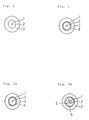
- Fig. 1 is a cross section of a conventional optical fiber comprising a core, a cladding and a resin coating layer,
- Fig. 2 is a cross section of a conventional hermetically coated optical fiber,
- Figs. 3A and 3B are cross sections of two embodiments of the hermetically coated optical fiber of the present invention, and
- Fig. 4 schematically shows an apparatus for producing the hermetically coated optical fiber according to the present invention.
- The present invention will be described by making reference to the accompanying drawings.
- Fig. 3A is a cross section of one embodiment of the hermetically coated optical fiber, which comprises a glass core 1, a
cladding 2 made of quartz glass doped with fluorine (F-doped SiO₂), aresin coating layer 3 and ahermetic coating 4 made of carbon. This embodiment has only onecladding 2. Alternatively, as shown in Fig. 3B, the optical fiber of the present invention additionally has asecond cladding 5. In the embodiment, thecladding 5 is doped with fluorine, while thecladding 2 may be or may not be doped with fluorine. When thecladding 2 is not doped, the core is doped with an additive which increases the refractive index of the core glass. - The carbon
hermetic layer 4 is preferably formed by a chemical vapor deposition of a hydrocarbon. Examples of the hydrocarbon are saturated hydrocarbons (e.g. methane, ethane, propane, etc.), unsaturated hydrocarbons (e.g. ethylene, propylene, acetylene, etc.), aromatic hydrocarbons (e.g. benzene, etc.) and their derivatives, particularly halogenated derivatives (e.g. carbon tetrachloride, chloroform, trichloroethylene, dichloroethylene, etc.) as well as mixtures of the hydrocarbons and their halogenated derivatives. Among them, the unsaturated hydrocarbons such as ethylene and acetylene are preferred. Also the aromatic hydrocarbons such as benzene are preferred. - Conditions for vapor depositing carbon are substantially the same as in the conventional method.
- One method for the production of the hermetically coated optical fiber will be explained with reference to an apparatus of Fig. 4. With a drawing device 20, a
bare glass fiber 11 is drawn from a preform 10 comprising a core and a cladding at least the outermost layer of which is doped with fluorine and introduced in acarbon coating device 30 with which a carbon coating is formed on the surface ofoptical fiber 11 to produce a carbon-coatedoptical fiber 12. Then, the carbon-coatedoptical fiber 12 passes through a device 40 for measuring a fiber diameter, acooling device 50 and aresin coating device 60 to produce a resin-coatedoptical fiber 13. The resin-coatedoptical fiber 13 is directly wound on a drum (not shown) through a capstan, or further jacketed with a resin coating such as Nylon and then wound on a drum. - The method of the present invention will be illustrated further in detail.
- The preform 10 is suspended in a
muffle tube 21 from an arm (not shown). Themuffle tube 21 is installed in afiber drawing furnace 22 which has aheater 23 for heating and melting a lower end portion of the preform 10. As the fiber drawing heater, any of known heaters such as an electric heater and a high-frequency heater can be used. Among the heaters, one which does not liberate the hydrogen molecules and/or dusts is preferred. With the drawing device 20, the bareoptical fiber 11 having substantially the same refractive index profile as that of the preform 10 can be produced and then introduced in thecarbon coating device 30. - The
carbon coating device 30 comprises areaction furnace 31, areaction tube 33 which is inserted in thefurnace 31 and acooling jacket 37 installed between thereaction furnace 31 and thereaction tube 37. Thereaction furnace 31 has anIR lamp 32 heat of which is concentrated to heat the bareoptical fiber 11 and an atmosphere surrounding theoptical fiber 11. With such concentrated heating, undesirable decomposition reactions other than on the surface of the bareoptical fiber 11 are prevented during coating the fiber with pyrolytic carbon. Thereaction tube 33 hasbranch tubes branch tubes 34b and 35b at the lower portion thereof. A sealing gas such as nitrogen gas is supplied through thebranch tubes 34b and 35b and exhausted through thebranch tubes reaction tube 33, three baffle plates withslits - The
cooling jacket 37 which is installed between thereaction tube 33 and thereaction furnace 31 has abranch tube 38 at its upper end and abranch tube 39 at its lower end. Through thebranch tubes reaction tube 33 is cooled from outside with the cooling jacket during carbon coating, not only excessive decomposition reaction is prevented but also the inner surface of thereaction tube 33 is not clouded with the decomposed products. In Fig. 4, "L" stands for a distance from a neck-down part of the preform 10 to the reaction tube interior containing the raw material. - The carbon coating has generally a thickness of 20 to 100 nm (200 to 1000 Å), preferably 30 to 60 nm (300 to 600Å).
- With the device 40 for measuring the fiber diameter which is provided just beneath the carbon-
coating device 30, an outer diameter of the carbon-coatedoptical fiber 12 is measured by means of laser light. With using the measured diameter of the optical fiber, the operation conditions are adjusted to keep the diameter of the bareoptical fiber 11 at a predetermined value. - With the
cooling device 50 which is positioned beneath the diameter measuring device 40, the carbon-coatedoptical fiber 12 is cooled to, for example, 70°C or lower. The cooling device 40 consists of, for example, a cylinder of 30 cm in length and 1.5 cm in inner diameter and through its interior, a cooling gas such as helium is flowed at, for example 10 liters per minute. - Beneath the
cooling device 50, theresin coating device 60 is installed. Thedevice 60 comprises adie 61 which is filled with a resin melt. While the carbon-coatedoptical fiber 12 is passed through thedie 61, it is coated with the resin to form the resin-coatedoptical fiber 13. - If excessive tension is applied to the optical fiber and the carbon film is formed on the stretched optical fiber, the carbon film tends to be broken when the tension is removed from the optical fiber. Therefore, the tension to be applied to the optical fiber during production should not exceed a certain limit. According to the experiments carried out by the present inventors, it has been found that the tension applied to the optical fiber should not exceed 20 MPa.
- The tension applied to the optical fiber can be easily controlled, for example, by adjusting the winding speed of the optical fiber or by adjusting the drawing temperature.
- In general, on the surface of quartz glass, hydroxyl (OH) groups tend to be present and bond with silicon atoms of the glass. When the carbon film is to be formed on such glass surface, carbon atoms may bond to the surface through the weak hydrogen bond but cannot be bond to the surface through the strong covalent bond. Therefore, the carbon film is partly broken or peeled off and microcrystals in the film damage the optical fiber glass, which reduces the strength of the optical fiber.
- In the present invention, since the outermost layer of the cladding contains fluorine, it may be assumed that the silicon atoms of the glass and the carbon atoms would directly bond each other through the covalent bond at higher probability. Thereby, the produced optical fiber has improved strength. That is, on the outermost layer of the F-doped SiO₂ cladding, a large number of F-Si- bonds may be present and react with the carbon-containing raw material so that the possibility of formation of strong C-Si bonds could be increased.
- For example, when the hydrocarbon is used as the raw material, the hydrogen and carbon atoms may react with the silicon atom as follows:

When the unsaturated hydrocarbon is used as the raw material, the reaction may proceed as follows:
whereby a more stable bond is formed and the C-Si bond becomes stronger. Therefore, the unsaturated hydrocarbons such as ethylene and acetylene are particularly preferred for forming the carbon coating according to the present invention. From the aromatic hydrocarbon such as benzene, the carbon film having similar properties to those of the carbon film made from the unsaturated hydrocarbon can be formed. - In the optical fiber which is hermetically coated with carbon, the hydrogen molecules do not migrate so that the reliability of the optical fiber is greatly increased.
- With the optical fiber comprising a core made of pure quartz (SiO₂), if the carbon film is broken and the hydrogen molecules penetrate into the core, the optical fiber is not influenced by the hydrogen molecules except the inherent light absorption of the hydrogen molecules. Further, the optical fiber comprising the core made of pure quartz has better radiation resistance.
- The present invention will be illustrated by following Examples.
- During drawing of an optical fiber having an outer diameter of 125 µm and comprising a cladding made of a glass of a composition shown in Table 1, a carbon film with a thickness of 500 Å was coated on the peripheral surface from a carbon-containing raw material shown in Table 1 by the CVD method.
- Among the raw materials, CH₄ and C₂H₂ were introduced as such to the reaction chamber since they are in the gas state at room temperature, and CCl₄ and C₆H₆ were introduced to the reaction chamber with a helium carrier gas by bubbling the carrier gas in them since they are in the liquid state at room temperature.
- The thickness of the carbon film was measured through Auger electron spectroscopy. Over the carbon film, a silicone resin was coated to produce a hermetically coated optical fiber having an outer diameter of 400 µm (Nos. 1 through 6). Then, the properties of each optical fiber were measured. The results are shown in Table 1.
- The uncoated optical fiber was a single mode optical fiber fabricated by the VAD method and had a core diameter of 10 µm and a cladding diameter of 125 µm, and the applied tension was 15 MPa during drawing and coating.
- To achieve the difference of the refractive index between the core and the cladding, a combination of a core glass of SiO₂ and a cladding glass of F-doped SiO₂ (F content: 1 % by weight), or a combination of a core glass of GeO₂-doped SiO₂ (GeO₂ content: 5 % by weight) and a cladding glass of SiO₂ was used. It was confirmed that, when no carbon film was present, the optical fiber comprising the SiO₂ core and one comprising the GeO₂-doped SiO₂ core had substantially the same properties with respect to the measured properties.
- The properties were measured as follows:
- A commercially available adhesive tape is wound around the optical fiber and peeled off. Then, a ratio of the peeled off area to the area which is covered by the adhesive tape is calculated and evaluated according to the following criteria:
- A: Very good (the ratio being zero)
- B: Good (the ratio being less than 0.1)
- C: Poor (the ratio being from 0.1 to 0.5)
- D: Bad (the ratio being larger than 0.5)
- One end of the optical fiber is fixed and the other end is pulled with measuring a load applied to the optical fiber, and the load at break is measured. The larger value means better strength.
- At pulling rates v₁ and v₂, the tensile test is carried out and tensile strength T₁ and T₂ are obtained. The dynamic fatigue parameter is defined by n which is calculated from the following equation:

The larger n means small fatigue of the glass, namely stress corrosion.
- As understood from the results of Table 1, the optical fibers comprising the cladding made of F-doped SiO₂ glass and having the carbon film synthesized from the hydrocarbon (Nos. 1, 5 and 7) had better dynamic fatigue parameters, adhesivity of the carbon film and initial strength.
- Around a single mode optical fiber having a core diameter of 5 µm and a cladding diameter of 125 µm which was fabricated by the VAD method from the combination of glasses shown in Table 2 which achieved the refractive index difference of 0.7 %, a carbon film was coated from C₂H₂ under the same conditions as in Example 1 but keeping the tension on the optical fiber at 5 MPa and then the resin was coated to produce a coated optical fiber (Nos. A, B and C).
- The properties of the optical fibers were measured as in Example 1. The results are shown in Table 2. In particular, the optical fiber No. C of the present invention had very good properties such as the initial strength of 5.5 kg and the dynamic fatigue parameter of larger than 100.

- Around a single mode optical fiber having a core diameter of 10 µm and a cladding diameter of 125 µm which was fabricated by the VAD method from the combination of the core glass of GeO₂-doped SiO₂ (GeO₂ content: 5 % by weight) and the cladding glass of SiO₂ which achieved the refractive index difference of 0.3 %, a carbon film was coated from C₂H₂ under the same conditions as in Example 1 but keeping the tension on the optical fiber at 20 MPa and then the resin was coated to produce a coated optical fiber (No. D for comparison).
- Around the optical fiber of the above, a second cladding was formed from F-doped SiO₂ (F content: 3 % by weight) by the plasma outer deposition method to a thickness of 2 to 3 µm. Then, the carbon film and the resin were coated in the same manner as above.
- The properties of the optical fiber Nos. D and E were measured as in Example 1. The results are shown in Table 3.

- Around a single mode optical fiber having a core diameter of 10 µm and a cladding diameter of 125 µm which was fabricated by the VAD method from the combination of glasses shown in Table 4 which achieved the refractive index difference of 0.3 %, a carbon film was coated from C₂H₄ under the same conditions as in Example 1 but keeping the tension on the optical fiber at the value shown in Table 4 and then the resin was coated to produce a coated optical fiber (Nos. F, G and H).
- The properties of the optical fibers were measured as in Example 1. The results are shown in Table 4.
- As understood from the results of Table 4, the optical fibers coated with the carbon film under tension of less than 20 MPa had very good properties, while the optical fiber coated with the carbon film under tension of 25 MPa had poor properties such as the initial strength of 4 kg.

Claims (8)
- A hermetically coated optical fiber which comprises a core made of glass, a cladding made of quartz glass surrounding the core, the outermost layer of which contains fluorine, and a hermetic carbon layer surrounding the fluorine-containing glass layer.
- A hermetically coated optical fiber according to claim 1, wherein the core is made of SiO₂.
- A hermetically coated optical fiber according to claim 1, wherein the cladding comprises at least two layers, the outermost of which contains fluorine.
- A method for producing a hermetically coated optical fiber which comprises:(i) drawing a preform under a tension of not larger than 20 MPa to form an optical fiber comprising a core made of glass, and a cladding made of quartz glass surrounding the core, the outermost layer of which contains fluorine; and(ii) hermetically coating a carbon film around the drawn optical fiber.
- A method according to claim 4, wherein the carbon film is formed by chemical vapor deposition.
- A method according to claim 5, wherein the carbon film is formed from a hydrocarbon by chemical vapor deposition.
- A method according to claim 6, wherein the hydrocarbon is an unsaturated hydrocarbon.
- A method according to claim 7, wherein the unsaturated hydrocarbon is ethylene or acetylene.
Applications Claiming Priority (2)
| Application Number | Priority Date | Filing Date | Title |
|---|---|---|---|
| JP180156/89 | 1989-06-13 | ||
| JP18015689 | 1989-07-13 |
Publications (2)
| Publication Number | Publication Date |
|---|---|
| EP0402895A1 EP0402895A1 (en) | 1990-12-19 |
| EP0402895B1 true EP0402895B1 (en) | 1993-12-15 |
Family
ID=16078377
Family Applications (1)
| Application Number | Title | Priority Date | Filing Date |
|---|---|---|---|
| EP90111193A Expired - Lifetime EP0402895B1 (en) | 1989-06-13 | 1990-06-13 | Hermetically coated optical fiber and production of the same |
Country Status (6)
| Country | Link |
|---|---|
| US (1) | US5157755A (en) |
| EP (1) | EP0402895B1 (en) |
| JP (1) | JP2975642B2 (en) |
| KR (1) | KR970000903B1 (en) |
| AU (1) | AU629648B2 (en) |
| DE (1) | DE69005203T2 (en) |
Families Citing this family (19)
| Publication number | Priority date | Publication date | Assignee | Title |
|---|---|---|---|---|
| NO920574L (en) * | 1991-02-14 | 1992-08-17 | Sumitomo Electric Industries | METHOD AND APPARATUS FOR MANUFACTURING COATED OPTICAL FIBERS |
| US5346520A (en) * | 1992-09-23 | 1994-09-13 | Corning Incorporated | Apparatus for applying a carbon coating to optical fibers |
| FR2708754B1 (en) * | 1993-08-04 | 1995-09-08 | Alcatel Cable | Fiber optic cable and associated production method. |
| US5664041A (en) * | 1993-12-07 | 1997-09-02 | Dsm Desotech, Inc. | Coating system for glass adhesion retention |
| JPH07261048A (en) * | 1994-03-23 | 1995-10-13 | Sumitomo Electric Ind Ltd | Dispersion compensating fiber |
| US5966490A (en) * | 1997-03-21 | 1999-10-12 | Sdl, Inc. | Clad optic fiber, and process for production thereof |
| US6701054B1 (en) | 1997-06-23 | 2004-03-02 | Corning Incorporated | Thin carbon coating of optical waveguides |
| WO1998059268A1 (en) * | 1997-06-23 | 1998-12-30 | Corning Incorporated | Thin carbon coating of optical waveguides |
| EP0908748A1 (en) * | 1997-10-07 | 1999-04-14 | N.V. Bekaert S.A. | Communication cable with improved tensile member |
| CA2323481C (en) * | 1998-03-12 | 2005-01-11 | Tomoegawa Paper Co., Ltd. | Optical connection component and method of producing the same |
| US6325981B1 (en) | 1999-09-28 | 2001-12-04 | Alcatel | Apparatus and method for curing a photocurable coating provided on a fiber |
| DE10136387A1 (en) * | 2001-07-26 | 2003-02-13 | Zeiss Carl | Optical objective for semiconductor lithography has optical element with reflective reference surface used for adjustment relative to objective |
| FR2840690B1 (en) * | 2002-06-06 | 2004-08-27 | Cit Alcatel | FIBER OPTIC CABLE COMPRISING A HYDROGEN ABSORBING COMPOSITION |
| KR101213552B1 (en) | 2004-04-09 | 2012-12-18 | 엔티엔 가부시키가이샤 | Dynamic pressure bearing device |
| US7257301B2 (en) * | 2005-03-31 | 2007-08-14 | Baker Hughes Incorporated | Optical fiber |
| EP2138471A1 (en) * | 2008-06-25 | 2009-12-30 | Acreo AB | Atomic layer deposition of hydrogen barrier coatings on optical fibers |
| US8724951B2 (en) * | 2010-01-26 | 2014-05-13 | Corning Incorporated | Optical fiber |
| US20110300367A1 (en) * | 2010-06-07 | 2011-12-08 | Ching-Kee Chien | Optical Fiber With Photoacid Coating |
| EP4291931A1 (en) * | 2021-02-12 | 2023-12-20 | OFS Fitel, LLC | Systems and methods for enhanced back scattering in optical fibers with hermeticity |
Family Cites Families (11)
| Publication number | Priority date | Publication date | Assignee | Title |
|---|---|---|---|---|
| US4183621A (en) * | 1977-12-29 | 1980-01-15 | International Telephone And Telegraph Corporation | Water resistant high strength fibers |
| US4319803A (en) * | 1978-11-24 | 1982-03-16 | Hewlett-Packard Company | Optical fiber coating |
| US4435040A (en) * | 1981-09-03 | 1984-03-06 | Bell Telephone Laboratories, Incorporated | Double-clad optical fiberguide |
| US4512629A (en) * | 1982-03-30 | 1985-04-23 | Hewlett-Packard Company | Optical fiber with hermetic seal and method for making same |
| GB8401089D0 (en) * | 1984-01-16 | 1984-02-15 | Gen Electric Co Plc | Coating optical fibres |
| DE3500672A1 (en) * | 1985-01-11 | 1986-07-17 | Philips Patentverwaltung | LIGHT-GUIDE FIBER WITH FLUOROUS DOPING AND METHOD FOR THE PRODUCTION THEREOF |
| US4874222A (en) * | 1986-03-31 | 1989-10-17 | Spectran Corporation | Hermetic coatings for non-silica based optical fibers |
| KR900003449B1 (en) * | 1986-06-11 | 1990-05-19 | 스미도모덴기고오교오 가부시기가이샤 | Dispersion-shift fiber and its production |
| EP0308143B1 (en) * | 1987-09-18 | 1993-11-24 | AT&T Corp. | Hermetically sealed optical fibers |
| US4838643A (en) * | 1988-03-23 | 1989-06-13 | Alcatel Na, Inc. | Single mode bend insensitive fiber for use in fiber optic guidance applications |
| AU624203B2 (en) * | 1988-12-21 | 1992-06-04 | Sumitomo Electric Industries, Ltd. | Method and apparatus for producing coated optical fiber |
-
1990
- 1990-06-12 JP JP2151510A patent/JP2975642B2/en not_active Expired - Lifetime
- 1990-06-12 AU AU56955/90A patent/AU629648B2/en not_active Ceased
- 1990-06-12 KR KR1019900008573A patent/KR970000903B1/en not_active IP Right Cessation
- 1990-06-13 DE DE90111193T patent/DE69005203T2/en not_active Expired - Fee Related
- 1990-06-13 EP EP90111193A patent/EP0402895B1/en not_active Expired - Lifetime
-
1991
- 1991-10-15 US US07/774,167 patent/US5157755A/en not_active Expired - Lifetime
Non-Patent Citations (1)
| Title |
|---|
| PATENT ABSTRACTS OF JAPAN vol. 13, no. 175 (P-863)(3523), 25 April 1989. * |
Also Published As
| Publication number | Publication date |
|---|---|
| AU5695590A (en) | 1990-12-20 |
| DE69005203T2 (en) | 1994-05-11 |
| DE69005203D1 (en) | 1994-01-27 |
| EP0402895A1 (en) | 1990-12-19 |
| KR970000903B1 (en) | 1997-01-21 |
| KR910000556A (en) | 1991-01-29 |
| US5157755A (en) | 1992-10-20 |
| AU629648B2 (en) | 1992-10-08 |
| JPH0394210A (en) | 1991-04-19 |
| JP2975642B2 (en) | 1999-11-10 |
Similar Documents
| Publication | Publication Date | Title |
|---|---|---|
| EP0402895B1 (en) | Hermetically coated optical fiber and production of the same | |
| EP0374926B1 (en) | Method for producing a carbon-coated optical fiber | |
| US5000541A (en) | Hermetically sealed optical fibers | |
| EP0308143B1 (en) | Hermetically sealed optical fibers | |
| EP0353934B1 (en) | Method of producing an optical fibre | |
| EP0472944B1 (en) | Method and apparatus for producing hermetic coated optical fiber | |
| US5235666A (en) | Production of a hermetically coated optical fiber | |
| JPH0380134A (en) | Carbon coating of optical fiber | |
| JPH0227308A (en) | Optical fiber and its production | |
| JP2727702B2 (en) | Manufacturing method of carbon coated optical fiber | |
| JP2966883B2 (en) | Method of manufacturing optical fiber having hermetic coating | |
| JP2683070B2 (en) | Optical fiber manufacturing method | |
| JP2644018B2 (en) | Optical fiber manufacturing method | |
| JP2955787B2 (en) | Manufacturing method of silica glass optical fiber | |
| JPH06345494A (en) | Carbon-coated optical fiber | |
| JP2825843B2 (en) | Optical fiber | |
| JP2710402B2 (en) | Optical fiber | |
| JP3039948B2 (en) | Optical fiber manufacturing method | |
| JP3039961B2 (en) | Optical fiber manufacturing method | |
| JP3039949B2 (en) | Optical fiber manufacturing method | |
| JPH0442839A (en) | Production of optical fiber | |
| JP2595364B2 (en) | Optical fiber manufacturing method | |
| JP2683147B2 (en) | Optical fiber manufacturing method | |
| JPH04285041A (en) | Production of hermetically coated optical fiber | |
| JPH02243539A (en) | Production of carbon-coated optical fiber |
Legal Events
| Date | Code | Title | Description |
|---|---|---|---|
| PUAI | Public reference made under article 153(3) epc to a published international application that has entered the european phase |
Free format text: ORIGINAL CODE: 0009012 |
|
| AK | Designated contracting states |
Kind code of ref document: A1 Designated state(s): DE FR GB |
|
| 17P | Request for examination filed |
Effective date: 19901220 |
|
| 17Q | First examination report despatched |
Effective date: 19920610 |
|
| GRAA | (expected) grant |
Free format text: ORIGINAL CODE: 0009210 |
|
| AK | Designated contracting states |
Kind code of ref document: B1 Designated state(s): DE FR GB |
|
| REF | Corresponds to: |
Ref document number: 69005203 Country of ref document: DE Date of ref document: 19940127 |
|
| ET | Fr: translation filed | ||
| PLBE | No opposition filed within time limit |
Free format text: ORIGINAL CODE: 0009261 |
|
| STAA | Information on the status of an ep patent application or granted ep patent |
Free format text: STATUS: NO OPPOSITION FILED WITHIN TIME LIMIT |
|
| 26N | No opposition filed | ||
| REG | Reference to a national code |
Ref country code: GB Ref legal event code: IF02 |
|
| PGFP | Annual fee paid to national office [announced via postgrant information from national office to epo] |
Ref country code: GB Payment date: 20050608 Year of fee payment: 16 |
|
| PGFP | Annual fee paid to national office [announced via postgrant information from national office to epo] |
Ref country code: DE Payment date: 20050609 Year of fee payment: 16 |
|
| PG25 | Lapsed in a contracting state [announced via postgrant information from national office to epo] |
Ref country code: GB Free format text: LAPSE BECAUSE OF NON-PAYMENT OF DUE FEES Effective date: 20060613 |
|
| PG25 | Lapsed in a contracting state [announced via postgrant information from national office to epo] |
Ref country code: DE Free format text: LAPSE BECAUSE OF NON-PAYMENT OF DUE FEES Effective date: 20070103 |
|
| GBPC | Gb: european patent ceased through non-payment of renewal fee |
Effective date: 20060613 |
|
| PGFP | Annual fee paid to national office [announced via postgrant information from national office to epo] |
Ref country code: FR Payment date: 20080617 Year of fee payment: 19 |
|
| REG | Reference to a national code |
Ref country code: FR Ref legal event code: ST Effective date: 20100226 |
|
| PG25 | Lapsed in a contracting state [announced via postgrant information from national office to epo] |
Ref country code: FR Free format text: LAPSE BECAUSE OF NON-PAYMENT OF DUE FEES Effective date: 20090630 |