EP0402309A1 - Profiled rod made from compact composite and method for producing same - Google Patents
Profiled rod made from compact composite and method for producing same Download PDFInfo
- Publication number
- EP0402309A1 EP0402309A1 EP90810364A EP90810364A EP0402309A1 EP 0402309 A1 EP0402309 A1 EP 0402309A1 EP 90810364 A EP90810364 A EP 90810364A EP 90810364 A EP90810364 A EP 90810364A EP 0402309 A1 EP0402309 A1 EP 0402309A1
- Authority
- EP
- European Patent Office
- Prior art keywords
- profile
- core
- bar according
- matrix
- fibers
- Prior art date
- Legal status (The legal status is an assumption and is not a legal conclusion. Google has not performed a legal analysis and makes no representation as to the accuracy of the status listed.)
- Granted
Links
Images


Classifications
-
- D—TEXTILES; PAPER
- D04—BRAIDING; LACE-MAKING; KNITTING; TRIMMINGS; NON-WOVEN FABRICS
- D04C—BRAIDING OR MANUFACTURE OF LACE, INCLUDING BOBBIN-NET OR CARBONISED LACE; BRAIDING MACHINES; BRAID; LACE
- D04C1/00—Braid or lace, e.g. pillow-lace; Processes for the manufacture thereof
- D04C1/02—Braid or lace, e.g. pillow-lace; Processes for the manufacture thereof made from particular materials
-
- B—PERFORMING OPERATIONS; TRANSPORTING
- B29—WORKING OF PLASTICS; WORKING OF SUBSTANCES IN A PLASTIC STATE IN GENERAL
- B29C—SHAPING OR JOINING OF PLASTICS; SHAPING OF MATERIAL IN A PLASTIC STATE, NOT OTHERWISE PROVIDED FOR; AFTER-TREATMENT OF THE SHAPED PRODUCTS, e.g. REPAIRING
- B29C70/00—Shaping composites, i.e. plastics material comprising reinforcements, fillers or preformed parts, e.g. inserts
- B29C70/04—Shaping composites, i.e. plastics material comprising reinforcements, fillers or preformed parts, e.g. inserts comprising reinforcements only, e.g. self-reinforcing plastics
- B29C70/06—Fibrous reinforcements only
- B29C70/08—Fibrous reinforcements only comprising combinations of different forms of fibrous reinforcements incorporated in matrix material, forming one or more layers, and with or without non-reinforced layers
- B29C70/083—Combinations of continuous fibres or fibrous profiled structures oriented in one direction and reinforcements forming a two dimensional structure, e.g. mats
- B29C70/085—Combinations of continuous fibres or fibrous profiled structures oriented in one direction and reinforcements forming a two dimensional structure, e.g. mats the structure being deformed in a three dimensional configuration
-
- B—PERFORMING OPERATIONS; TRANSPORTING
- B29—WORKING OF PLASTICS; WORKING OF SUBSTANCES IN A PLASTIC STATE IN GENERAL
- B29C—SHAPING OR JOINING OF PLASTICS; SHAPING OF MATERIAL IN A PLASTIC STATE, NOT OTHERWISE PROVIDED FOR; AFTER-TREATMENT OF THE SHAPED PRODUCTS, e.g. REPAIRING
- B29C70/00—Shaping composites, i.e. plastics material comprising reinforcements, fillers or preformed parts, e.g. inserts
- B29C70/04—Shaping composites, i.e. plastics material comprising reinforcements, fillers or preformed parts, e.g. inserts comprising reinforcements only, e.g. self-reinforcing plastics
- B29C70/28—Shaping operations therefor
- B29C70/40—Shaping or impregnating by compression not applied
- B29C70/50—Shaping or impregnating by compression not applied for producing articles of indefinite length, e.g. prepregs, sheet moulding compounds [SMC] or cross moulding compounds [XMC]
- B29C70/52—Pultrusion, i.e. forming and compressing by continuously pulling through a die
- B29C70/525—Component parts, details or accessories; Auxiliary operations
-
- B—PERFORMING OPERATIONS; TRANSPORTING
- B29—WORKING OF PLASTICS; WORKING OF SUBSTANCES IN A PLASTIC STATE IN GENERAL
- B29D—PRODUCING PARTICULAR ARTICLES FROM PLASTICS OR FROM SUBSTANCES IN A PLASTIC STATE
- B29D99/00—Subject matter not provided for in other groups of this subclass
- B29D99/0003—Producing profiled members, e.g. beams
-
- B—PERFORMING OPERATIONS; TRANSPORTING
- B29—WORKING OF PLASTICS; WORKING OF SUBSTANCES IN A PLASTIC STATE IN GENERAL
- B29D—PRODUCING PARTICULAR ARTICLES FROM PLASTICS OR FROM SUBSTANCES IN A PLASTIC STATE
- B29D99/00—Subject matter not provided for in other groups of this subclass
- B29D99/0046—Producing rods
-
- B—PERFORMING OPERATIONS; TRANSPORTING
- B29—WORKING OF PLASTICS; WORKING OF SUBSTANCES IN A PLASTIC STATE IN GENERAL
- B29K—INDEXING SCHEME ASSOCIATED WITH SUBCLASSES B29B, B29C OR B29D, RELATING TO MOULDING MATERIALS OR TO MATERIALS FOR MOULDS, REINFORCEMENTS, FILLERS OR PREFORMED PARTS, e.g. INSERTS
- B29K2101/00—Use of unspecified macromolecular compounds as moulding material
- B29K2101/12—Thermoplastic materials
-
- B—PERFORMING OPERATIONS; TRANSPORTING
- B29—WORKING OF PLASTICS; WORKING OF SUBSTANCES IN A PLASTIC STATE IN GENERAL
- B29L—INDEXING SCHEME ASSOCIATED WITH SUBCLASS B29C, RELATING TO PARTICULAR ARTICLES
- B29L2031/00—Other particular articles
- B29L2031/06—Rods, e.g. connecting rods, rails, stakes
Definitions
- the invention relates to a profile rod made of compact composite material and profile pieces made therefrom and a method for their production.
- profile bars are e.g. known in the form of fiber-reinforced thermosets such as epoxies and polyester with reinforcements made of glass or carbon fibers.
- these known profiles are either still mechanically weak, such as glass mat-polyester profiles, or they are very complex and correspondingly expensive to manufacture, e.g. wound carbon fiber epoxy tubes. They are also not deformable and are only manufactured for a precisely defined, relatively narrowly limited application. Above all, connections and connections with such profiles are difficult and expensive to manufacture.
- the object of the present invention is to provide high-strength profiles in a simple and inexpensive manner, which can be used very universally. Above all, they should be formable and enable connections to other parts to be made in a simple manner and with as little loss of strength as possible, and also to be adaptable to existing connecting elements. In addition, they should have high mechanical strengths, especially torsional and shear strengths, as well as a wear-resistant surface. This is the case with the inventive Profile bars solved in that the composite material consists of technical continuous fibers in a thermoplastic matrix and that it has an inner core with unidirectional fibers and at least one sheath enveloping the core with a braided fiber tube.
- thermoplastic matrix and the structure according to the invention make it possible to deform the profile rods or cut profile pieces in a wide variety of ways without losing their compactness and the good mechanical properties, for example bending them or pressing them flat at the ends. Eyes, for example for screw connections or the insertion of bolts, can also be subsequently molded in thermoplastic, without material having to be removed, and thus without significant weakening of the profile at the sensitive connection point. Welding with other profile pieces or with compatible foreign parts is also possible.
- thermoplastic polymers such as PEEK, PPS, PES, PEI, PA, PP, PC or PS can be used as a matrix, which can be processed easily and without high temperatures.
- Light, inorganic matrix materials such as glass, aluminum or titanium can also be used.
- Carbon, aramid, glass or boron fibers are particularly suitable as high-strength and light reinforcing fibers. Good combinations result from PEEK or PPS with at least 45 volume percent of carbon, aramid or glass fibers.
- a cross-sectional area of the sheathing which is at least 15% of the cross-sectional area of the UD core
- high tensile and compressive strengths as well as good torsional and shear strengths can be achieved.
- enveloping sheath braids can be produced particularly torsion-resistant and also flexible profile bars.
- the mechanical properties can be further adapted and optimized through different fiber angles in the individual sheathing layers.
- further unidirectional fabrics can also be inserted between the cladding layers.
- the unidirectional core can be slightly twisted to facilitate length compensation on bends.
- the profile bars can be designed in cross sections of various shapes for a large number of areas of application.
- Profile pieces are formed from the profile rod according to the invention by reshaping or bending in at least one partial area. This enables a large number of high-strength components to be produced in a simple manner, such as levers, connecting rods or springs. These profile pieces can have flats, molded eyes or welds with other parts.
- the method for producing the profiled bars according to the invention is that the unidirectional core and the covering braids are first heated and then continuously formed together in one operation in a pultrusion device, whereby they are compactly consolidated under pressure and partial cooling and pressed into the specified profile shape, whereby Preheating, feed, tensile forces, cooling rate, shaping and forming section in the pultrusion device are matched to the matrix and fibers in such a way that the consolidation takes place under optimal pressure.
- This process is particularly simple and efficient.
- FIG. 1 shows in section an inventive compact, light profile rod 10 with a thermoplastic matrix, an inner core 1 with unidirectional, high-strength technical continuous fibers and an enveloping outer jacket layer 6 made of a braided fiber tube.
- the cross-sectional area 12 of the cladding layer is preferably at least 15% of that (11) of the UD core.
- the braid jacket 6 also results in a strong cohesion of the UD core and good wear properties, since no individual fibers can sprout on the surface.
- the fiber angle W of the sheath braid to the longitudinal axis 13 from here, for example, approximately 45 °. Thanks to this fiber arrangement and the thermoplastic matrix, the profile bars can be easily thermoplastic deformed and bent for a wide variety of applications. Only the matrix is deformed, while the length of the high-strength fibers necessarily remains constant. Changes in shape are only possible by arranging the fibers in the matrix or changing them. A deformation, for example from a circular cross section with the circumference U1 to an elliptical shape with a larger circumference U2 in FIG. 3, can take place with a constant cross-sectional area F in that the fiber angle W changes accordingly, that is to say W2 becomes larger than W1.
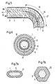
- a length compensation for thermoplastic bending of the profile bar are made possible (Fig. 2, 5).
- a length compensation of the core fibers can also take place without a twisted core 1, as is shown, for example, in FIG. 8 by the cross-sectional planes 31, 32, 33 with the same fiber length.
- Fig. 4 shows a profile bar with several superimposed sheath braid layers 6, 7, 8.
- the individual sheath layers can have different fiber angles W, e.g. between 30 and 60 °, in order to optimize the desired torsional strength and bending properties.
- Fig. 5 two sheath braids 6 and 7 are shown with increasing fiber angle W outwards.
- the fiber angle W3 of e.g. 50 ° is larger than W4 with e.g. 40 °. In the area of the bend 15, this facilitates the compensation of the different lengths of the outer and inner bend.
- the length compensation in the UD core 1 is achieved here by a slight torsion 27 of the UD fibers.
- UD longitudinal fibers shows additional further UD cladding layers 2 and 3 between the outer cladding braids 6, 7, 8, which can also be twisted slightly.
- the proportion of UD longitudinal fibers, the number, arrangement and thickness of the different layers are combined in accordance with the desired requirement profile. Long tensile and compressive strengths are achieved with UD longitudinal fibers, braided sheaths with optimized fiber angles result in high torsional and shear strengths.
- FIG. 7 a to f show various possible cross-sectional shapes of the profile bars according to the invention: with a flattened oval shape 21, rounded triangle 24, rectangle 23 and polygon 22 and also with concave cross sections such as L and T shapes 25 and 26.
- profiles can be made in one Operation can be continuously manufactured, e.g. first formed into a flat rectangle 23 and immediately afterwards formed into an L-shape 25 or first into a triangular shape 24 into a T-shape 26, which in the two partial areas 51, 52 of FIG. 11, and O1, O2 of Fig. 12 is executed.
- profile pieces of various shapes can be produced in the simplest possible way. Any components such as levers, springs, tension rods, etc. can be created by simply cutting, bending, shaping and connecting. This is not possible with high-strength metal profiles or with previous thermoset composite profiles.
- a spiral spring part 57 consists of two double arches 37, 38, each of which was produced by thermoplastic deformation of the entire double arch from a round profile with a non-twisted UD core 1.
- the length compensation in the core 1 takes place in the thermoplastic matrix, 31, 32, 33 representing cross-sectional planes of the same fiber length.
- a flattening 41 with a molded-in eye 42 is produced thermoplastic.
- the profile piece 57 is screwed to a holder and a support 39 is supported in the middle.
- Fig. 9 shows a connection end with a flat 41, eye 42 and an additional thermoplastic reinforcement 43 made of profile material.
- a spring 44 in FIG. 10 is welded 46 to a holder.
- FIG. 11 shows a pultrusion device 47 for producing profile bars 10 according to the invention, which are pulled out of the device 47 by a tensile force Z1 with the feed speed V.
- a tensile force Z1 with the feed speed V.
- the necessary temperature T1 is generated by a heating source 48.
- the necessary pressure P1 is built up in the inlet area 49.
- the shaping and consolidation area O is used for the shaping and consolidation of the profile rod, which is subsequently cooled in the cooling area A, still under pressure P1, to a temperature T2 at which no further plastic deformation occurs.
- the method according to the invention is further explained on the basis of the temperature and pressure profiles of FIG. 12 corresponding to the pultrusion device 47.
- the heating area H the starting material is brought to the necessary forming temperature T1.
- the pressure build-up on P1 takes place in area D, followed by the forming area O, O1, O2.
- the pressure P1 is still cooled to the fixed temperature T2.
- the finished profile rod 10 then drops in pressure and is cooled further.
- the areas H, D, O1, O2, A of FIG. 12 correspond to the device parts 48, 49, 51, 52, 56 in FIG. 11.
- Fibers, fiber arrangement and a desired profile shape with sufficient forming distance L are the parameters heating rate H, tensile forces Z1, Z2, Z3 and cooling rate set that an optimal feed speed V is achieved with the necessary course of T and P according to FIG. 12. This also depends on the type of raw material.
- surface-treated fibers can be used as UD rovings or fiber braid sleeves mixed with thermoplastic threads, mixed fibers (hybrid yarn), rovings in thermoplastic hoses or even pre-impregnated rovings.
- Non-impregnated fibers require higher pressures P1 than prepreg materials.
Abstract
Description
Die Erfindung betrifft eine Profilstange aus kompaktem Verbundwerkstoff und daraus gefertigte Profilstücke und ein Verfahren zu deren Herstellung. Solche Profilstangen sind z.B. in Form von faserverstärkten Duroplasten wie Epoxide und Polyester mit Verstärkungen aus Glas- oder Kohlefasern bekannt. Diese bekannten Profile sind jedoch entweder mechanisch noch relativ schwach wie beispielsweise Glasmatten-Polyester-Profile oder sie sind sehr aufwendig und entsprechend teuer herzustellen, wie z.B. gewickelte Kohlefaserepoxyrohre. Sie sind auch nicht verformbar und nur für eine genau definierte, relativ eng begrenzte Anwendung hergestellt. Vor allem Anschlüsse und Verbindungen mit solchen Profilen sind schwer und aufwendig herzustellen.The invention relates to a profile rod made of compact composite material and profile pieces made therefrom and a method for their production. Such profile bars are e.g. known in the form of fiber-reinforced thermosets such as epoxies and polyester with reinforcements made of glass or carbon fibers. However, these known profiles are either still mechanically weak, such as glass mat-polyester profiles, or they are very complex and correspondingly expensive to manufacture, e.g. wound carbon fiber epoxy tubes. They are also not deformable and are only manufactured for a precisely defined, relatively narrowly limited application. Above all, connections and connections with such profiles are difficult and expensive to manufacture.
Aufgabe der vorliegenden Erfindung ist es nun, auf einfache und kostengünstige Art hochfeste Profile zu schaffen, welche sehr universell einsetzbar sind. Sie sollen vor allem umformbar sein und auf einfache Art und mit möglichst geringem Festigkeitsverlust Verbindungen mit anderen Teilen ermöglichen wie auch an bestehende Verbindungselemente angepasst werden können. Zudem sollen sie hohe mechanische Festigkeiten, speziell Torsions- und Schubfestigkeiten wie auch eine verschleissfeste Oberfläche aufweisen. Dies wird bei den erfindungsgemässen Profilstangen dadurch gelöst, dass der Verbundwerkstoff aus technischen Endlosfasern in einer thermoplastischen Matrix besteht, und dass er einen inneren Kern mit unidirektionalen Fasern und mindestens einen den Kern umhüllenden Mantel mit einem geflochtenen Faserschlauch aufweist. Durch die thermoplastische Matrix und den erfindungsgemässen Aufbau ist es möglich, die Profilstangen, bzw. zugeschnittene Profilstücke, auf verschiedenste Arten zu verformen, ohne dass deren Kompaktheit und die guten mechanischen Eigenschaften verloren gehen, beispielsweise zu biegen oder an den Enden flach zu drücken. Auch Augen, z.B. für Verschraubungen oder die Aufnahme von Bolzen können nachträglich thermoplastisch eingeformt werden, ohne dass Material abgetragen werden muss, und damit ohne wesentliche Schwächung des Profils an der empfindlichen Verbindungsstelle. Auch eine Verschweissung mit anderen Profilstücken oder mit kompatiblen Fremdteilen ist möglich.The object of the present invention is to provide high-strength profiles in a simple and inexpensive manner, which can be used very universally. Above all, they should be formable and enable connections to other parts to be made in a simple manner and with as little loss of strength as possible, and also to be adaptable to existing connecting elements. In addition, they should have high mechanical strengths, especially torsional and shear strengths, as well as a wear-resistant surface. This is the case with the inventive Profile bars solved in that the composite material consists of technical continuous fibers in a thermoplastic matrix and that it has an inner core with unidirectional fibers and at least one sheath enveloping the core with a braided fiber tube. The thermoplastic matrix and the structure according to the invention make it possible to deform the profile rods or cut profile pieces in a wide variety of ways without losing their compactness and the good mechanical properties, for example bending them or pressing them flat at the ends. Eyes, for example for screw connections or the insertion of bolts, can also be subsequently molded in thermoplastic, without material having to be removed, and thus without significant weakening of the profile at the sensitive connection point. Welding with other profile pieces or with compatible foreign parts is also possible.
Die abhängigen Ansprüche betreffen besonders vorteilhafte Ausführungen der Erfindung. Danach können thermoplastische Polymere wie PEEK, PPS, PES, PEI, PA, PP, PC oder PS als Matrix eingesetzt werden, welche einfach und ohne hohe Temperaturen verarbeitbar sind. Es können auch leichte, anorganische Matrixmaterialien wie Glas, Aluminium oder Titan eingesetzt werden. Als hochfeste und leichte Verstärkungsfasern können sich besonders gut Kohle, Aramid, Glas oder Borfasern eignen. Gute Kombinationen ergeben sich aus PEEK oder PPS mit mindestens 45 Volumen-Prozent an Kohle, Aramid oder Glasfasern. Mit einer Querschnittsfläche der Ummantelung, welche mindestens 15 % der Querschnittsfläche des UD-Kerns beträgt, können sowohl hohe Zug- und Druckfestigkeiten als auch gute Torsions- und Schubfestigkeiten erreicht werden. Mit mehreren übereinanderliegenden, umhüllenden Mantelgeflechten können besonders torsionsfeste und auch biegefähige Profilstangen erzeugt werden. Durch unterschiedliche Faserwinkel in den einzelnen Ummantelungsschichten können die mechanischen Eigenschaften weiter angepasst und optimiert werden. Für dicke Profilstangen können zwischen den Mantelschichten auch weitere unidirektionale Gelege eingeschoben sein. Der unidirektionale Kern kann leicht tordiert sein zur Erleichterung eines Längenausgleichs bei Biegungen. Die Profilstangen können in Querschnitten verschiedenster Form für eine Grosszahl von Einsatzbereichen ausgebildet sein. Profilstücke werden aus der erfindungsgemässen Profilstange gebildet durch Umformung oder Biegung in mindestens einem Teilbereich. Dadurch kann auf einfache Art eine Vielzahl von hochfesten Bauelementen erzeugt werden wie Hebel, Verbindungsstangen oder Federn. Diese Profilstücke können Abflachungen, eingeformte Augen oder auch Verschweissungen mit anderen Teilen aufweisen.The dependent claims relate to particularly advantageous embodiments of the invention. Thereafter, thermoplastic polymers such as PEEK, PPS, PES, PEI, PA, PP, PC or PS can be used as a matrix, which can be processed easily and without high temperatures. Light, inorganic matrix materials such as glass, aluminum or titanium can also be used. Carbon, aramid, glass or boron fibers are particularly suitable as high-strength and light reinforcing fibers. Good combinations result from PEEK or PPS with at least 45 volume percent of carbon, aramid or glass fibers. With a cross-sectional area of the sheathing, which is at least 15% of the cross-sectional area of the UD core, high tensile and compressive strengths as well as good torsional and shear strengths can be achieved. With Several superimposed, enveloping sheath braids can be produced particularly torsion-resistant and also flexible profile bars. The mechanical properties can be further adapted and optimized through different fiber angles in the individual sheathing layers. For thick profile bars, further unidirectional fabrics can also be inserted between the cladding layers. The unidirectional core can be slightly twisted to facilitate length compensation on bends. The profile bars can be designed in cross sections of various shapes for a large number of areas of application. Profile pieces are formed from the profile rod according to the invention by reshaping or bending in at least one partial area. This enables a large number of high-strength components to be produced in a simple manner, such as levers, connecting rods or springs. These profile pieces can have flats, molded eyes or welds with other parts.
Das Verfahren zur Herstellung der erfindungsgemässen Profilstangen besteht darin, dass der unidirektionale Kern und die Ummantelungsgeflechte zuerst aufgeheizt und dann zusammen in einem Arbeitsgang in einer Pultrusionseinrichtung kontinuierlich gebildet werden, wobei sie unter Druck und teilweiser Abkühlung kompakt konsolidiert und in die vorgegebene Profilform gepresst werden, wobei Vorheizung, Vorschub, Zugkräfte, Abkühlrate, Formgebung und Umformstrecke in der Pultrusionseinrichtung so auf Matrix und Fasern abgestimmt werden, dass die Konsolidierung unter optimalem Druck erfolgt. Dieses Verfahren ist besonders einfach und effizient.The method for producing the profiled bars according to the invention is that the unidirectional core and the covering braids are first heated and then continuously formed together in one operation in a pultrusion device, whereby they are compactly consolidated under pressure and partial cooling and pressed into the specified profile shape, whereby Preheating, feed, tensile forces, cooling rate, shaping and forming section in the pultrusion device are matched to the matrix and fibers in such a way that the consolidation takes place under optimal pressure. This process is particularly simple and efficient.
Im folgenden wird die Erfindung anhand von Ausführungsbeispielen im Zusammenhang mit den Zeichnungen näher erläutert. Dabei zeigt:
- Fig. 1 einen Querschnitt durch eine erfindungsgemässe Profilstange mit UD-Kern und Geflechtmantel.
- Fig. 2 eine teilweise geschnittene Ansicht einer Profilstange.
- Fig. 3 eine Querschnittverformung einer Profilstange.
- Fig. 4 eine Profilstange mit mehreren Mantelgeflechtschichten.
- Fig. 5 eine gebogene Profilstange mit zwei Mantelgeflechten und unterschiedlichen Faserwinkeln.
- Fig. 6 eine Profilstange mit mehreren Mantelgeflechten und UD-Gelegen.
- Fig. 7 verschiedene Beispiele von Querschnittformen.
- Fig. 8 ein umgeformtes und gebogenes Profilstück.
- Fig. 9 ein Profilstück mit eingeformtem Auge.
- Fig. 10 ein Profilstück in Federform, an eine Halterung angeschweisst.
- Fig. 11 ein Herstellverfahren für Profilstangen mit einer Pultrusionseinrichtung.
- Fig. 12 Temperatur- und Druckverlauf beim Herstellverfahren von Fig. 11.
- Fig. 1 shows a cross section through a profile rod according to the invention with UD core and braid jacket.
- Fig. 2 is a partially sectioned view of a profile bar.
- Fig. 3 shows a cross-sectional deformation of a profile bar.
- Fig. 4 is a profile bar with several layers of braided sheath.
- Fig. 5 is a curved profile rod with two braids and different fiber angles.
- Fig. 6 is a profile rod with several braided sheaths and UD scrims.
- Fig. 7 different examples of cross-sectional shapes.
- Fig. 8 is a deformed and bent profile piece.
- Fig. 9 is a profile piece with a molded eye.
- Fig. 10 is a profile piece in spring form, welded to a bracket.
- 11 shows a manufacturing method for profile bars with a pultrusion device.
- 12 temperature and pressure curve in the manufacturing process of FIG. 11.
Fig. 1 zeigt im Schnitt eine erfindungsgemässe kompakte, leichte Profilstange 10 mit thermoplastischer Matrix, einem inneren Kern 1 mit unidirektionalen, hochfesten technischen Endlosfasern und einer umhüllenden äusseren Mantelschicht 6 aus einem geflochtenen Faserschlauch.1 shows in section an inventive compact,
Vorzugsweise beträgt die Querschnittsfläche 12 der Mantelschicht mindestens 15 % jener (11) des UD-Kerns. Der Geflechtmantel 6 ergibt dabei auch einen starken Zusammenhalt des UD-Kerns und gute Verschleisseigenschaften, da an der Oberfläche keine einzelnen Fasern aufspriessen können.The
In Fig. 2 ist der Faserwinkel W des Mantelgeflechts zur Längsachse 13 von hier z.B. ca. 45° gezeigt. Dank dieser Faseranordnung und der thermoplastischen Matrix können die Profilstangen für verschiedenste Anwendungen auf einfache Art thermoplastisch verformt und gebogen werden. Dabei wird nur die Matrix verformt, während die Länge der hochfesten Fasern notwendigerweise konstant bleibt. Nur durch die Anordnung der Fasern in der Matrix bzw. deren Aenderung werden Formänderungen ermöglicht. Eine Verformung z.B. von einem kreisförmigen Querschnitt mit Umfang U1 zu elliptischer Form mit grösserem Umfang U2 in Fig. 3 kann bei gleichbleibender Querschnittsfläche F dadurch erfolgen, dass der Faserwinkel W entsprechend ändert, also W2 grösser wird als W1. Mittels einer leichten Torsion 27 des UD-Kerns um die Längsachse 13 kann auch hier ein Längenausgleich bei thermoplastischem Verbiegen der Profilstange ermöglicht werden (Fig. 2, 5). Bei einer Doppelbiegung, bei der die Längsachse 13 vor und nach der Biegung parallel ist, kann auch ohne tordierten Kern 1 ein Längenausgleich der Kernfasern erfolgen, wie dies z.B. in Fig. 8 durch die Querschnittebenen 31, 32, 33 mit gleicher Faserlänge dargestellt ist.2 shows the fiber angle W of the sheath braid to the
Fig. 4 zeigt eine Profilstange mit mehreren übereinanderliegenden Mantelgeflechtschichten 6, 7, 8. Dabei können die einzelnen Mantelschichten unterschiedliche Faserwinkel W, z.B. zwischen 30 und 60° liegend, aufweisen, um damit gewünschte Torsionsfestigkeiten und Biegeeigenschaften zu optimieren.Fig. 4 shows a profile bar with several superimposed
In Fig. 5 sind zwei Mantelgeflechte 6 und 7 mit nach aussen zunehmendem Faserwinkel W dargestellt. Der Faserwinkel W3 von z.B. 50° ist grösser als W4 mit z.B. 40°. Im Bereich der Biegung 15 erleichtert dies die Kompensation der unterschiedlichen Längen von äusserem und innerem Bogen. Der Längenausgleich im UD-Kern 1 wird hier durch eine leichte Torsion 27 der UD-Fasern erreicht.In Fig. 5 two
Fig. 6 zeigt zusätzliche weitere UD-Mantelschichten 2 und 3 zwischen den äusseren Mantelgeflechten 6, 7, 8, welche auch leicht tordiert sein können. Der Anteil der UD-Längsfasern, die Anzahl, Anordnung und Stärke der verschiedenen Schichten werden entsprechend dem gewünschten Anforderungsprofil kombiniert. Mit UD-Längsfasern werden hohe Zug- und Druckfestigkeiten erzielt, Mantelgeflechte mit optimierten Faserwinkeln ergeben hohe Torsions- und Schubfestigkeiten.6 shows additional further UD cladding layers 2 and 3 between the
Fig. 7 a bis f zeigen verschiedene mögliche Querschnittformen der erfindungsgemässen Profilstangen: Mit abgeflachter Ovalform 21, abgerundeten Dreieck 24, Rechteck 23 und Vieleck 22 sowie auch mit konkaven Querschnitten wie L- und T-Formen 25 und 26. Dabei können solche Profile in einem Arbeitsgang kontinuierlich hergestellt werden, z.B. zuerst Formung in ein flaches Rechteck 23 und unmittelbar anschliessend Umformung in eine L-Form 25 oder zuerst in eine Dreieckform 24 übergehend in eine T-Form 26, was in den beiden Teilbereichen 51, 52 von Fig. 11, bzw. O1, O2 von Fig. 12 ausgeführt wird.7 a to f show various possible cross-sectional shapes of the profile bars according to the invention: with a flattened
Aus diesen Profilstangen 10 als Meterware können auf denkbar einfachste Art Profilstücke verschiedenster Formen hergestellt werden. Durch einfaches Zuschneiden, Biegen, Umformen und Verbinden können beliebige Bauelemente wie Hebel, Federn, Zugstäbe etc. erzeugt werden. Dies ist weder mit hochfesten Metallprofilen noch mit bisherigen Duroplastverbundprofilen möglich.From these profile bars 10 by the meter, profile pieces of various shapes can be produced in the simplest possible way. Any components such as levers, springs, tension rods, etc. can be created by simply cutting, bending, shaping and connecting. This is not possible with high-strength metal profiles or with previous thermoset composite profiles.
Die Fig. 8 bis 10 zeigen Beispiele solcher Profilstücke. Ein Biegefederteil 57 besteht aus zwei Doppelbogen 37, 38, welche je durch thermoplastische Verformung des ganzen Doppelbogens aus einem Rundprofil mit nichttordiertem UD-Kern 1 erzeugt wurden. Der Längenausgleich im Kern 1 erfolgt dabei in der thermoplastischen Matrix, wobei 31, 32, 33 Querschnittebenen gleicher Faserlänge darstellen. In den Teilbereichen 35, 36 ist eine Abflachung 41 mit eingeformtem Auge 42 thermoplastisch erzeugt. Hier ist das Profilstück 57 an eine Halterung angeschraubt und in der Mitte wird eine Auflage 39 abgestützt. Fig. 9 zeigt ein Verbindungsende mit Abflachung 41, Auge 42 und einer zusätzlichen thermoplastischen Verstärkung 43 aus Profilmaterial. Eine Feder 44 in Fig. 10 ist an eine Halterung angeschweisst 46.8 to 10 show examples of such profile pieces. A
Fig. 11 zeigt eine Pultrusionseinrichtung 47 zur Herstellung erfindungsgemässer Profilstangen 10, welche durch eine Zugkraft Z1 mit der Vorschubgeschwindigkeit V aus der Einrichtung 47 herausgezogen werden. Am Eingang werden der UD-Kern 1 und das Mantelgeflecht 6 je unter den Zugkräften Z2 bzw. Z3 stehend zugeführt. Durch eine Heizquelle 48 wird dabei die notwendige Temperatur T1 erzeugt. Im Einlaufbereich 49 wird der notwendige Druck P1 aufgebaut. Im Form- und Konsolidierbereich O erfolgt die Umformung und Konsolidierung der Profilstange, welche anschliessend im Kühlbereich A, immer noch unter Druck P1, auf eine Temperatur T2 abgekühlt wird, bei welcher keine weitere plastische Verformung mehr auftritt.11 shows a pultrusion device 47 for producing profile bars 10 according to the invention, which are pulled out of the device 47 by a tensile force Z1 with the feed speed V. At the entrance, the
Das erfindungsgemässe Verfahren wird weiter erläutert anhand der, der Pultrusionseinrichtung 47 entsprechenden Temperatur und Druckverläufe von Fig. 12. Im Aufheizbereich H wird das Ausgangsmaterial auf die notwendige Umformtemperatur T1 gebracht. Der Druckaufbau auf P1 erfolgt im Bereich D, gefolgt vom Umformbereich O, O1, O2. Im anschliessenden Abkühlbereich A wird noch unter Druck P1 auf die Festtemperatur T2 gekühlt. Anschliessend erfolgt Druckabfall und weitere Auskühlung der fertigen Profilstange 10. Die Bereiche H, D, O1, O2, A von Fig. 12 entsprechen den Vorrichtungsteilen 48, 49, 51, 52, 56 in Fig. 11. Für ein gegebenes Ausgangsmaterial mit Matrix, Fasern, Faseranordnung und eine gewünschte Profilform mit ausreichender Umformstrecke L werden die Parameter Aufheizrate H, Zugkräfte Z1, Z2, Z3 und Abkühlrate so eingestellt, dass eine optimale Vorschubgeschwindigkeit V mit dem notwendigen Verlauf von T und P nach Fig. 12 erreicht wird. Dies hängt auch von der Art des Ausgangsmaterials ab. So können oberflächenbehandelte Fasern als UD-Rovings oder Faserflechtschläuche vermischt mit Thermoplastfäden, gemischte Fasern (hybrid yarn), Rovings in Thermoplastschläuchen oder auch vorimprägnierte Rovings eingesetzt werden. Nichtimprägnierte Fasern erfodern dabei höhere Drücke P1 als Prepreg-Materialien.The method according to the invention is further explained on the basis of the temperature and pressure profiles of FIG. 12 corresponding to the pultrusion device 47. In the heating area H, the starting material is brought to the necessary forming temperature T1. The pressure build-up on P1 takes place in area D, followed by the forming area O, O1, O2. In the subsequent cooling area A, the pressure P1 is still cooled to the fixed temperature T2. The
- 1 Innerer UD-Kern1 Inner UD core
- 2, 3 UD-Mantelschichten2, 3 UD cladding layers
- 6 äussere Mantelgeflechtschicht6 outer layer of braid
- 7, 8 Weitere Mantelgeflechte7, 8 More sheath braids
- 10 Profilstange10 profile bar
- 11 Querschnittsfläche von 111 cross-sectional area of 1
- 12 Querschnittsfläche von 6 bis 812 cross-sectional area from 6 to 8
- 13 Längsachse13 longitudinal axis
- 15 Biegung15 bend
- 21 Profilquerschnitt abgeflacht21 Profile cross-section flattened
- 22 Vieleckig22 Polygonal
- 23 Flach rechteckig23 flat rectangular
- 24 Dreieckig24 triangular
- 25 L-förmig25 L-shaped
- 26 T-förmig26 T-shaped
- 27 Torsionsrichtung von UD-Fasern27 Direction of torsion of UD fibers
- 31, 32, 33 Querschnittebenen gleicher Faserlänge31, 32, 33 cross-sectional planes of the same fiber length
- 35, 36 Teilbereich Abflachung, Auge35, 36 partial area flattening, eye
- 37, 38 Teilbereich Doppelbiegung37, 38 Double bend section
- 39 Auflage39 edition
- 41 Abflachung41 flattening
- 42 Auge42 eye
- 43 Verstärkung43 reinforcement
- 44 Federförmiges Profilstück44 spring-shaped profile piece
- 46 Schweissverbindung zur Halterung46 Welded connection to the bracket
- 47 Pultrusionseinrichtung47 Pultrusion device
- 48 Heizung48 heating
- 49 Einlauf49 enema
- 51, 52 Profilformen51, 52 profile shapes
- 56 Kühlteil56 refrigerator compartment
- 57 Biegefederteil57 spiral spring part
- W, W1-W4 FaserwinkelW, W1-W4 fiber angle
- U1, 2 UmfangU1, 2 scope
- F FlächeF area
- Z1 Zugkraft an ProfilstangeZ1 traction on profile bar
- Z2 Zugkraft an UD-KernZ2 traction on UD core
- Z3 Zugkraft an MantelgeflechtZ3 traction on braided jacket
- V VorschubgeschwindigkeitV feed rate
- T TemperaturT temperature
- T1 UmformtemperaturT1 forming temperature
- T2 FesttemperaturT2 fixed temperature
- P DruckP pressure
- P1 Optimaler DruckP1 Optimal pressure
- H AufheizbereichH Heating area
- D DruckaufbauD pressure build-up
- O1, 2 Form und KonsolidierbereichO1, 2 shape and consolidation area
- A Kühlbereich undA cooling area and
- L Länge von O, UmformstreckeL length of O, forming section
Claims (19)
Priority Applications (1)
| Application Number | Priority Date | Filing Date | Title |
|---|---|---|---|
| AT90810364T ATE98159T1 (en) | 1989-06-05 | 1990-05-18 | COMPACT COMPOSITE PROFILE BAR AND MANUFACTURING PROCESS. |
Applications Claiming Priority (2)
| Application Number | Priority Date | Filing Date | Title |
|---|---|---|---|
| CH209689 | 1989-06-05 | ||
| CH2096/89 | 1989-06-05 |
Publications (2)
| Publication Number | Publication Date |
|---|---|
| EP0402309A1 true EP0402309A1 (en) | 1990-12-12 |
| EP0402309B1 EP0402309B1 (en) | 1993-12-08 |
Family
ID=4225794
Family Applications (1)
| Application Number | Title | Priority Date | Filing Date |
|---|---|---|---|
| EP90810364A Expired - Lifetime EP0402309B1 (en) | 1989-06-05 | 1990-05-18 | Profiled rod made from compact composite and method for producing same |
Country Status (3)
| Country | Link |
|---|---|
| EP (1) | EP0402309B1 (en) |
| AT (1) | ATE98159T1 (en) |
| DE (1) | DE59003759D1 (en) |
Cited By (26)
| Publication number | Priority date | Publication date | Assignee | Title |
|---|---|---|---|---|
| EP0572750A1 (en) * | 1992-06-04 | 1993-12-08 | Sulzer Innotec Ag | High strength mechanical part of thermoplastic composite material |
| EP0579163A2 (en) * | 1992-07-14 | 1994-01-19 | Composite Development Corporation | Structural element formed of a fiber reinforced thermoplastic material and method of manufacture |
| DE4302409A1 (en) * | 1993-01-28 | 1994-08-11 | Ferriere Belloli & Co | Traction body with molded profile and method for producing the same |
| WO1995015844A1 (en) * | 1993-12-06 | 1995-06-15 | Milliken Europe N.V. | Process for manufacturing products made of a fibre-reinforced composite material |
| EP0662391A2 (en) * | 1994-01-07 | 1995-07-12 | Composite Development Corporation | Composite shaft structure and manufacture |
| WO1996000647A1 (en) * | 1994-06-28 | 1996-01-11 | Marshall Industries Composites | Apparatus for forming reinforcing structural rebar |
| US5580626A (en) * | 1992-07-14 | 1996-12-03 | Composite Development Corporation | High strength, high stiffness, curved composite member |
| DE19544803A1 (en) * | 1995-12-01 | 1997-06-05 | Mtu Muenchen Gmbh | Composite plastic blade for blower or compressor of turbine jet engine |
| US5650109A (en) * | 1994-06-28 | 1997-07-22 | Reichhold Chemicals, Inc. | Method of making reinforcing structural rebar |
| WO1998015403A1 (en) * | 1996-10-07 | 1998-04-16 | Marshall Industries Composites | Reinforced composite product and apparatus and method for producing same |
| FR2756211A1 (en) * | 1996-11-26 | 1998-05-29 | Eurocopter France | Flexible and twistable composite material unit for connection of helicopter rotor blades to hub |
| DE19834873A1 (en) * | 1998-08-01 | 2000-02-10 | Dornier Gmbh | Highly rigid CFRP tube for rapid mass movement and process for its manufacture |
| EP0979724A2 (en) * | 1998-08-11 | 2000-02-16 | Sulzer Innotec Ag | Fabrication of profiles from fibre reinforced plastic materials |
| EP1275490A2 (en) * | 2001-07-13 | 2003-01-15 | Top Glass S.p.A. | A forming process for pultruded section members in particular for production of reinforcing elements for sails and the like |
| WO2010115515A3 (en) * | 2009-04-08 | 2010-12-09 | Rehau Ag + Co | Method for producing a highly rigid, hybrid, continuous profiled element |
| DE102010049563A1 (en) * | 2010-10-25 | 2012-04-26 | Daimler Ag | Method for manufacturing torsion bar spring of motor car, involves thermally melting matrix material during and/or after braiding and/or wrapping of core, and connecting component to torsion bar spring |
| DE102011018422A1 (en) | 2011-04-21 | 2012-10-25 | Daimler Ag | Braiding pultrusion process for continuous production of thermoplastic fiber-reinforced plastic (FRP) hollow section involves heating thermoplastic matrix material of sliding jacket to impregnate and consolidate in hollow section braid |
| DE102011018420A1 (en) | 2011-04-21 | 2012-10-25 | Daimler Ag | Braiding pultrusion method for manufacturing thermoplastic fiber reinforced plastics hollow profile in pultrusion system, involves creating multi-layered hollow profile braid of multiple hybrid rovings fiber tapes |
| DE102011018419A1 (en) | 2011-04-21 | 2012-10-25 | Daimler Ag | Method for manufacturing fiberglass reinforced plastic hollow profile for reinforced thermoplastic pipe, involves passing hollow profile braid through temperature control devices in consolidation tool |
| DE102011100546A1 (en) | 2011-05-05 | 2012-11-08 | Daimler Ag | Braid pultrusion method for manufacturing bent thermoplastic or fiber reinforced plastic-hollow in pultrusion system, involves generating multi-layer hollow profile braid made of multiple hybrid rovings or fiber tapes |
| DE102013215384A1 (en) * | 2013-08-05 | 2015-02-26 | Wobben Properties Gmbh | Process for producing a composite molding, composite molding, sandwich component and rotor blade element and wind turbine |
| DE102014222846A1 (en) * | 2014-11-10 | 2016-05-12 | Volkswagen Aktiengesellschaft | Process for pultrusion Manufacture of fiber composite profile parts and fiber composite profile part |
| DE102017110535A1 (en) * | 2017-05-15 | 2018-11-15 | J. Schmalz Gmbh | Method for handling braid tubes and device for handling braid tubes |
| CN109693401A (en) * | 2017-10-20 | 2019-04-30 | 江苏源盛复合材料技术股份有限公司 | Composite material drawing and extruding mold, molding equipment and its method, profile and its application |
| EP3450148A4 (en) * | 2016-07-06 | 2019-07-17 | Mitsubishi Heavy Industries, Ltd. | Composite material, pultrusion device, and pultrusion method |
| DE102019210412A1 (en) * | 2019-07-15 | 2021-01-21 | Wafios Aktiengesellschaft | Process for producing a bent part and bending machine for carrying out the process |
Families Citing this family (1)
| Publication number | Priority date | Publication date | Assignee | Title |
|---|---|---|---|---|
| DE102007051517B4 (en) * | 2006-12-22 | 2020-02-27 | Leichtbau-Zentrum Sachsen Gmbh | Hollow shaft made of fiber composite material and functional elements to be attached to it |
Citations (10)
| Publication number | Priority date | Publication date | Assignee | Title |
|---|---|---|---|---|
| US2558855A (en) * | 1944-03-06 | 1951-07-03 | Union Carbide & Carbon Corp | Rod comprising bonded fibrous material and method of making same |
| US2602766A (en) * | 1948-04-10 | 1952-07-08 | Richard J Francis | Reinforced plastic rods and methods of making same |
| US3124032A (en) * | 1961-03-31 | 1964-03-10 | Impregnated braided packing and method of making the same | |
| GB1305198A (en) * | 1969-10-24 | 1973-01-31 | ||
| FR2502036A1 (en) * | 1981-03-20 | 1982-09-24 | Honda Motor Co Ltd | PROCESS FOR PRODUCING A MECHANICAL PART OF A FIBROUS STRENGTH BODY INTEGRATED WITH METALLIC MATERIAL, AND MECHANICAL PART OBTAINED, CONNECTING ROD |
| EP0100138A2 (en) * | 1982-07-23 | 1984-02-08 | Fisco Products Limited | Measuring tape |
| EP0102393A1 (en) * | 1981-05-29 | 1984-03-14 | USUI, Fumio | Method and apparatus for manufacturing hollow article |
| WO1987004916A1 (en) * | 1986-02-19 | 1987-08-27 | Harrington Arthritis Research Center | Beam construction and method |
| EP0291023A2 (en) * | 1987-05-11 | 1988-11-17 | Roblon A/S | Method of manufacturing a cable-like plastic composite body |
| EP0308237A1 (en) * | 1987-09-17 | 1989-03-22 | Tonen Corporation | Carbon fibre-reinforced composite resin pultrusion products and method for manufacturing the same |
-
1990
- 1990-05-18 EP EP90810364A patent/EP0402309B1/en not_active Expired - Lifetime
- 1990-05-18 DE DE90810364T patent/DE59003759D1/en not_active Expired - Fee Related
- 1990-05-18 AT AT90810364T patent/ATE98159T1/en not_active IP Right Cessation
Patent Citations (10)
| Publication number | Priority date | Publication date | Assignee | Title |
|---|---|---|---|---|
| US2558855A (en) * | 1944-03-06 | 1951-07-03 | Union Carbide & Carbon Corp | Rod comprising bonded fibrous material and method of making same |
| US2602766A (en) * | 1948-04-10 | 1952-07-08 | Richard J Francis | Reinforced plastic rods and methods of making same |
| US3124032A (en) * | 1961-03-31 | 1964-03-10 | Impregnated braided packing and method of making the same | |
| GB1305198A (en) * | 1969-10-24 | 1973-01-31 | ||
| FR2502036A1 (en) * | 1981-03-20 | 1982-09-24 | Honda Motor Co Ltd | PROCESS FOR PRODUCING A MECHANICAL PART OF A FIBROUS STRENGTH BODY INTEGRATED WITH METALLIC MATERIAL, AND MECHANICAL PART OBTAINED, CONNECTING ROD |
| EP0102393A1 (en) * | 1981-05-29 | 1984-03-14 | USUI, Fumio | Method and apparatus for manufacturing hollow article |
| EP0100138A2 (en) * | 1982-07-23 | 1984-02-08 | Fisco Products Limited | Measuring tape |
| WO1987004916A1 (en) * | 1986-02-19 | 1987-08-27 | Harrington Arthritis Research Center | Beam construction and method |
| EP0291023A2 (en) * | 1987-05-11 | 1988-11-17 | Roblon A/S | Method of manufacturing a cable-like plastic composite body |
| EP0308237A1 (en) * | 1987-09-17 | 1989-03-22 | Tonen Corporation | Carbon fibre-reinforced composite resin pultrusion products and method for manufacturing the same |
Cited By (42)
| Publication number | Priority date | Publication date | Assignee | Title |
|---|---|---|---|---|
| EP0572750A1 (en) * | 1992-06-04 | 1993-12-08 | Sulzer Innotec Ag | High strength mechanical part of thermoplastic composite material |
| US5580626A (en) * | 1992-07-14 | 1996-12-03 | Composite Development Corporation | High strength, high stiffness, curved composite member |
| EP0579163A2 (en) * | 1992-07-14 | 1994-01-19 | Composite Development Corporation | Structural element formed of a fiber reinforced thermoplastic material and method of manufacture |
| EP0579163A3 (en) * | 1992-07-14 | 1994-02-23 | Composite Dev Corp | |
| DE4302409A1 (en) * | 1993-01-28 | 1994-08-11 | Ferriere Belloli & Co | Traction body with molded profile and method for producing the same |
| WO1995015844A1 (en) * | 1993-12-06 | 1995-06-15 | Milliken Europe N.V. | Process for manufacturing products made of a fibre-reinforced composite material |
| US5759323A (en) * | 1993-12-06 | 1998-06-02 | Van Hoey; Marc | Process for the manufacture of a product made of a fiber-reinforced composite material |
| AU687964B2 (en) * | 1993-12-06 | 1998-03-05 | Milliken Europe N.V. | Process for manufacturing products made of a fibre-reinforced composite material |
| EP0662391A3 (en) * | 1994-01-07 | 1995-11-15 | Composite Dev Corp | Composite shaft structure and manufacture. |
| EP0662391A2 (en) * | 1994-01-07 | 1995-07-12 | Composite Development Corporation | Composite shaft structure and manufacture |
| US5650109A (en) * | 1994-06-28 | 1997-07-22 | Reichhold Chemicals, Inc. | Method of making reinforcing structural rebar |
| WO1996000647A1 (en) * | 1994-06-28 | 1996-01-11 | Marshall Industries Composites | Apparatus for forming reinforcing structural rebar |
| DE19544803A1 (en) * | 1995-12-01 | 1997-06-05 | Mtu Muenchen Gmbh | Composite plastic blade for blower or compressor of turbine jet engine |
| DE19544803C2 (en) * | 1995-12-01 | 2000-07-06 | Mtu Muenchen Gmbh | Composite component |
| US6221295B1 (en) | 1996-10-07 | 2001-04-24 | Marshall Industries Composites, Inc. | Reinforced composite product and apparatus and method for producing same |
| US6493914B2 (en) | 1996-10-07 | 2002-12-17 | Marshall Industries Composites, Inc. | Reinforced composite product and apparatus and method for producing same |
| WO1998015403A1 (en) * | 1996-10-07 | 1998-04-16 | Marshall Industries Composites | Reinforced composite product and apparatus and method for producing same |
| US5961288A (en) * | 1996-11-26 | 1999-10-05 | Eurocopter | Process for manufacturing a composite component capable of flexing and twisting |
| FR2756211A1 (en) * | 1996-11-26 | 1998-05-29 | Eurocopter France | Flexible and twistable composite material unit for connection of helicopter rotor blades to hub |
| DE19834873A1 (en) * | 1998-08-01 | 2000-02-10 | Dornier Gmbh | Highly rigid CFRP tube for rapid mass movement and process for its manufacture |
| DE19834873C2 (en) * | 1998-08-01 | 2000-06-08 | Dornier Gmbh | Highly rigid CFRP tube for rapid mass movement and process for its manufacture |
| EP0979724A3 (en) * | 1998-08-11 | 2002-01-02 | Sulzer Innotec Ag | Fabrication of profiles from fibre reinforced plastic materials |
| EP0979724A2 (en) * | 1998-08-11 | 2000-02-16 | Sulzer Innotec Ag | Fabrication of profiles from fibre reinforced plastic materials |
| EP1275490A2 (en) * | 2001-07-13 | 2003-01-15 | Top Glass S.p.A. | A forming process for pultruded section members in particular for production of reinforcing elements for sails and the like |
| EP1275490A3 (en) * | 2001-07-13 | 2003-04-09 | Top Glass S.p.A. | A forming process for pultruded section members in particular for production of reinforcing elements for sails and the like |
| WO2010115515A3 (en) * | 2009-04-08 | 2010-12-09 | Rehau Ag + Co | Method for producing a highly rigid, hybrid, continuous profiled element |
| DE102010049563B4 (en) * | 2010-10-25 | 2017-09-14 | Daimler Ag | Method for producing a torsion spring |
| DE102010049563A1 (en) * | 2010-10-25 | 2012-04-26 | Daimler Ag | Method for manufacturing torsion bar spring of motor car, involves thermally melting matrix material during and/or after braiding and/or wrapping of core, and connecting component to torsion bar spring |
| DE102011018422A1 (en) | 2011-04-21 | 2012-10-25 | Daimler Ag | Braiding pultrusion process for continuous production of thermoplastic fiber-reinforced plastic (FRP) hollow section involves heating thermoplastic matrix material of sliding jacket to impregnate and consolidate in hollow section braid |
| DE102011018420A1 (en) | 2011-04-21 | 2012-10-25 | Daimler Ag | Braiding pultrusion method for manufacturing thermoplastic fiber reinforced plastics hollow profile in pultrusion system, involves creating multi-layered hollow profile braid of multiple hybrid rovings fiber tapes |
| DE102011018419A1 (en) | 2011-04-21 | 2012-10-25 | Daimler Ag | Method for manufacturing fiberglass reinforced plastic hollow profile for reinforced thermoplastic pipe, involves passing hollow profile braid through temperature control devices in consolidation tool |
| DE102011100546A1 (en) | 2011-05-05 | 2012-11-08 | Daimler Ag | Braid pultrusion method for manufacturing bent thermoplastic or fiber reinforced plastic-hollow in pultrusion system, involves generating multi-layer hollow profile braid made of multiple hybrid rovings or fiber tapes |
| DE102011100546B4 (en) * | 2011-05-05 | 2013-08-29 | Daimler Ag | Flechtpultrusionsverfahren and plant |
| DE102013215384A1 (en) * | 2013-08-05 | 2015-02-26 | Wobben Properties Gmbh | Process for producing a composite molding, composite molding, sandwich component and rotor blade element and wind turbine |
| EP3150363A2 (en) | 2013-08-05 | 2017-04-05 | Wobben Properties GmbH | Method for producing a composite moulding, composite moulding, sandwich component and rotor blade element and wind power plant |
| DE102014222846A1 (en) * | 2014-11-10 | 2016-05-12 | Volkswagen Aktiengesellschaft | Process for pultrusion Manufacture of fiber composite profile parts and fiber composite profile part |
| EP3450148A4 (en) * | 2016-07-06 | 2019-07-17 | Mitsubishi Heavy Industries, Ltd. | Composite material, pultrusion device, and pultrusion method |
| US11752710B2 (en) | 2016-07-06 | 2023-09-12 | Mitsubishi Heavy Industries, Ltd. | Composite material, pultrusion device, and pultrusion method |
| DE102017110535A1 (en) * | 2017-05-15 | 2018-11-15 | J. Schmalz Gmbh | Method for handling braid tubes and device for handling braid tubes |
| DE102017110535B4 (en) | 2017-05-15 | 2024-02-15 | Technische Universität Dresden | Method for handling braided hoses and device for handling braided hoses |
| CN109693401A (en) * | 2017-10-20 | 2019-04-30 | 江苏源盛复合材料技术股份有限公司 | Composite material drawing and extruding mold, molding equipment and its method, profile and its application |
| DE102019210412A1 (en) * | 2019-07-15 | 2021-01-21 | Wafios Aktiengesellschaft | Process for producing a bent part and bending machine for carrying out the process |
Also Published As
| Publication number | Publication date |
|---|---|
| DE59003759D1 (en) | 1994-01-20 |
| EP0402309B1 (en) | 1993-12-08 |
| ATE98159T1 (en) | 1993-12-15 |
Similar Documents
| Publication | Publication Date | Title |
|---|---|---|
| EP0402309B1 (en) | Profiled rod made from compact composite and method for producing same | |
| DE3341368C2 (en) | ||
| EP0009007B1 (en) | Method of producing a fibre-reinforced plastics tube and a tube produced by this method | |
| EP0033765B1 (en) | Connecting rod made of composite material | |
| US20080141614A1 (en) | Flexible fiber reinforced composite rebar | |
| DE102010049563B4 (en) | Method for producing a torsion spring | |
| DE102019006280A1 (en) | Process for the production of a positive load introduction for rod-shaped fiber bundle structures and their design | |
| DE3506037C1 (en) | Coil spring and process for its manufacture | |
| EP0174296A2 (en) | Manufacturing method for hollow articles | |
| DE4302409C2 (en) | Tension or rock anchors with molded thread and method for producing the same | |
| DE102016210040A1 (en) | A method for producing an at least partially profiled, fiber-reinforced plastic profile, a profiled, fiber-reinforced plastic profile and its use | |
| EP1584452B1 (en) | Process for forming a formstable hollowlike element having a bottom and use of such an element. | |
| DE2520623B2 (en) | Fiber-reinforced plastic tube | |
| EP2105286A1 (en) | Pultrusion device and method for manufacturing profiles from composite fibre materials | |
| EP2556518B1 (en) | Flyer bow and method for the production thereof | |
| EP2988923B1 (en) | Process for producing a composite tube | |
| DE102011018422A1 (en) | Braiding pultrusion process for continuous production of thermoplastic fiber-reinforced plastic (FRP) hollow section involves heating thermoplastic matrix material of sliding jacket to impregnate and consolidate in hollow section braid | |
| EP3892451A1 (en) | Manufacturing method and manufacturing system for manufacturing a component with endless fibre reinforcement | |
| EP0174295B1 (en) | Manufacturing method for tubes | |
| DE102006019156A1 (en) | Blind rivet for aircraft construction, has hollow rivet body with setting head and rivet pin that has pin head arranged in setting head, where rivet body is formed from fiber-plastic composite in its socket-shaped area | |
| DE1167514B (en) | Process for the production of profiles from fiber-reinforced, hardenable synthetic resin | |
| AT411661B (en) | Long fiber granules comprise a core of twisted thermoplastic fibers and reinforcing fibers in a plastic sheath | |
| DE4014400A1 (en) | Prodn. of FRP connecting flange - making continuous bias-wound tubing from rovings, cutting to length, drawing over core in mould, injecting resin into mould and curing | |
| WO2019020703A1 (en) | Method for producing a coil spring | |
| EP3805437A1 (en) | Novel twisted yarn |
Legal Events
| Date | Code | Title | Description |
|---|---|---|---|
| PUAI | Public reference made under article 153(3) epc to a published international application that has entered the european phase |
Free format text: ORIGINAL CODE: 0009012 |
|
| AK | Designated contracting states |
Kind code of ref document: A1 Designated state(s): AT CH DE FR GB IT LI NL |
|
| 17P | Request for examination filed |
Effective date: 19901112 |
|
| 17Q | First examination report despatched |
Effective date: 19920226 |
|
| RAP1 | Party data changed (applicant data changed or rights of an application transferred) |
Owner name: SULZER INNOTEC AG |
|
| GRAA | (expected) grant |
Free format text: ORIGINAL CODE: 0009210 |
|
| ITF | It: translation for a ep patent filed |
Owner name: ING. ZINI MARANESI & C. |
|
| AK | Designated contracting states |
Kind code of ref document: B1 Designated state(s): AT CH DE FR GB IT LI NL |
|
| REF | Corresponds to: |
Ref document number: 98159 Country of ref document: AT Date of ref document: 19931215 Kind code of ref document: T |
|
| GBT | Gb: translation of ep patent filed (gb section 77(6)(a)/1977) |
Effective date: 19931215 |
|
| REF | Corresponds to: |
Ref document number: 59003759 Country of ref document: DE Date of ref document: 19940120 |
|
| ET | Fr: translation filed | ||
| PLBE | No opposition filed within time limit |
Free format text: ORIGINAL CODE: 0009261 |
|
| STAA | Information on the status of an ep patent application or granted ep patent |
Free format text: STATUS: NO OPPOSITION FILED WITHIN TIME LIMIT |
|
| 26N | No opposition filed | ||
| REG | Reference to a national code |
Ref country code: GB Ref legal event code: IF02 |
|
| PGFP | Annual fee paid to national office [announced via postgrant information from national office to epo] |
Ref country code: CH Payment date: 20020416 Year of fee payment: 13 |
|
| PGFP | Annual fee paid to national office [announced via postgrant information from national office to epo] |
Ref country code: NL Payment date: 20020430 Year of fee payment: 13 |
|
| PGFP | Annual fee paid to national office [announced via postgrant information from national office to epo] |
Ref country code: GB Payment date: 20020502 Year of fee payment: 13 Ref country code: AT Payment date: 20020502 Year of fee payment: 13 |
|
| PGFP | Annual fee paid to national office [announced via postgrant information from national office to epo] |
Ref country code: DE Payment date: 20020511 Year of fee payment: 13 |
|
| PGFP | Annual fee paid to national office [announced via postgrant information from national office to epo] |
Ref country code: FR Payment date: 20020513 Year of fee payment: 13 |
|
| PG25 | Lapsed in a contracting state [announced via postgrant information from national office to epo] |
Ref country code: GB Free format text: LAPSE BECAUSE OF NON-PAYMENT OF DUE FEES Effective date: 20030518 Ref country code: AT Free format text: LAPSE BECAUSE OF NON-PAYMENT OF DUE FEES Effective date: 20030518 |
|
| PG25 | Lapsed in a contracting state [announced via postgrant information from national office to epo] |
Ref country code: LI Free format text: LAPSE BECAUSE OF NON-PAYMENT OF DUE FEES Effective date: 20030531 Ref country code: CH Free format text: LAPSE BECAUSE OF NON-PAYMENT OF DUE FEES Effective date: 20030531 |
|
| PG25 | Lapsed in a contracting state [announced via postgrant information from national office to epo] |
Ref country code: NL Free format text: LAPSE BECAUSE OF NON-PAYMENT OF DUE FEES Effective date: 20031201 |
|
| PG25 | Lapsed in a contracting state [announced via postgrant information from national office to epo] |
Ref country code: DE Free format text: LAPSE BECAUSE OF NON-PAYMENT OF DUE FEES Effective date: 20031202 |
|
| GBPC | Gb: european patent ceased through non-payment of renewal fee |
Effective date: 20030518 |
|
| REG | Reference to a national code |
Ref country code: CH Ref legal event code: PL |
|
| PG25 | Lapsed in a contracting state [announced via postgrant information from national office to epo] |
Ref country code: FR Free format text: LAPSE BECAUSE OF NON-PAYMENT OF DUE FEES Effective date: 20040130 |
|
| NLV4 | Nl: lapsed or anulled due to non-payment of the annual fee |
Effective date: 20031201 |
|
| REG | Reference to a national code |
Ref country code: FR Ref legal event code: ST |
|
| PG25 | Lapsed in a contracting state [announced via postgrant information from national office to epo] |
Ref country code: IT Free format text: LAPSE BECAUSE OF NON-PAYMENT OF DUE FEES;WARNING: LAPSES OF ITALIAN PATENTS WITH EFFECTIVE DATE BEFORE 2007 MAY HAVE OCCURRED AT ANY TIME BEFORE 2007. THE CORRECT EFFECTIVE DATE MAY BE DIFFERENT FROM THE ONE RECORDED. Effective date: 20050518 |