EP0402276A1 - Abgedichteter Schaltschrank - Google Patents
Abgedichteter Schaltschrank Download PDFInfo
- Publication number
- EP0402276A1 EP0402276A1 EP90420242A EP90420242A EP0402276A1 EP 0402276 A1 EP0402276 A1 EP 0402276A1 EP 90420242 A EP90420242 A EP 90420242A EP 90420242 A EP90420242 A EP 90420242A EP 0402276 A1 EP0402276 A1 EP 0402276A1
- Authority
- EP
- European Patent Office
- Prior art keywords
- profile
- cabinet
- panels
- edge
- fold
- Prior art date
- Legal status (The legal status is an assumption and is not a legal conclusion. Google has not performed a legal analysis and makes no representation as to the accuracy of the status listed.)
- Granted
Links
Images


Classifications
-
- H—ELECTRICITY
- H02—GENERATION; CONVERSION OR DISTRIBUTION OF ELECTRIC POWER
- H02B—BOARDS, SUBSTATIONS OR SWITCHING ARRANGEMENTS FOR THE SUPPLY OR DISTRIBUTION OF ELECTRIC POWER
- H02B1/00—Frameworks, boards, panels, desks, casings; Details of substations or switching arrangements
- H02B1/26—Casings; Parts thereof or accessories therefor
- H02B1/30—Cabinet-type casings; Parts thereof or accessories therefor
- H02B1/301—Cabinet-type casings; Parts thereof or accessories therefor mainly consisting of a frame onto which plates are mounted
-
- H—ELECTRICITY
- H05—ELECTRIC TECHNIQUES NOT OTHERWISE PROVIDED FOR
- H05K—PRINTED CIRCUITS; CASINGS OR CONSTRUCTIONAL DETAILS OF ELECTRIC APPARATUS; MANUFACTURE OF ASSEMBLAGES OF ELECTRICAL COMPONENTS
- H05K7/00—Constructional details common to different types of electric apparatus
- H05K7/18—Construction of rack or frame
- H05K7/183—Construction of rack or frame support rails therefor
-
- H—ELECTRICITY
- H02—GENERATION; CONVERSION OR DISTRIBUTION OF ELECTRIC POWER
- H02B—BOARDS, SUBSTATIONS OR SWITCHING ARRANGEMENTS FOR THE SUPPLY OR DISTRIBUTION OF ELECTRIC POWER
- H02B1/00—Frameworks, boards, panels, desks, casings; Details of substations or switching arrangements
- H02B1/01—Frameworks
- H02B1/013—Profiles for cabinet frames
-
- H—ELECTRICITY
- H02—GENERATION; CONVERSION OR DISTRIBUTION OF ELECTRIC POWER
- H02B—BOARDS, SUBSTATIONS OR SWITCHING ARRANGEMENTS FOR THE SUPPLY OR DISTRIBUTION OF ELECTRIC POWER
- H02B1/00—Frameworks, boards, panels, desks, casings; Details of substations or switching arrangements
- H02B1/26—Casings; Parts thereof or accessories therefor
- H02B1/28—Casings; Parts thereof or accessories therefor dustproof, splashproof, drip-proof, waterproof or flameproof
Definitions
- the invention relates to an electrical or electronic switchgear cabinet having walls formed by panels or plates fixed on elongated elements arranged at the corners of the cabinet and assembled at their ends to form a support frame, the assembly said angular elements being constituted by identical tubular profiles arranged in the same way and having two orthogonal faces, oriented towards the inside of the cabinet and provided with rows of perforations for fixing the support crosspieces of the apparatus housed at the 'interior of the cabinet, the continuity of sealing at the angular junctions of the panels is ensured by the corresponding profile, which are joined the spaced edges of the panels with the interposition of a seal.
- the imperatives of standardization and mass production require the use of a limited number of elements allowing the production of cabinets of different sizes and meeting the requirements for fixing the equipment and juxtaposition in electrical panels.
- the cabinet is made up of a framework or frame produced by an assembly of standard profiles and by panels generally made of sheet metal fixed on this framework.
- the size of these cabinets is often large by a few meters in height, and the elastic seals inserted between the elements at the level of their assembly are often insufficient to overcome the machining imperfections or the local deformations occurring during assembly. It has already been proposed to separate the support functions and the sealing functions provided by the profiles constituting the framework, by providing extensions on the profile which cooperate with the joints. These profiles are complicated and often asymmetrical, which complicates assembly and can be the cause of incorrect assembly.
- the present invention aims to allow the realization of a cabinet using a standard profile ensuring both the support function and an improved seal at the junctions.
- the cabinet according to the present invention is characterized in that the profile is constituted by an angle whose two sides are arranged inside the cabinet to form said two orthogonal fixing faces, that the longitudinal edge of each side, opposite the edge of the angle iron, is folded in a square towards the inside in a truncated outline, against which the fold is joined the edge of the conjugate panel and that the profile has an external partition connecting said edges of the angle iron and ensuring the tightness of the angular junction by forming a prism whose base is an isosceles right triangle, the profile having a plane of symmetry corresponding to the bisector plane of the angle iron.
- the diagonal external partition delimits the internal watertight zone of the cabinet from the non-watertight external zone.
- the panels are applied against the external edges of the profile with the interposition of a seal, advantageously constituted by an elastic bead interposed between the panel and the edge of the profile.
- the angled fold of the edge of the profile extends parallel to the adjacent panel at a short distance from the latter and constitutes a protective screen for the joint, in particular against water projections coming from outside.
- the panels have folded edges which cover the folds of the profile so as to constitute additional protection by presenting a real labyrinth of access to the joint.
- the folded edges of the panels of course contribute to their rigidity and to the aesthetics of the cabinet.
- the role of the folds of the profiles is particularly useful when these profiles are arranged in upper crosspieces.
- the water flowing from the roof is then collected by the gutter formed by the fold.
- This role of gutter is essential when the adjacent panel is arranged in door, so as to when opening the door, avoid a flow of accumulated water towards the interior of the cabinet.
- the panels can be fixed by any suitable means directly on the profiles or on the folds of the latter, a preferred method of fixing using an intermediate piece, itself attached and fixed to the diagonal partition.
- This intermediate piece is common to the two angular panels, which are fixed by simple screws engaging in threads of the intermediate piece.
- This intermediate piece can be arranged, or carry the hinge of a movable panel constituting a door.
- the profiles are joined to each other by tripod-shaped corner pieces. These corner pieces arranged at the eight corners of the cabinet are just like the profiles, identical symmetrical pieces avoiding any assembly error. The assembly is particularly simple and ensures ease of assembly combined with modularity and optimal rigidity.
- the profiles can be partially nested in pairs, which facilitates storage and transport.
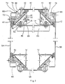
- an electrical equipment housing cabinet is constituted by the assembly of 12 angular elements forming a right rectangular parallelepiped.
- the sections 10,12,14,16 forming the uprights or vertical angular elements as well as the sections 18,20,22,24 of the upper part of the frame, and the sections 26,28,30,32 of the lower part of the frame are all identical and arranged in the same way.
- the sections 10 to 32 have an angle part 34, the two sides 36,38 of which are orthogonal and have longitudinal edges folded at right angles to obtain a directed fold 40,42 towards the inside.
- the edges 44,46 formed by the folded edges 40,42 are connected by an exterior partition 48 confining with the angle iron 34 a tubular internal space 50 of triangular section.
- the two sides 36, 38 of the angle iron 34 are provided rows of perforations 52 for fixing crosspieces 53 supporting the electrical apparatus housed in the cabinet in a manner well known to specialists.
- the crosspieces 53 are fixed to the angles 34 by bolts, the nuts of which are inserted in the profile.
- the external partition 48 which extends along the hypotenuse of the triangular profile is a solid partition or provided with a limited number of fixing perforations whose usefulness will be described later.
- the frame of the cabinet is covered with panels 54.56 respectively on the rear face and on the front face of the cabinet as well as panels 58.60 on the lateral faces and 62.64 at the base and at the top of the wardrobe.
- These panels are each constituted by a sheet metal plate whose edges 66 are folded at right angles to ensure the rigidity of the panel.
- the sections 10 to 32 are all arranged in the same way with the edge 68 of the angle iron 34, corresponding to the apex of the right angle of the right triangle, oriented towards the inside of the cabinet.
- the panels 54 to 64 cooperate with the edges 44 and 46 of the folded or folded edges 40,42 with the interposition of seals 70 in the form of a bead extending around the periphery of the panel.
- the panels 54 to 64 are fixed to the sections 10 to 32 by screws 72 which are screwed into intermediate pieces 74 attached to the external partition 48.
- the fixing of the intermediate pieces can be carried out by any suitable means, for example by gluing or simply by bolts passing through orifices in the partition 48.
- the same intermediate piece 74 serves to fix the two panels forming the corresponding angle of the cabinet.
- This intermediate piece fits into the external template of the profile and has a cutout 76 for housing the edges 66 of the panels 54 to 64.
- the fixing of the panels 54 to 64 can of course be carried out in a different manner, the screws 72 being able to for example take support on the folds 40,42 or directly on the partition 48.
- the corresponding intermediate piece 78 is shaped to constitute a hinge 80 for supporting the door 56.
- the hinge 80 fits into the external template of the profile.
- the opposite intermediate piece, arranged on the movable side of the door 56, can be identical to the others, or be devoid of one of the fixing points made unnecessary by the presence of the door 56.
- all of the seals 70 cooperating with the vertical sections 10 to 16 cooperate with the edges 44,46, formed by the folded edges 40,42.
- the seal between two adjacent panels, for example the panels 54, 60 being produced by means of the seals 70 and the external partition 48.
- the partition 48 constitutes a separation from a sealed internal zone, in which the sides 36, 38 of the angle iron 34 on which the crosspieces or other rails supporting the apparatus can be fixed.
- On the external side of the partition 48 extends a non-sealed area used for fixing to the intermediate parts 74, 78 with their accessories, such as the hinge 80 or the fixing screws 72.
- the profiles forming horizontal crosspieces can be sealed in the same way by making the seals 70 cooperate with the edges 44, 46 but according to a preferred embodiment of the invention, represented in FIG. 3, the seal 70 above the door 56 or advantageously all the seals 70, interposed between the vertical panels 54,56,58,60 and the horizontal upper sections 18,20,22,24, are slightly offset upwards so as to cooperate with edge 84 folds 40.42. It is easy to see that this offset avoids any accumulation of water between the panels and the folds 40, 42 which could affect the tightness of the cabinet or cause water penetration when the door is opened. 56.
- the sections 10 to 32 are assembled at their ends by cubic pieces 86 having three orthogonal legs which fit into the triangular ends of the sections. These parts are strictly identical, whatever their position. This assembly can of course be carried out in another way, for example by welding.
- the cabinet according to the invention is produced in the following manner:
- the standard sections 10 to 32 of appropriate length are assembled by cubic pieces 86 arranged at the corners of the cabinet, taking care to orient the edge 68 of the angles towards the interior of the cabinet.
- the perfect symmetry of the profiles avoids any assembly error and it is possible to produce a whole range of cupboards, either by cutting the profiles on demand, or by providing a stock of profiles of different length, in particular with a modularity of 25 mm in the three dimensions.
- the profiles 10 to 32 assembled constitute a solid framework or frame used for fixing to the covering panels 54 to 64 as well as to the crosspieces 53 or support rails of the devices housed inside the cabinet.
- the panels 54 to 64 of appropriate dimensions are then fixed to the different faces of the cabinet, taking care to interpose the seals 70 between the profiles and the edges of the panels.
- the door 56 is of course fixed by the hinge 80 carried by the intermediate piece 78, and a lock (not shown) is disposed on the opposite edge of the door 56 in a manner well known to specialists.
- the apparatus can of course be put in place in the cabinet before all or some of the panels 54 to 64 are fixed.
- the dismantling of the panels or of the cabinet is extremely simple and it is possible to attach several frames to each other. to others as well laterally, in depth or in height while maintaining the seal and retaining the same exterior panels.
- Profiles 10 to 32 can be produced by any suitable means, for example by extrusion, but according to a preferred method, they are obtained by folding a sheet metal strip, for example on an automatic roller burnishing machine.
- FIG. 4 represents an embodiment with six folds, the edges of the folded strip being stapled at the level of the fold 40, which has three thicknesses of superposed sheets. Rounded edges are thus obtained capable of cooperating with the seals 70 without risk of deterioration.
- the opposite fold 42 consists of a simple fold and therefore of two sheet thicknesses. The symmetry can be preserved by providing an empty space 86 between the folded parts to give this fold 42 a thickness comparable to or equal to that of the fold 40 with three thicknesses.
- FIG. 5 illustrates an alternative embodiment in which the thickness of the fold 42 is increased by the insertion of a wedge 88 replacing the void 86 between the folded edges of the fold 42.
- the profile has a wing 90 which extends along the edge 68 of the angle iron 34, projecting towards the inside of the cabinet .
- the wing 90 has perforations 92 for fixing the internal elements of the cabinet.
- the wing 90 extends in the plane of one 38 of the sides of the angle iron ( Figure 6) or in any other direction, in particular in the bisector plane of the angle iron ( Figure 7) and it is constituted by a fold of sheet metal as shown on the figures.
- the structure according to the invention gives the profile great rigidity with respect to the weight and provides a seal while retaining the external template of the cabinet allowing easy juxtaposition of several frames.
- FIG. 4 represents a nut 100 mounted in a cage 102 in the shape of a stirrup.
- Profile 10-32 has perforations 104 on the edge 68 at a pitch and at the level of the perforations 52 on the sides 36, 38 to allow introduction of the nut 100 inside the profile while being retained by the stirrup 102 overlapping the side.
- the cage 102 in folded steel has a lug 106, which under the clamping force is embedded in the profile to ensure electrical continuity.
- a folded tab 108 fits into the perforation 52 to center the nut.
Applications Claiming Priority (2)
| Application Number | Priority Date | Filing Date | Title |
|---|---|---|---|
| FR8907506 | 1989-06-05 | ||
| FR8907506A FR2648005B1 (fr) | 1989-06-05 | 1989-06-05 | Armoire etanche d'appareillage electrique |
Publications (2)
| Publication Number | Publication Date |
|---|---|
| EP0402276A1 true EP0402276A1 (de) | 1990-12-12 |
| EP0402276B1 EP0402276B1 (de) | 1993-03-17 |
Family
ID=9382454
Family Applications (1)
| Application Number | Title | Priority Date | Filing Date |
|---|---|---|---|
| EP90420242A Expired - Lifetime EP0402276B1 (de) | 1989-06-05 | 1990-05-18 | Abgedichteter Schaltschrank |
Country Status (19)
| Country | Link |
|---|---|
| US (1) | US5202818A (de) |
| EP (1) | EP0402276B1 (de) |
| JP (1) | JPH0322593A (de) |
| CN (1) | CN1021402C (de) |
| AT (1) | ATE87169T1 (de) |
| AU (1) | AU624717B2 (de) |
| BR (1) | BR9002637A (de) |
| CA (1) | CA2017594A1 (de) |
| DE (1) | DE69001096T2 (de) |
| DK (1) | DK0402276T3 (de) |
| EG (1) | EG19454A (de) |
| ES (1) | ES2040581T3 (de) |
| FI (1) | FI902752A0 (de) |
| FR (1) | FR2648005B1 (de) |
| MX (1) | MX174607B (de) |
| NO (1) | NO902461L (de) |
| PT (1) | PT94262A (de) |
| TR (1) | TR24645A (de) |
| ZA (1) | ZA904255B (de) |
Cited By (10)
| Publication number | Priority date | Publication date | Assignee | Title |
|---|---|---|---|---|
| FR2681404A1 (fr) * | 1991-09-18 | 1993-03-19 | Legrand Sa | Profile d'ossature sur lequel doit etre rapporte un accessoire d'equipement, et accessoires d'equipement susceptibles d'etre associes a un tel profile d'ossature. |
| ES2039170A2 (es) * | 1991-12-17 | 1993-08-16 | Legrand Sa | Panel, en particular para puerta de armario, y especialmente para puerta de armario electrico. |
| EP0572601A1 (de) * | 1991-11-27 | 1993-12-08 | FEDERAL-HOFFMAN, INC., d/b/a HOFFMAN ENGINEERING COMPANY | Modulares, mehrseitiges schrankgestell mit integriertem führungssystem für plattenteile |
| EP0574560A1 (de) * | 1991-11-27 | 1993-12-22 | Federal Hoffman Inc D B A Hoff | Gehäuse mit verändebarer struktur und vielfach vervendbaren montageblöcken. |
| FR2708391A1 (fr) * | 1993-07-27 | 1995-02-03 | Gec Alsthom Equip Basse Tens | Profilé de construction pour chassis d'armoire électrique. |
| WO1995012232A1 (de) * | 1993-10-25 | 1995-05-04 | Rittal-Werk Rudolf Loh Gmbh & Co. Kg | Rahmengestell für einen schaltschrank |
| FR2741231A1 (fr) * | 1995-10-04 | 1997-05-16 | Loh Kg Rittal Werk | Branche d'encadrement pour bati d'encadrement d'une armoire de commutation |
| DE19647723C1 (de) * | 1996-11-19 | 1998-04-09 | Loh Kg Rittal Werk | Rahmengestell für einen Schaltschrank |
| DE4132803C3 (de) * | 1991-10-02 | 2000-03-16 | Loh Kg Rittal Werk | Hohlprofil für ein Rahmengestell eines Schaltschrankes |
| WO2012113551A1 (de) * | 2011-02-25 | 2012-08-30 | C E S Control Enclosure Systems Gmbh | Dichtelement und dichtungssystem für hohlprofile |
Families Citing this family (50)
| Publication number | Priority date | Publication date | Assignee | Title |
|---|---|---|---|---|
| DE4140072A1 (de) * | 1991-12-05 | 1993-06-09 | Rittal-Werk Rudolf Loh Gmbh & Co Kg, 6348 Herborn, De | Schaltschrank mit rahmengestell und montageplatte |
| JP2817527B2 (ja) * | 1992-08-11 | 1998-10-30 | 日本電気株式会社 | フレーム組立 |
| DE4333027C1 (de) * | 1993-09-28 | 1994-10-06 | Loh Kg Rittal Werk | Gestellrahmen |
| FR2711454B1 (fr) * | 1993-10-18 | 1995-11-24 | Merlin Gerin | Liaison d'angle pour armoire, et armoire électrique comportant de telles liaisons. |
| DE4439628C2 (de) * | 1994-11-05 | 1998-11-26 | Loh Kg Rittal Werk | Rahmengestell aus Rahmenschenkeln und Tiefenstreben |
| DE19536950C1 (de) * | 1995-10-04 | 1996-11-21 | Loh Kg Rittal Werk | Rahmenschenkel für ein Rahmengestell eines Schaltschrankes |
| US5673985A (en) * | 1996-06-25 | 1997-10-07 | Mitchell; Jerry B. | Modular electronic components cabinet structure |
| US5964361A (en) * | 1997-02-21 | 1999-10-12 | Frazier Industrial Company | Ergonomic storage racks |
| DE19707929C1 (de) * | 1997-02-27 | 1998-09-03 | Schroff Gmbh | Schrank zur Aufnahme von elektrischen und elektronischen Komponenten |
| US5997117A (en) * | 1997-06-06 | 1999-12-07 | Chatsworth Products, Inc. | Rack frame cabinet |
| DE19813222C1 (de) * | 1998-03-26 | 1999-11-25 | Loh Kg Rittal Werk | Rahmengestell für einen Schaltschrank |
| DE19817916A1 (de) * | 1998-04-17 | 1999-10-21 | Loh Kg Rittal Werk | Rahmenschenkel für ein Rahmengestell eines Schaltschrankes |
| DE19816945A1 (de) * | 1998-04-17 | 1999-10-21 | Loh Kg Rittal Werk | Schaltschrank |
| DE19817245A1 (de) * | 1998-04-18 | 1999-10-28 | Loh Kg Rittal Werk | Schaltschrank |
| DE19818603A1 (de) * | 1998-04-20 | 1999-10-21 | Loh Kg Rittal Werk | Rahmenschenkel für ein Rahmengestell eines Schaltschrankes |
| NO308820B1 (no) * | 1998-04-27 | 2000-10-30 | Efa Elektro As | Skap med i det minste én dør, særlig et elektroskap |
| FR2796519B1 (fr) * | 1999-07-16 | 2003-04-11 | Socomec Sa | Armoire, notamment armoire electronique de commande et armoires juxtaposees |
| US20040183409A1 (en) * | 2001-01-23 | 2004-09-23 | Cooper Technologies Company | Electrical equipment enclosure |
| DE10207364B4 (de) * | 2001-03-01 | 2007-06-14 | Nitto Electric Works, Ltd. | Gestellglied für Gehäuse von elektrischen und elektronischen Geräten und Gestellglied-Verbindungskonstruktion |
| DE10113935C1 (de) * | 2001-03-21 | 2002-10-10 | Rittal Rcs Comm Systems Gmbh & Co Kg | Schaltschrank mit Rahmengestell und Verkleidungselementen |
| DE10113936C1 (de) * | 2001-03-21 | 2002-10-10 | Rittal Rcs Comm Systems Gmbh & Co Kg | Schaltschrank mit Rahmengestell und Verkleidungselementen |
| US6481582B1 (en) | 2001-06-04 | 2002-11-19 | Cooper Technologies Company | Rack |
| US6974036B2 (en) * | 2002-04-01 | 2005-12-13 | Viasystems Group, Inc. | Corner post and manufacturing process for making same |
| BR0301083A (pt) * | 2003-04-03 | 2004-11-03 | Melquisedec Francisquini | Aperfeiçoamento em perfil metálico para composição de estruturas para montagem de quadros elétricos |
| DE10342546A1 (de) * | 2003-09-12 | 2005-06-30 | Abb Patent Gmbh | Schaltschrank für Niederspannungsschaltanlagen |
| US8016126B1 (en) * | 2003-09-30 | 2011-09-13 | Google Inc. | Cabinet structures resistant to racking deformation for rack mounted computing systems |
| US20060059790A1 (en) * | 2004-08-31 | 2006-03-23 | Yeung Hubert K | Systems and methods for modular instrument design and fabrication |
| FR2896631B1 (fr) * | 2006-01-25 | 2009-07-31 | Legrand France | Armoire pour appareils electriques comportant une armature et un clips-ecrou monte sur un profile appartenant a l'armature |
| US7718891B2 (en) * | 2006-03-13 | 2010-05-18 | Panduit Corp. | Network cabinet |
| JP2007312545A (ja) * | 2006-05-19 | 2007-11-29 | Fuji Electric Fa Components & Systems Co Ltd | インバータ装置の筐体構造およびその製造方法 |
| USD630173S1 (en) | 2009-04-20 | 2011-01-04 | Chatsworth Products, Inc. | Cover for electronic equipment cabinet |
| USD632660S1 (en) | 2009-04-20 | 2011-02-15 | Chatsworth Products, Inc. | Cover for electronic equipment cabinet |
| US20110296675A1 (en) * | 2009-08-26 | 2011-12-08 | Roopnarine | Means for rapidly assembling a spacecraft |
| US8403431B2 (en) * | 2009-09-01 | 2013-03-26 | Emerson Network Power, Energy Systems, North America, Inc. | Telecommunications enclosures |
| CN102137553A (zh) * | 2010-01-25 | 2011-07-27 | 鸿富锦精密工业(深圳)有限公司 | 机柜及其装配方法 |
| DE102010034620A1 (de) * | 2010-08-17 | 2012-02-23 | Adc Gmbh | Verteilerschrank |
| ITAN20110079U1 (it) * | 2010-11-23 | 2012-05-24 | Tekpan Teknik Elek K Kumanda Pano Sanayi Ve Turi | Sistema di assemblaggio angolare di profili di costruzione. |
| CN103476999B (zh) | 2011-02-25 | 2015-06-24 | Ces控制机柜系统有限公司 | 从扁平片状金属生产矩形或正方形壁元件的方法及由此生产的壁元件 |
| JP2014510882A (ja) | 2011-02-25 | 2014-05-01 | シー イー エス コントロール エンクロージャー システムズ ゲーエムベーハー | 中空プロフィールのためのコーナーコネクター |
| DE102014101401A1 (de) * | 2014-02-05 | 2015-08-06 | Rittal Gmbh & Co. Kg | Anreih-Schaltschranksystem |
| DE102014101404B4 (de) * | 2014-02-05 | 2017-11-16 | Rittal Gmbh & Co. Kg | Rahmengestell für einen Schalt- oder Verteilerschrank |
| GB2529827B (en) * | 2014-09-02 | 2017-01-04 | Cp Cases Ltd | Electronic rack and mounting chassis |
| JP6512939B2 (ja) * | 2015-05-26 | 2019-05-15 | 日東工業株式会社 | 電気機器収納用箱 |
| CN108012471A (zh) * | 2016-10-31 | 2018-05-08 | 鸿富锦精密电子(天津)有限公司 | 服务器立柱 |
| DE102017108335B4 (de) * | 2017-04-19 | 2019-01-03 | Rittal Gmbh & Co. Kg | Befestigungsanordnung und ein entsprechendes Schaltschrankgehäuse |
| CN207219192U (zh) * | 2017-06-05 | 2018-04-10 | 阳光电源股份有限公司 | 户外柜及其顶部结构 |
| BR102019010955B1 (pt) * | 2019-05-28 | 2023-04-11 | Melquisedec Francisquini | Perfil estrutural para armário elétrico |
| FR3097714B1 (fr) * | 2019-06-24 | 2023-02-10 | Schneider Electric Ind Sas | Armature pour une armoire électrique, armoire électrique comportant une telle armature |
| US11576277B2 (en) * | 2020-02-14 | 2023-02-07 | Quanta Computer Inc. | Rack for supporting servers of varying heights |
| CN114614176A (zh) * | 2022-03-25 | 2022-06-10 | 中创新航科技股份有限公司 | 储能机架 |
Citations (2)
| Publication number | Priority date | Publication date | Assignee | Title |
|---|---|---|---|---|
| DE8335383U1 (de) * | 1983-12-09 | 1984-04-05 | Rittal-Werk Rudolf Loh Gmbh & Co Kg, 6348 Herborn | Rahmengestell für einen Schaltschrank |
| EP0281983A2 (de) * | 1987-03-12 | 1988-09-14 | Fischbach GmbH & Co.KG | Stecksystem zum Aufbau eines Gehäuserahmens |
Family Cites Families (10)
| Publication number | Priority date | Publication date | Assignee | Title |
|---|---|---|---|---|
| FR2278223A1 (fr) * | 1974-07-08 | 1976-02-06 | France Etat | Bati pour equipements electroniques |
| SU586578A1 (ru) * | 1975-03-31 | 1977-12-30 | Предприятие П/Я В-2502 | Шкаф дл радиоэлектронной аппаратуры |
| AU522557B2 (en) * | 1975-10-08 | 1982-06-17 | N.G. Ford | Packaging of electrical or electronic components |
| JPS56118688A (en) * | 1980-02-25 | 1981-09-17 | Matsushita Electric Works Ltd | Alarm clock |
| JPS58156659A (ja) * | 1982-03-15 | 1983-09-17 | 三菱製鋼株式会社 | 緩衝床 |
| BR8704944A (pt) * | 1986-09-26 | 1988-05-17 | Vormet Quality Fab Close Corp | Bloco esquinado para unir os membros de uma estrutura prismatica retangular e estrutura prismatica retangular |
| DE3633284A1 (de) * | 1986-09-30 | 1988-04-07 | Loh Kg Rittal Werk | Mehrzweck-tischgehaeuse |
| US4754368A (en) * | 1987-04-09 | 1988-06-28 | General Electric Company | Terminal for watthour meters |
| US4814942A (en) * | 1987-08-10 | 1989-03-21 | Westinghouse Electric Corp. | Drawout switchgear cell frame |
| US5001602A (en) * | 1988-11-28 | 1991-03-19 | Reliance Comm/Tec Corporation | Network interface cabinet for large pair count telephone terminations |
-
1989
- 1989-06-05 FR FR8907506A patent/FR2648005B1/fr not_active Expired - Fee Related
-
1990
- 1990-05-18 DK DK90420242.1T patent/DK0402276T3/da active
- 1990-05-18 DE DE9090420242T patent/DE69001096T2/de not_active Expired - Fee Related
- 1990-05-18 ES ES199090420242T patent/ES2040581T3/es not_active Expired - Lifetime
- 1990-05-18 AT AT90420242T patent/ATE87169T1/de not_active IP Right Cessation
- 1990-05-18 EP EP90420242A patent/EP0402276B1/de not_active Expired - Lifetime
- 1990-05-25 CA CA002017594A patent/CA2017594A1/en not_active Abandoned
- 1990-05-29 US US07/529,542 patent/US5202818A/en not_active Expired - Fee Related
- 1990-05-31 MX MX020953A patent/MX174607B/es unknown
- 1990-06-01 NO NO90902461A patent/NO902461L/no unknown
- 1990-06-01 FI FI902752A patent/FI902752A0/fi not_active IP Right Cessation
- 1990-06-01 AU AU56201/90A patent/AU624717B2/en not_active Ceased
- 1990-06-04 PT PT94262A patent/PT94262A/pt not_active Application Discontinuation
- 1990-06-04 CN CN90104072A patent/CN1021402C/zh not_active Expired - Fee Related
- 1990-06-04 ZA ZA904255A patent/ZA904255B/xx unknown
- 1990-06-04 JP JP2146041A patent/JPH0322593A/ja active Pending
- 1990-06-04 BR BR909002637A patent/BR9002637A/pt not_active IP Right Cessation
- 1990-06-05 EG EG33090A patent/EG19454A/xx active
- 1990-06-20 TR TR90/0522A patent/TR24645A/xx unknown
Patent Citations (2)
| Publication number | Priority date | Publication date | Assignee | Title |
|---|---|---|---|---|
| DE8335383U1 (de) * | 1983-12-09 | 1984-04-05 | Rittal-Werk Rudolf Loh Gmbh & Co Kg, 6348 Herborn | Rahmengestell für einen Schaltschrank |
| EP0281983A2 (de) * | 1987-03-12 | 1988-09-14 | Fischbach GmbH & Co.KG | Stecksystem zum Aufbau eines Gehäuserahmens |
Cited By (21)
| Publication number | Priority date | Publication date | Assignee | Title |
|---|---|---|---|---|
| FR2681404A1 (fr) * | 1991-09-18 | 1993-03-19 | Legrand Sa | Profile d'ossature sur lequel doit etre rapporte un accessoire d'equipement, et accessoires d'equipement susceptibles d'etre associes a un tel profile d'ossature. |
| EP0533555A1 (de) * | 1991-09-18 | 1993-03-24 | Legrand | Skelettprofil mit einer Zubehöranordnung |
| DE4132803C3 (de) * | 1991-10-02 | 2000-03-16 | Loh Kg Rittal Werk | Hohlprofil für ein Rahmengestell eines Schaltschrankes |
| US5407263A (en) * | 1991-11-27 | 1995-04-18 | Federal-Hoffman, Inc. | Restructurable enclosure with multi-purpose mounting blocks |
| EP0572601A4 (de) * | 1991-11-27 | 1994-03-30 | Federal-Hoffman, Inc., D/B/A Hoffman Engineering Company | |
| EP0574560A4 (de) * | 1991-11-27 | 1994-03-30 | Federal-Hoffman, Inc., D/B/A Hoffman Engineering Company | |
| US5380083A (en) * | 1991-11-27 | 1995-01-10 | Federal-Hoffman, Inc. | Multifaceted modular enclosure frame with integral sub-panel guide system |
| EP0574560A1 (de) * | 1991-11-27 | 1993-12-22 | Federal Hoffman Inc D B A Hoff | Gehäuse mit verändebarer struktur und vielfach vervendbaren montageblöcken. |
| US5388903A (en) * | 1991-11-27 | 1995-02-14 | Federal-Hoffman, Inc. | Multifaceted modular enclosure frame with integral sub-panel guide system |
| EP0572601A1 (de) * | 1991-11-27 | 1993-12-08 | FEDERAL-HOFFMAN, INC., d/b/a HOFFMAN ENGINEERING COMPANY | Modulares, mehrseitiges schrankgestell mit integriertem führungssystem für plattenteile |
| ES2039170A2 (es) * | 1991-12-17 | 1993-08-16 | Legrand Sa | Panel, en particular para puerta de armario, y especialmente para puerta de armario electrico. |
| FR2708391A1 (fr) * | 1993-07-27 | 1995-02-03 | Gec Alsthom Equip Basse Tens | Profilé de construction pour chassis d'armoire électrique. |
| EP0751595A2 (de) * | 1993-10-25 | 1997-01-02 | Rittal-Werk Rudolf Loh GmbH & Co. KG | Rahmengestell für einen Schaltschrank |
| EP0751595A3 (de) * | 1993-10-25 | 1997-01-15 | Rittal-Werk Rudolf Loh GmbH & Co. KG | Rahmengestell für einen Schaltschrank |
| WO1995012232A1 (de) * | 1993-10-25 | 1995-05-04 | Rittal-Werk Rudolf Loh Gmbh & Co. Kg | Rahmengestell für einen schaltschrank |
| FR2741231A1 (fr) * | 1995-10-04 | 1997-05-16 | Loh Kg Rittal Werk | Branche d'encadrement pour bati d'encadrement d'une armoire de commutation |
| DE19647723C1 (de) * | 1996-11-19 | 1998-04-09 | Loh Kg Rittal Werk | Rahmengestell für einen Schaltschrank |
| WO2012113551A1 (de) * | 2011-02-25 | 2012-08-30 | C E S Control Enclosure Systems Gmbh | Dichtelement und dichtungssystem für hohlprofile |
| JP2014513779A (ja) * | 2011-02-25 | 2014-06-05 | シー イー エス コントロール エンクロージャー システムズ ゲーエムベーハー | 中空区画のためのシーリング要素及びシーリング・システム |
| RU2582076C2 (ru) * | 2011-02-25 | 2016-04-20 | С Е С Контрол Энкложе Системз Гмбх | Уплотнительный элемент и уплотнительная система для полых профилей |
| US9383016B2 (en) | 2011-02-25 | 2016-07-05 | C E S Control Enclosure Systems Gmbh | Sealing element and a sealing system for hollow sections |
Also Published As
| Publication number | Publication date |
|---|---|
| US5202818A (en) | 1993-04-13 |
| ATE87169T1 (de) | 1993-04-15 |
| FR2648005B1 (fr) | 1993-11-26 |
| DE69001096D1 (de) | 1993-04-22 |
| TR24645A (tr) | 1992-01-01 |
| EG19454A (en) | 1995-04-30 |
| CA2017594A1 (en) | 1990-12-05 |
| DE69001096T2 (de) | 1993-09-16 |
| ZA904255B (en) | 1991-03-27 |
| BR9002637A (pt) | 1991-08-20 |
| DK0402276T3 (da) | 1993-07-12 |
| PT94262A (pt) | 1991-02-08 |
| ES2040581T3 (es) | 1993-10-16 |
| NO902461D0 (no) | 1990-06-01 |
| CN1021402C (zh) | 1993-06-23 |
| EP0402276B1 (de) | 1993-03-17 |
| AU624717B2 (en) | 1992-06-18 |
| AU5620190A (en) | 1990-12-06 |
| FR2648005A1 (fr) | 1990-12-07 |
| NO902461L (no) | 1990-12-06 |
| CN1048300A (zh) | 1991-01-02 |
| JPH0322593A (ja) | 1991-01-30 |
| MX174607B (es) | 1994-05-30 |
| FI902752A0 (fi) | 1990-06-01 |
Similar Documents
| Publication | Publication Date | Title |
|---|---|---|
| EP0402276B1 (de) | Abgedichteter Schaltschrank | |
| EP0649205B1 (de) | Schrank mit Eckverbindung und ein Schaltschrank mit solchen Verbindungen | |
| FR2683956A1 (fr) | Chassis-cadre pour une armoire electrique. | |
| CH677688A5 (de) | ||
| EP1601074A1 (de) | Schaltschrank mit Rahmenprofilen | |
| EP2107654B1 (de) | Zusammenbau eines Stromkastens | |
| WO1997038921A1 (fr) | Paroi ou enveloppe formee de feuilles de tole tendues sur une ossature ou une charpente et son procede de construction | |
| FR2702314A1 (fr) | Armoire métallique, notamment pour le logement d'un appareillage électrique modulaire. | |
| FR2914117A1 (fr) | Montant ouvert renforce pour armoire electrique | |
| EP0008970A1 (de) | Metallschrank | |
| FR2956198A1 (fr) | Dispositif pour la fixation de panneaux solaires comportant des profiles lateraux munis d'une gorge longitudinale ouverte vers le bas | |
| FR2956681A1 (fr) | Dispositif pour l'integration de panneaux photovoltaiques sur un toit | |
| FR2961298A1 (fr) | Structure-support pour panneau et installation correspondante. | |
| FR2958378A1 (fr) | Installation solaire destinee a etre posee sur une partie de la surface d'une structure support en pente | |
| EP0886354B1 (de) | Metallschrank für elektrische Geräte | |
| FR2681405A1 (fr) | Piece d'assemblage pour ossature d'armoire, notamment pour appareillages electriques, et ossature et armoire correspondantes. | |
| EP2053189A2 (de) | Rahmen mit Fenster- oder Türflügel | |
| EP0821113B1 (de) | Senkrechtes Trennwandsystem mit Verbindungsklammern | |
| FR2883313A1 (fr) | Ossature de cloison demontable ou amovible a double paroi | |
| EP2530404A2 (de) | Modulare Abdeckvorrichtung | |
| FR2539336A1 (fr) | Cabine de peinture en panneaux modulaires | |
| FR2958953A1 (fr) | Couverture photovoltaique integrable constituee de panneaux assembles de maniere etanche et demontable | |
| FR2511410A1 (fr) | Construction en elements prefabriques notamment pour la realisation de bungalows, de garages, d'abris... | |
| FR2976007A1 (fr) | Dispositif de couverture modulaire | |
| EP2871298A1 (de) | Modulsystem zum Bau von Gebäuden, das mit Platinen befestigte Module umfasst |
Legal Events
| Date | Code | Title | Description |
|---|---|---|---|
| PUAI | Public reference made under article 153(3) epc to a published international application that has entered the european phase |
Free format text: ORIGINAL CODE: 0009012 |
|
| AK | Designated contracting states |
Kind code of ref document: A1 Designated state(s): AT BE CH DE DK ES GB IT LI SE |
|
| 17P | Request for examination filed |
Effective date: 19910522 |
|
| 17Q | First examination report despatched |
Effective date: 19920724 |
|
| GRAA | (expected) grant |
Free format text: ORIGINAL CODE: 0009210 |
|
| AK | Designated contracting states |
Kind code of ref document: B1 Designated state(s): AT BE CH DE DK ES GB IT LI SE |
|
| REF | Corresponds to: |
Ref document number: 87169 Country of ref document: AT Date of ref document: 19930415 Kind code of ref document: T |
|
| REF | Corresponds to: |
Ref document number: 69001096 Country of ref document: DE Date of ref document: 19930422 |
|
| ITF | It: translation for a ep patent filed |
Owner name: INTERPATENT ST.TECN. BREV. |
|
| GBT | Gb: translation of ep patent filed (gb section 77(6)(a)/1977) |
Effective date: 19930603 |
|
| REG | Reference to a national code |
Ref country code: DK Ref legal event code: T3 |
|
| REG | Reference to a national code |
Ref country code: ES Ref legal event code: FG2A Ref document number: 2040581 Country of ref document: ES Kind code of ref document: T3 |
|
| PLBI | Opposition filed |
Free format text: ORIGINAL CODE: 0009260 |
|
| 26 | Opposition filed |
Opponent name: RITTAL-WERK RUDOLF LOH GMBH & CO. KG Effective date: 19931124 |
|
| EAL | Se: european patent in force in sweden |
Ref document number: 90420242.1 |
|
| PLBO | Opposition rejected |
Free format text: ORIGINAL CODE: EPIDOS REJO |
|
| PLBO | Opposition rejected |
Free format text: ORIGINAL CODE: EPIDOS REJO |
|
| PLBN | Opposition rejected |
Free format text: ORIGINAL CODE: 0009273 |
|
| STAA | Information on the status of an ep patent application or granted ep patent |
Free format text: STATUS: OPPOSITION REJECTED |
|
| 27O | Opposition rejected |
Effective date: 19960916 |
|
| PGFP | Annual fee paid to national office [announced via postgrant information from national office to epo] |
Ref country code: SE Payment date: 19990414 Year of fee payment: 10 |
|
| PGFP | Annual fee paid to national office [announced via postgrant information from national office to epo] |
Ref country code: GB Payment date: 19990512 Year of fee payment: 10 Ref country code: DK Payment date: 19990512 Year of fee payment: 10 Ref country code: AT Payment date: 19990512 Year of fee payment: 10 |
|
| PGFP | Annual fee paid to national office [announced via postgrant information from national office to epo] |
Ref country code: CH Payment date: 19990526 Year of fee payment: 10 |
|
| PGFP | Annual fee paid to national office [announced via postgrant information from national office to epo] |
Ref country code: BE Payment date: 19990728 Year of fee payment: 10 |
|
| PG25 | Lapsed in a contracting state [announced via postgrant information from national office to epo] |
Ref country code: GB Free format text: LAPSE BECAUSE OF NON-PAYMENT OF DUE FEES Effective date: 20000518 Ref country code: DK Free format text: LAPSE BECAUSE OF NON-PAYMENT OF DUE FEES Effective date: 20000518 Ref country code: AT Free format text: LAPSE BECAUSE OF NON-PAYMENT OF DUE FEES Effective date: 20000518 |
|
| PG25 | Lapsed in a contracting state [announced via postgrant information from national office to epo] |
Ref country code: SE Free format text: LAPSE BECAUSE OF NON-PAYMENT OF DUE FEES Effective date: 20000519 |
|
| PG25 | Lapsed in a contracting state [announced via postgrant information from national office to epo] |
Ref country code: LI Free format text: LAPSE BECAUSE OF NON-PAYMENT OF DUE FEES Effective date: 20000531 Ref country code: CH Free format text: LAPSE BECAUSE OF NON-PAYMENT OF DUE FEES Effective date: 20000531 Ref country code: BE Free format text: LAPSE BECAUSE OF NON-PAYMENT OF DUE FEES Effective date: 20000531 |
|
| BERE | Be: lapsed |
Owner name: MERLIN GERIN Effective date: 20000531 |
|
| GBPC | Gb: european patent ceased through non-payment of renewal fee |
Effective date: 20000518 |
|
| REG | Reference to a national code |
Ref country code: CH Ref legal event code: PL |
|
| EUG | Se: european patent has lapsed |
Ref document number: 90420242.1 |
|
| REG | Reference to a national code |
Ref country code: DK Ref legal event code: EBP |
|
| PG25 | Lapsed in a contracting state [announced via postgrant information from national office to epo] |
Ref country code: IT Free format text: LAPSE BECAUSE OF NON-PAYMENT OF DUE FEES Effective date: 20050518 |
|
| PGFP | Annual fee paid to national office [announced via postgrant information from national office to epo] |
Ref country code: DE Payment date: 20070516 Year of fee payment: 18 |
|
| PGFP | Annual fee paid to national office [announced via postgrant information from national office to epo] |
Ref country code: ES Payment date: 20070621 Year of fee payment: 18 |
|
| PLAB | Opposition data, opponent's data or that of the opponent's representative modified |
Free format text: ORIGINAL CODE: 0009299OPPO |
|
| PG25 | Lapsed in a contracting state [announced via postgrant information from national office to epo] |
Ref country code: DE Free format text: LAPSE BECAUSE OF NON-PAYMENT OF DUE FEES Effective date: 20081202 |
|
| REG | Reference to a national code |
Ref country code: ES Ref legal event code: FD2A Effective date: 20080519 |
|
| PG25 | Lapsed in a contracting state [announced via postgrant information from national office to epo] |
Ref country code: ES Free format text: LAPSE BECAUSE OF NON-PAYMENT OF DUE FEES Effective date: 20080519 |