EP0401762A2 - Vibration driven motor - Google Patents
Vibration driven motor Download PDFInfo
- Publication number
- EP0401762A2 EP0401762A2 EP90110633A EP90110633A EP0401762A2 EP 0401762 A2 EP0401762 A2 EP 0401762A2 EP 90110633 A EP90110633 A EP 90110633A EP 90110633 A EP90110633 A EP 90110633A EP 0401762 A2 EP0401762 A2 EP 0401762A2
- Authority
- EP
- European Patent Office
- Prior art keywords
- vibration
- vibration member
- driven motor
- supporting
- loop
- Prior art date
- Legal status (The legal status is an assumption and is not a legal conclusion. Google has not performed a legal analysis and makes no representation as to the accuracy of the status listed.)
- Granted
Links
- 239000002783 friction material Substances 0.000 claims description 5
- 239000004809 Teflon Substances 0.000 claims description 3
- 229920006362 Teflon® Polymers 0.000 claims description 3
- 230000001131 transforming effect Effects 0.000 claims 6
- 238000000429 assembly Methods 0.000 description 12
- 230000000712 assembly Effects 0.000 description 12
- 238000006073 displacement reaction Methods 0.000 description 4
- 230000004048 modification Effects 0.000 description 4
- 238000012986 modification Methods 0.000 description 4
- 230000008602 contraction Effects 0.000 description 2
- 238000000034 method Methods 0.000 description 2
- 230000010287 polarization Effects 0.000 description 2
- 238000005452 bending Methods 0.000 description 1
- 239000004020 conductor Substances 0.000 description 1
- 230000007423 decrease Effects 0.000 description 1
- 238000010586 diagram Methods 0.000 description 1
- 238000002474 experimental method Methods 0.000 description 1
- 230000000717 retained effect Effects 0.000 description 1
Images


Classifications
-
- H—ELECTRICITY
- H02—GENERATION; CONVERSION OR DISTRIBUTION OF ELECTRIC POWER
- H02N—ELECTRIC MACHINES NOT OTHERWISE PROVIDED FOR
- H02N2/00—Electric machines in general using piezoelectric effect, electrostriction or magnetostriction
-
- H—ELECTRICITY
- H02—GENERATION; CONVERSION OR DISTRIBUTION OF ELECTRIC POWER
- H02N—ELECTRIC MACHINES NOT OTHERWISE PROVIDED FOR
- H02N2/00—Electric machines in general using piezoelectric effect, electrostriction or magnetostriction
- H02N2/0005—Electric machines in general using piezoelectric effect, electrostriction or magnetostriction producing non-specific motion; Details common to machines covered by H02N2/02 - H02N2/16
- H02N2/001—Driving devices, e.g. vibrators
- H02N2/0015—Driving devices, e.g. vibrators using only bending modes
-
- H—ELECTRICITY
- H02—GENERATION; CONVERSION OR DISTRIBUTION OF ELECTRIC POWER
- H02N—ELECTRIC MACHINES NOT OTHERWISE PROVIDED FOR
- H02N2/00—Electric machines in general using piezoelectric effect, electrostriction or magnetostriction
- H02N2/10—Electric machines in general using piezoelectric effect, electrostriction or magnetostriction producing rotary motion, e.g. rotary motors
- H02N2/106—Langevin motors
Definitions
- the present invention relates generally to a motor for generating mechanical power without using electromagnetic force and, more particularly, to a vibration driven motor for rotating a driven member disposed coaxially to a vibration member by frictional driving obtained by utilizing the circular motion of a vibration member which is produced by a combination of vibrations due to expansion and contraction occurring in a plurality of axial directions.
- such a motor includes a vibration member 100 made from a metallic round bar of horn shape whose root portion gradually decreases in outer diameter, a pressure member 101 made from an annular metallic member having the same outer diameter as the large-diameter portion of the vibration member 100, and two annular magnetostrictive plates 102 and 103 disposed between the vibration member 100 and the pressurc member 101.
- the pressure member 101 is fixed to the vibration member 100 by a bolt 104, and the magnetostrictive plates 102 and 103 are pressed against each other.
- Each of the magnetostrictive plates 102 and 103 has two electrodes symmetrically divided on one face, and a common electrode is formed on the other face of each of the magnetostrictive plates 102 and 103.
- the polarization direction of the two divided electrodes of the magnetostrictive plate 102 differs from that of the two divided electrodes of the magnetostrictive plate 103. These plates 102 and 103 are disposed out of positional phase by 90 degrees with their respective divided electrode sides facing forward. Electrode plates 105 and 106 are disposed between the magnetostrictive plates 102 and 103. The electrode plate 105 is disposed in contact with the divided electrodes of the magnetostrictive plate 103 positioned on the second (or rear) side, while the electrode plate 106 is disposed in contact with the common electrode of the magnetostrictive plate 102 positioned on the first (or front) side. The divided electrodes of the first magnetostrictive plate 102 and the common electrode of the second magnetostrictive plate 103 are disposed in contact with the vibration member 100 and the common electrode plate 107, respectively.
- Fig. 12 shows a conventional vibration driven motor which utilizes such a vibration member as a driving source.
- the extending end of the vibration member is pressed in contact with one face of a disk 108 to frictionally drive the disk 108 by the circular motion of the extending end of the vibration member.
- rotational torque is transmitted from a rotary shaft 109 fixed to the center of the disk 108.
- the vibration member does not vibrate at its extending end only, but the entire vibration assembly constitutes one vibration system. It is, therefore, necessary to support the vibration member while minimizing the influence of vibration on the same.
- the vibration driven motor utilizing such a vibration member has another difficulty.
- the motor makes use of the motion of the extending end of the vibration member, it has been found from the experiments conducted by the present inventor that the rotational torque of the extending end of the vibration member is weak and sufficient driving torque cannot be applied to the disk which is a driven member.
- a vibration driven motor in which a vibration member and a movable member are moved relative to each other by utilizing non-travelling vibration, a supporting member for the motor being disposed at the position of the loop of the aforesaid vibration.
- Fig. 1 is an exploded perspective view showing a first embodiment of a vibration driven motor according to the present invention.
- a vibration assembly A includes a vibration member 1 made from a rod-like metallic member.
- the vibration member 1 is of a cylindrical configuration and includes a small-diameter portion 1a which constitutes a first end portion, a large-diameter portion 1c which constitutes a second end portion, and a horn-shaped portion 1c having a diameter which is gradually reduced along the axis toward the first end.
- the vibration assembly A also includes a pressure member 2 made from a rod-like metallic member having an outer diameter which is the same as the diameter of the large-diameter portion 1b, and plates 3 and 4 each of which is made from a disk-shaped piezoelectric element having the same outer diameter as the large-diameter portion 1b.
- the piezoelectric plates 3 and 4 serve as electrical-to-mechanical energy transducers, respectively, and are disposed between the vibration member 1 and the pressure member 2 in such a manner that they sandwich an electrode plate 5.
- the pressure member 2 is secured to the vibration member 1 by means a bolt 6 so that the piezoelectric plates 3 and 4 are secured in position between the vibration member 1 and the pressure member 2.
- the head of the bolt 6 is held against the pressure member 2 with an annular insulating member 7 interposed therebetween, while the shaft of the bolt 6 is held in non-contact with the piezoelectric plates 3 and 4 and the electrode plate 5.
- Each of the piezoelectric plates 3 and 4 is polarized on one side in the direction of the thickness thereof so as to have two opposite electrodes, i.e., a positive electrode a and a negative electrode b . These electrode electrodes a and b are symmetrically formed with respect to an insulating portion d which crosses the central axis of the vibration assembly A. As illustrated, the piezoelectric plates 3 and 4 are combined so that their directions of polarization differ from each other. Each of the piezoelectric plates 3 and 4 further has a common electrode c shared by the positive and negative electrode electrodes a and b on the other side.
- the positive and negative electrode electrodes a and b are disposed out of phase with each other by an angle of 90 degrees with respect to the axis of the vibration assembly A, and the common electrode c of the piezoelectric plate 3 and the polarized side of the piezoelectric plate 4 are disposed in contact with the respective sides of the electrode plate 5.
- the polarized side of the piezoelectric plate 3, i.e., the positive electrode a and the negative electrode b are maintained in contact with the first end face of the vibration member 1 serving as a conductor, while the common electrode c of the piezoelectric plate 4 is maintained in contact with the first end face of the pressure member 2.
- the above-described vibration is a vibration which results from a combination of bending vibrations which are generated in different directions in a plane perpendicular to an axis l of the vibration assembly A.
- Such a combined vibration may be called a non-traveling vibration which does not propagate along the axis of the vibration assembly A.
- the combined vibration is a vibration whose node and loop are not displaced along the axis of the rod-like vibration assembly A.
- the AC voltage V1 and the AC voltage V2 are equal to each other in amplitude and frequency, but are 90° out of phase with each other. It follows, therefore, that the vibration assembly A is eccentrically displaced in response to the applied electrical signal, and makes a circular motion about its axis. Since the principle of the circular motion is known, explanation is omitted.
- the loop of the vibration is positioned at each of the opposite ends. Accordingly, because of the configuration of the vibration assembly A, the diameter of the circular motion of the vibration member 1 at the first end of the vibration member 1 becomes even larger than the diameter of the second end of the pressure member 2, but torque caused by the circular motion at the first end of the vibration member 1 is made small.
- the resonance frequency of the vibration assembly A is selected so that the loop of the vibration of the vibration assembly A is positioned at a first end B (hereinafter referred to as a "frictional moving portion") of the horn portion 1c of the vibration member 1.
- the piezoelectric plates 3 and 4 are actuated at that resonance frequency.
- the vibration assembly A vibrates in the mode of three nodes or more with the loop of the vibration positioned at least at the opposite ends and frictional moving portion B of the vibration assembly A.
- the vibration member 1 makes an oscillating motion in such a manner that the horn portion 1c and the small-diameter portion 1a are oscillated about the axis l, as shown in Figs. 3A and 3B, while a central point P at the first end of the small-diameter portion 1a is travelling around the circumference of a circle C, as shown in Fig. 3B.
- a rotor 8 which will be explained later, is rotated around the axis l by utilizing the oscillating motion at the frictional moving portion B.
- the torque produced at the frictional moving portion B is even greater than that produced at the first end of the small-diameter portion 1a.
- the rotor 8 is engaged with the small-diameter portion 1a along the axis l of the vibration assembly A, and a second end (hereinafter referred to as a "frictional contact portion") 8b of an inner-diameter portion 8a of the rotor 8 is located at a position corresponding to the frictional moving portion B, whereby the second end of the frictional contract portion 8b is engaged with the horn portion 1c.
- the inner diameter of the inner-diameter portion 8a of the rotor 8 is selected to be slightly larger than the outer diameter of the small-diameter portion 1a of the vibration assembly A so as to accommodate the oscillating motion of the small-diameter portion 1a.
- the lengthwise central portion 8c of the inner diameter 8a is formed to have a far larger inner diameter so that it is prevented from coming into contact with the small-diameter portion 1a.
- the frictional contact portion 8b of the rotor 8 is formed to become gradually wider toward the first end so as to match the outer configuration of the frictional moving portion B.
- the frictional contact portion 8b comes into line contact with the frictional moving portion B during the oscillating motion of the vibration member 1.
- the rotor 8 is urged in the direction of the arrows shown in Fig. 4 through a thrust bearing (not shown) by a spring or the like (not shown), thereby generating a predetermined frictional force at the area of contact between the frictional contact portion 8b and the frictional moving portion B.
- the aforesaid thrust bearing allows the rotor 8 to rotate about the axis thereof.
- the vibration member 1 makes the above-described oscillating motion about the axis l as shown in Fig. 3. Accordingly, as shown in Fig. 5, the frictional moving portion B makes a circular motion in contact with the frictional contact portion 8b of the rotor 8 while drawing a locus of predetermined radius r with respect to the axis l in the clockwise or counterclockwise direction.
- the frictional moving portion B makes a circular motion in contact with the frictional contact portion 8b of the rotor 8 while drawing a locus of predetermined radius r with respect to the axis l in the clockwise or counterclockwise direction.
- the outer diameter of the frictional moving portion B is shown as being much smaller than the inner diameter of the frictional contact portion 8b of the rotor 8 for the purpose of illustrating the manner in which the frictional moving portion B makes the circular motion in frictional contact with the inner periphery of the frictional contact portion 8b of the rotor 8.
- the radius of the oscillating motion of the frictional moving portion B is extremely small, the gap between the frictional moving portion B and the frictional contact portion 8b of the rotor 8 is extremely small.
- the vibration member 1 does not vibrate, but the vibration assembly A vibrates as a whole. Accordingly, when a vibration driven motor M including the above-described arrangement is to be mounted in a device such as a camera or a printer, it is necessary to consider a supporting method for the vibration assembly A and associated elements.
- a method of supporting the vibration assembly A at the nodal position of vibration seems to be optimum because the vibration is small in amplitude.
- the vibration assembly A makes an oscillating motion which starts on the nodal position of vibration, a plane perpendicular to the axis l at the nodal position of the vibration is made to oscillate in the direction of the axis l.
- a motor mounting flange extends from the position on the vibration assembly A which corresponds to the nodal position of vibration, that is, the outer periphery of the vibration member 1 or the pressure member 2, that flange vibrates back and forth in the axial direction and a mounting portion for the aforesaid device such as a camera or a printer may be at worst broken due to vibrations. For this reason, it is inappropriate to support the vibration assembly A at the nodal position of vibration.
- the vibration assembly is only displaced in the radial direction thereof, whereby the above-described fluctuating motion can be prevented.
- the loop position of vibration which serves as the supporting position is selected at a location axially rearwardly from the frictional moving portion B. Accordingly, if the vibration assembly A is to be vibrated in the mode of three nodes, the supporting position corresponds to the second end of the vibration assembly, while if the vibration assembly A is to be vibrated in the mode of four nodes, the supporting position is located at the second end of the vibration assembly A or between the second end of the vibration assembly A and the frictional moving portion B.
- the amplitude of vibration of the vibration assembly A is extremely small, and the amplitude of variation at the loop position serving as the supporting position is far smaller than the amplitude of the variation of the frictional moving portion B for actuating the rotor 8. Accordingly, radial displacement can be substantially ignored, and the vibration assembly A can be stably mounted in a device by selecting the supporting position for the vibration assembly A as the loop position of vibration.
- reference numeral 2aa denotes a supporting member which is provided at the loop position of the vibration of the vibration driven motor M.
- the vibration assembly A assumes a vibration mode at the nodal positions which correspond to the opposite ends of the vibration assembly A.
- the loop is not be formed at the frictional moving portion B, it is necessary to provide support so as to allow radial displacement.
- the former position is not limited only to the position of the loop and, for example, it may be located in the vicinity of the same.
- Fig. 6 is a cross-sectional, side elevational view showing, with a portion broken away, a second embodiment of the present invention.
- the vibration driven motor M which includes a rotor different from that of the vibration driven motor M used in the first embodiment and which utilizes the same supporting structure as the vibration driven motor M, is used for a drive source for driving the platen roller of a printer.
- the vibration driven motor M including the vibration assembly A and a rotor 8A is accommodated in one end portion of a platen roller 10.
- the vibration driven motor M also serves as a supporting shaft for one end of the platen roller 10.
- the vibration driven motor M has a securing flange 2a formed at the second end of the pressure member 2 to support the second end of the pressure member 2 of the vibration assembly A.
- the flange 2a is mounted on a printer mounting frame 11 with a low-friction sheet 12 made from a low-friction material such as teflon or the like interposed therebetween.
- the flange 2a has openings (not shown), and screws 13, whose shafts are smaller than the inner diameters of the respective openings, are inserted through the corresponding openings and threadedly fitted into the mounting frame 11. In this manner, the movement of the vibration driven motor M in the axial direction is restricted, but the expansion and contraction of the flange 2a in the radial direction is allowed.
- the platen roller 10 is rigidly fitted onto the rotor 8A of the incorporated vibration driven motor M so that the rotational force of the rotor 8A is directly transmitted to the platen roller 10.
- a supporting shaft 14 is fixed to the other end of the platen roller 10.
- the supporting shaft 14 is supported by a printer mounting frame 16 for rotation about its axis and for movement along its axis.
- a spring 17 is resiliently fitted onto the supporting shaft 14, and one end of the spring 17 is pressed against a thrust bearing 18, while the other end is pressed against a bearing 15.
- the spring force of the spring 17 acts to press the rotor 8A against the vibration assembly A and enable the roller 10 to rotate about its axis.
- Fig. 7 is a cross-sectional, side elevational view showing a third embodiment of the present invention.
- the vibration assemblies A is respectively disposed at the opposite ends of a cylindrical rotor 20 so that the rotor 20 is rotated by means of the two vibration assemblies A.
- a supporting shaft 21 extends rearwardly from the rear end of each of the vibration assemblies A to be fitted into a mounting hole 23 formed in a adjacent mounting member 22.
- a spring 24 is, as shown, resiliently fitted onto the shaft 21 so that the horn portion 1c of the vibration assembly A is pressed against a corresponding end portion 26 of the axial bore 25 of the rotor 20.
- the end portion 26 of the axial bore 25 of the rotor 20 is formed in a manner similar to that of the friction contact portion 8b of the rotor shown in the first embodiment, and corresponds to the frictional moving portion B of the vibration assembly A.
- the rotor 20 is rotatably supported at the opposite ends of its outer periphery by bearing members 27, whereby the rotor 20 is prevented from being shifted in the radial direction owing to the oscillating motion of the vibration assemblies A and the oscillating motion of the vibration assemblies A can be transformed into rotational force.
- each mounting hole 23 is defined by a tapered periphery 28.
- the rotor 20 of the third embodiment may also be used as a platen roller for a printer such as that described in the second embodiment.
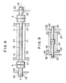
- Fig. 8 is a cross-sectional view, side elevational view showing a fourth embodiment of the present invention.
- the vibration assemblies A are respectively disposed at the opposite ends of the roller 20, and frictional contact between the frictional moving portion B of each vibration assembly A and the end portion of the axial bore 25 of the roller 20 is utilized to transform the oscillating motion of the frictional moving portions B into the rotation of the rotor 20.
- the small-diameter portions 1a of the respective vibration assemblies A are extended toward each other and joined together.
- a vibration driven motor having the above-described arrangement is driven so that vibration in the mode of, for example, three nodes is produced in each vibration assembly A, as in each of the embodiments described above.
- a shaft 30, which consists of the joined small-diameter portions 1a to serve as a substantially integrated vibration assembly, is vibrated with the loop of vibration located at the lengthwise central portion of the shaft 30 and the frictional moving portions B.
- the shaft 30 makes a circular motion of a predetermined radius about the axis l, whereas, with respect to the whole of the shaft 30, the shaft 30 makes a so-called skipping motion like a skipping rope which is being turned by two opposing persons.
- the loop of vibration produced at the lengthwise central portion 31 of the shaft 30 is utilized to cause the roller 20 to rotate by means of frictional contact between the central portion 31 and the inner periphery of the axial bore 25 of the roller 20.
- the frictional moving portions B of the respective vibration assemblies A are not utilized to rotate the rotor 20.
- driving is accomplished by the two vibration assemblies A, large torque for frictional driving can be obtained at the central portion 31 of the shaft 30, whereby the rotor 30 can be reliably rotated. If necessary, it is also possible to utilize oscillating motion generated at the frictional moving portions B.
- Fig. 9 is a schematic cross-sectional view showing a modification of the fourth embodiment according to the present invention.
- the two vibration members 1 and 1 are disposed so that their rear ends may face each other in the axial bore 25 of the rotor 20 and sandwich the piezoelectric disks 3 and 4 therebetween, thereby constituting one vibration assembly.
- the small-diameter portions 1a of the vibration members 1 and 1 are inserted into the respective axial bores 23 of the mounting member 22.
- the skipping motion with the loop of vibration formed at the sandwiching position of the piezoelectric disks is utilized to cause the rotor 20 to be rotated owing to frictional contact between the large- diameter portions 1b of the respective vibrating members 1 and 1 and the inner periphery of the axial bore 25 of the rotor 20.
- the large-diameter portions 1b of the respective vibration members 1 and 1 are accommodated in the rotor 20, space savings can be improved.
- Fig. 10 is a schematic cross-sectional view showing a fifth embodiment of the present invention.
- the rotor is supported by the bearing members 27.
- supporting shafts 41 and 42 extend from the respective ends of the roller 40, and the supporting shafts 41 and 42 are rotatably secured to a mounting member 45 by means of bearings 43 and 44, respectively.
- An axial bore 46 is formed to extend through a vibration assembly AA of a vibration driven motor A′ for driving the roller 40, and the supporting shaft 41 is inserted through the axial bore 46.
- the supporting shaft 41 and the axial bore 46 are axially disposed.
- the vibration assembly AA has a cylindrical vibration member 47 formed integrally with a small-diameter portion 1′a, and the cylindrical vibration member 47 has an engagement opening 48 of circular shape in cross section.
- the engagement opening 48 is engaged with the a connecting shaft 49 formed at one end of the roller 40.
- the cylindrical vibration member 47 is oscillated by the motion of the vibration driven motor A′ and the roller 40 is rotated by frictional contact with the connecting shaft 49.
- the roller 40 is not displaced in the radial direction during the driving of the vibration assembly AA and the connecting shaft 49 of the roller 40 is consistently maintained in frictional contact with the engagement opening 48 of the cylindrical vibration portion 47.
- a ring-shaped flange 50 is integrally formed on the portion of the vibration member 1′ at which the loop of vibration is formed.
- a plurality of brackets 51 extend from the mounting member 45, and resilient members 52 made of, for example, rubber, are respectively fitted with the brackets 51.
- the vibration assembly AA is retained between the brackets 51 so that the radial displacement of the vibration assembly AA can be absorbed by the intervening resilient members 52.
- the small-diameter shafts of the respective two vibration assemblies may be connected.
- the movable member if the movable member is driven by skipping motion with the loop of vibration located at the central portion of the connected small-diameter shafts, the movable member can be driven by large torque resulting from the sum of the torques of the two vibration assemblies, when compared to a conventional arrangement in which driving is performed by utilizing the first end of the vibration assembly.
- the large-diameter shaft of the vibration assembly is disposed in a hallow movable member so that the movable member is rotated by skipping motion
- the large-diameter shaft of the vibration assembly can be accommodated in the movable member. Accordingly, space savings can be improved.
- the two piezoelectric elements are utilized to generate vibrations in two directions, and a rotor is rotated by force resulting from a combination of the vibrations.
- three or more piezoelectric elements may be offset in position so that vibrations in a plurality of directions can be generated, and the rotor may be driven by force resulting from a combination of the vibrations.
- a vibration driven motor is arranged so that a vibration member and a movable member are moved relative to each other by utilizing non-travelling vibration.
- a supporting member for the motor is disposed at the position of the loop of the aforesaid vibration.
Landscapes
- General Electrical Machinery Utilizing Piezoelectricity, Electrostriction Or Magnetostriction (AREA)
- Buildings Adapted To Withstand Abnormal External Influences (AREA)
- Vibration Prevention Devices (AREA)
Abstract
Description
- The present invention relates generally to a motor for generating mechanical power without using electromagnetic force and, more particularly, to a vibration driven motor for rotating a driven member disposed coaxially to a vibration member by frictional driving obtained by utilizing the circular motion of a vibration member which is produced by a combination of vibrations due to expansion and contraction occurring in a plurality of axial directions.
- Conventional types of vibration driven motors are disclosed in, for example, Japanese Patent Laid-Open Nos. 62-141980, 63-214381 and 59-96881.
- As shown in Fig. 11, such a motor includes a
vibration member 100 made from a metallic round bar of horn shape whose root portion gradually decreases in outer diameter, apressure member 101 made from an annular metallic member having the same outer diameter as the large-diameter portion of thevibration member 100, and two annularmagnetostrictive plates vibration member 100 and thepressurc member 101. Thepressure member 101 is fixed to thevibration member 100 by abolt 104, and themagnetostrictive plates magnetostrictive plates magnetostrictive plates magnetostrictive plate 102 differs from that of the two divided electrodes of themagnetostrictive plate 103. Theseplates Electrode plates magnetostrictive plates electrode plate 105 is disposed in contact with the divided electrodes of themagnetostrictive plate 103 positioned on the second (or rear) side, while theelectrode plate 106 is disposed in contact with the common electrode of themagnetostrictive plate 102 positioned on the first (or front) side. The divided electrodes of the firstmagnetostrictive plate 102 and the common electrode of the secondmagnetostrictive plate 103 are disposed in contact with thevibration member 100 and the common electrode plate 107, respectively. - When AC voltages, which are equal in amplitude and frequency, are respectively applied across the first
magnetostrictive plate 102 and the secondmagnetostrictive plate 103 with a phase difference in time, vibration in which the vibration of themagnetostrictive plate 102 is combined with that of themagnetostrictive plate 103 is generated in the vibration member, whereby the extending end of the vibration member is caused to make a circular motion. - Fig. 12 shows a conventional vibration driven motor which utilizes such a vibration member as a driving source. The extending end of the vibration member is pressed in contact with one face of a
disk 108 to frictionally drive thedisk 108 by the circular motion of the extending end of the vibration member. Thus, rotational torque is transmitted from arotary shaft 109 fixed to the center of thedisk 108. - In the above-described conventional arrangement, the vibration member does not vibrate at its extending end only, but the entire vibration assembly constitutes one vibration system. It is, therefore, necessary to support the vibration member while minimizing the influence of vibration on the same.
- The vibration driven motor utilizing such a vibration member has another difficulty. For example, although the motor makes use of the motion of the extending end of the vibration member, it has been found from the experiments conducted by the present inventor that the rotational torque of the extending end of the vibration member is weak and sufficient driving torque cannot be applied to the disk which is a driven member.
- It is therefore an object of the present invention to provide a vibration driven motor capable of supporting a vibration member while minimizing the influence of vibration on the same.
- It is another object of the present invention to provide a vibration driven motor capable of applying sufficient torque to a vibration member and efficiently creating rotational torque, and of supporting the vibration member while minimizing the influence of vibration on the same.
- It is another object of the present invention to provide a vibration driven motor which has no fear of damaging a device in which it is incorporated.
- To achieve the above and other objects, according to the present invention, there is provided a vibration driven motor in which a vibration member and a movable member are moved relative to each other by utilizing non-travelling vibration, a supporting member for the motor being disposed at the position of the loop of the aforesaid vibration.
- The above and other objects, features and advantages of the present invention will be apparent from the following description of preferred embodiments of the invention with reference to the accompanying drawings.
-
- Fig. 1 is an exploded perspective view showing a first embodiment of a vibration driven motor according to the present invention;
- Fig. 2 is a waveform diagram of an AC source which is applied across a piezoelectric sheet;
- Fig. 3A is a side elevational view showing the oscillating motion of a vibration member for use in the first embodiment;
- Fig. 3B is a front elevational view showing the oscillating motion of the vibration member for use in the first embodiment;
- Fig. 4 is a cross-sectional side elevational view showing the manner in which the first embodiment of the vibration driven motor is mounted;
- Fig. 5 is a schematic view showing the manner in which the first embodiment of the vibration driven motor is driven;
- Fig. 6 is a cross-sectional, side elevational view showing a second embodiment of the vibration driven motor according to the present invention;
- Fig. 7 is a cross-sectional, side elevational view showing a third embodiment of the vibration driven motor according to the present invention;
- Fig. 8 is a cross-sectional, side elevational view showing a fourth embodiment of the vibration driven motor according to the present invention;
- Fig. 9 is a cross-sectional, side elevational view showing a modification of the fourth embodiment of the vibration driven motor according to the present invention;
- Fig. 10 is a cross-sectional view of, with a portion broken away, a fifth embodiment of the present invention;
- Fig. 11 is a schematic cross-sectional view showing a conventional vibration member; and
- Fig. 12 is a schematic perspective view showing a vibration driven motor utilizing the conventional vibration member.
- Preferred embodiments of the present invention will be described below in detail with reference to the accompanying drawings.
- Fig. 1 is an exploded perspective view showing a first embodiment of a vibration driven motor according to the present invention.
- A vibration assembly A includes a
vibration member 1 made from a rod-like metallic member. Thevibration member 1 is of a cylindrical configuration and includes a small-diameter portion 1a which constitutes a first end portion, a large-diameter portion 1c which constitutes a second end portion, and a horn-shaped portion 1c having a diameter which is gradually reduced along the axis toward the first end. The vibration assembly A also includes apressure member 2 made from a rod-like metallic member having an outer diameter which is the same as the diameter of the large-diameter portion 1b, andplates 3 and 4 each of which is made from a disk-shaped piezoelectric element having the same outer diameter as the large-diameter portion 1b. Thepiezoelectric plates 3 and 4 serve as electrical-to-mechanical energy transducers, respectively, and are disposed between thevibration member 1 and thepressure member 2 in such a manner that they sandwich an electrode plate 5. Thepressure member 2 is secured to thevibration member 1 by means abolt 6 so that thepiezoelectric plates 3 and 4 are secured in position between thevibration member 1 and thepressure member 2. The head of thebolt 6 is held against thepressure member 2 with an annular insulatingmember 7 interposed therebetween, while the shaft of thebolt 6 is held in non-contact with thepiezoelectric plates 3 and 4 and the electrode plate 5. - Each of the
piezoelectric plates 3 and 4 is polarized on one side in the direction of the thickness thereof so as to have two opposite electrodes, i.e., a positive electrode a and a negative electrode b. These electrode electrodes a and b are symmetrically formed with respect to an insulating portion d which crosses the central axis of the vibration assembly A. As illustrated, thepiezoelectric plates 3 and 4 are combined so that their directions of polarization differ from each other. Each of thepiezoelectric plates 3 and 4 further has a common electrode c shared by the positive and negative electrode electrodes a and b on the other side. The positive and negative electrode electrodes a and b are disposed out of phase with each other by an angle of 90 degrees with respect to the axis of the vibration assembly A, and the common electrode c of thepiezoelectric plate 3 and the polarized side of the piezoelectric plate 4 are disposed in contact with the respective sides of the electrode plate 5. The polarized side of thepiezoelectric plate 3, i.e., the positive electrode a and the negative electrode b, are maintained in contact with the first end face of thevibration member 1 serving as a conductor, while the common electrode c of the piezoelectric plate 4 is maintained in contact with the first end face of thepressure member 2. - An AC voltage V₁ is applied across the electrode plate 5 and the
vibration member 1, while an AC voltage V₂ is applied across the electrode plate 5 and thepressure member 2, whereby thepiezoelectric plate 3 and the piezoelectric plate 4 vibrate while expanding and contracting in the directions of their respective thicknesses. The resulting vibrations of therespective plates 3 and 5 in the direction of deflection are combined to vibrate the vibration assembly A. - The above-described vibration is a vibration which results from a combination of bending vibrations which are generated in different directions in a plane perpendicular to an axis ℓ of the vibration assembly A. Such a combined vibration may be called a non-traveling vibration which does not propagate along the axis of the vibration assembly A. In another aspect, the combined vibration is a vibration whose node and loop are not displaced along the axis of the rod-like vibration assembly A.
- As shown in Fig. 2, the AC voltage V₁ and the AC voltage V₂ are equal to each other in amplitude and frequency, but are 90° out of phase with each other. It follows, therefore, that the vibration assembly A is eccentrically displaced in response to the applied electrical signal, and makes a circular motion about its axis. Since the principle of the circular motion is known, explanation is omitted.
- If the opposite ends of the vibration assembly A are assumed to be free ends, respectively, the loop of the vibration is positioned at each of the opposite ends. Accordingly, because of the configuration of the vibration assembly A, the diameter of the circular motion of the
vibration member 1 at the first end of thevibration member 1 becomes even larger than the diameter of the second end of thepressure member 2, but torque caused by the circular motion at the first end of thevibration member 1 is made small. - In the first embodiment, the resonance frequency of the vibration assembly A is selected so that the loop of the vibration of the vibration assembly A is positioned at a first end B (hereinafter referred to as a "frictional moving portion") of the
horn portion 1c of thevibration member 1. Thepiezoelectric plates 3 and 4 are actuated at that resonance frequency. - More specifically, the vibration assembly A vibrates in the mode of three nodes or more with the loop of the vibration positioned at least at the opposite ends and frictional moving portion B of the vibration assembly A. Accordingly, the
vibration member 1 makes an oscillating motion in such a manner that thehorn portion 1c and the small-diameter portion 1a are oscillated about the axis ℓ, as shown in Figs. 3A and 3B, while a central point P at the first end of the small-diameter portion 1a is travelling around the circumference of a circle C, as shown in Fig. 3B. Arotor 8, which will be explained later, is rotated around the axis ℓ by utilizing the oscillating motion at the frictional moving portion B. The torque produced at the frictional moving portion B is even greater than that produced at the first end of the small-diameter portion 1a. - The
rotor 8 is engaged with the small-diameter portion 1a along the axis ℓ of the vibration assembly A, and a second end (hereinafter referred to as a "frictional contact portion") 8b of an inner-diameter portion 8a of therotor 8 is located at a position corresponding to the frictional moving portion B, whereby the second end of thefrictional contract portion 8b is engaged with thehorn portion 1c. As shown in Fig. 4, the inner diameter of the inner-diameter portion 8a of therotor 8 is selected to be slightly larger than the outer diameter of the small-diameter portion 1a of the vibration assembly A so as to accommodate the oscillating motion of the small-diameter portion 1a. The lengthwisecentral portion 8c of theinner diameter 8a is formed to have a far larger inner diameter so that it is prevented from coming into contact with the small-diameter portion 1a. - The
frictional contact portion 8b of therotor 8 is formed to become gradually wider toward the first end so as to match the outer configuration of the frictional moving portion B. Thefrictional contact portion 8b comes into line contact with the frictional moving portion B during the oscillating motion of thevibration member 1. - The
rotor 8 is urged in the direction of the arrows shown in Fig. 4 through a thrust bearing (not shown) by a spring or the like (not shown), thereby generating a predetermined frictional force at the area of contact between thefrictional contact portion 8b and the frictional moving portion B. The aforesaid thrust bearing allows therotor 8 to rotate about the axis thereof. - More specifically, when the vibration assembly A vibrates with the loop thereof positioned at the frictional moving portion B, that is, in the mode of three nodes, the
vibration member 1 makes the above-described oscillating motion about the axis ℓ as shown in Fig. 3. Accordingly, as shown in Fig. 5, the frictional moving portion B makes a circular motion in contact with thefrictional contact portion 8b of therotor 8 while drawing a locus of predetermined radius r with respect to the axis ℓ in the clockwise or counterclockwise direction. In Fig. 5, the outer diameter of the frictional moving portion B is shown as being much smaller than the inner diameter of thefrictional contact portion 8b of therotor 8 for the purpose of illustrating the manner in which the frictional moving portion B makes the circular motion in frictional contact with the inner periphery of thefrictional contact portion 8b of therotor 8. However, in practice, since the radius of the oscillating motion of the frictional moving portion B is extremely small, the gap between the frictional moving portion B and thefrictional contact portion 8b of therotor 8 is extremely small. - As described above, only the
vibration member 1 does not vibrate, but the vibration assembly A vibrates as a whole. Accordingly, when a vibration driven motor M including the above-described arrangement is to be mounted in a device such as a camera or a printer, it is necessary to consider a supporting method for the vibration assembly A and associated elements. - A method of supporting the vibration assembly A at the nodal position of vibration seems to be optimum because the vibration is small in amplitude. However, since the vibration assembly A makes an oscillating motion which starts on the nodal position of vibration, a plane perpendicular to the axis ℓ at the nodal position of the vibration is made to oscillate in the direction of the axis ℓ.
- For this reason, if a motor mounting flange extends from the position on the vibration assembly A which corresponds to the nodal position of vibration, that is, the outer periphery of the
vibration member 1 or thepressure member 2, that flange vibrates back and forth in the axial direction and a mounting portion for the aforesaid device such as a camera or a printer may be at worst broken due to vibrations. For this reason, it is inappropriate to support the vibration assembly A at the nodal position of vibration. - From examinations of the state of vibration of the vibration assembly A in various aspects, it is found that the position of the loop of vibration, which may seem inappropriate, is appropriate for a supporting position for the vibration assembly A.
- More specifically, although the amplitude of vibration is large at the position of the loop thereof, the vibration assembly is only displaced in the radial direction thereof, whereby the above-described fluctuating motion can be prevented. As can be seen from the structure of the vibration driven motor M, the loop position of vibration which serves as the supporting position is selected at a location axially rearwardly from the frictional moving portion B. Accordingly, if the vibration assembly A is to be vibrated in the mode of three nodes, the supporting position corresponds to the second end of the vibration assembly, while if the vibration assembly A is to be vibrated in the mode of four nodes, the supporting position is located at the second end of the vibration assembly A or between the second end of the vibration assembly A and the frictional moving portion B.
- The amplitude of vibration of the vibration assembly A is extremely small, and the amplitude of variation at the loop position serving as the supporting position is far smaller than the amplitude of the variation of the frictional moving portion B for actuating the
rotor 8. Accordingly, radial displacement can be substantially ignored, and the vibration assembly A can be stably mounted in a device by selecting the supporting position for the vibration assembly A as the loop position of vibration. - In Fig. 1, reference numeral 2aa denotes a supporting member which is provided at the loop position of the vibration of the vibration driven motor M. In a case where the second end of the vibration assembly A is selected as the supporting position as shown in Fig. 1, if that second end is secured to the securing member of a device or the like, the vibration assembly A assumes a vibration mode at the nodal positions which correspond to the opposite ends of the vibration assembly A. As a result, since the loop is not be formed at the frictional moving portion B, it is necessary to provide support so as to allow radial displacement. Although it is desirable that the position where the aforesaid supporting member is located accurately corresponds to the position of the loop, the former position is not limited only to the position of the loop and, for example, it may be located in the vicinity of the same.
- Fig. 6 is a cross-sectional, side elevational view showing, with a portion broken away, a second embodiment of the present invention.
- In the second embodiment, the vibration driven motor M, which includes a rotor different from that of the vibration driven motor M used in the first embodiment and which utilizes the same supporting structure as the vibration driven motor M, is used for a drive source for driving the platen roller of a printer. As shown in Fig. 6, the vibration driven motor M including the vibration assembly A and a
rotor 8A is accommodated in one end portion of aplaten roller 10. The vibration driven motor M also serves as a supporting shaft for one end of theplaten roller 10. - The vibration driven motor M has a securing
flange 2a formed at the second end of thepressure member 2 to support the second end of thepressure member 2 of the vibration assembly A. Theflange 2a is mounted on aprinter mounting frame 11 with a low-friction sheet 12 made from a low-friction material such as teflon or the like interposed therebetween. Theflange 2a has openings (not shown), and screws 13, whose shafts are smaller than the inner diameters of the respective openings, are inserted through the corresponding openings and threadedly fitted into the mountingframe 11. In this manner, the movement of the vibration driven motor M in the axial direction is restricted, but the expansion and contraction of theflange 2a in the radial direction is allowed. - The
platen roller 10 is rigidly fitted onto therotor 8A of the incorporated vibration driven motor M so that the rotational force of therotor 8A is directly transmitted to theplaten roller 10. A supportingshaft 14 is fixed to the other end of theplaten roller 10. The supportingshaft 14 is supported by aprinter mounting frame 16 for rotation about its axis and for movement along its axis. Aspring 17 is resiliently fitted onto the supportingshaft 14, and one end of thespring 17 is pressed against athrust bearing 18, while the other end is pressed against abearing 15. The spring force of thespring 17 acts to press therotor 8A against the vibration assembly A and enable theroller 10 to rotate about its axis. - Fig. 7 is a cross-sectional, side elevational view showing a third embodiment of the present invention.
- In the third embodiment, the vibration assemblies A is respectively disposed at the opposite ends of a
cylindrical rotor 20 so that therotor 20 is rotated by means of the two vibration assemblies A. A supportingshaft 21 extends rearwardly from the rear end of each of the vibration assemblies A to be fitted into a mountinghole 23 formed in a adjacent mountingmember 22. Aspring 24 is, as shown, resiliently fitted onto theshaft 21 so that thehorn portion 1c of the vibration assembly A is pressed against acorresponding end portion 26 of theaxial bore 25 of therotor 20. Theend portion 26 of theaxial bore 25 of therotor 20 is formed in a manner similar to that of thefriction contact portion 8b of the rotor shown in the first embodiment, and corresponds to the frictional moving portion B of the vibration assembly A. Therotor 20 is rotatably supported at the opposite ends of its outer periphery by bearingmembers 27, whereby therotor 20 is prevented from being shifted in the radial direction owing to the oscillating motion of the vibration assemblies A and the oscillating motion of the vibration assemblies A can be transformed into rotational force. - When the supporting
shafts 21 are fixed in the respective mountingholes 23, vibration mode may be changed as described above. In the third embodiment, to assure the degree of freedom of the supportingshafts 21 in the radial direction, the open end of each mountinghole 23 is defined by a taperedperiphery 28. - The
rotor 20 of the third embodiment may also be used as a platen roller for a printer such as that described in the second embodiment. - Fig. 8 is a cross-sectional view, side elevational view showing a fourth embodiment of the present invention.
- In the above-described third embodiment, the vibration assemblies A are respectively disposed at the opposite ends of the
roller 20, and frictional contact between the frictional moving portion B of each vibration assembly A and the end portion of theaxial bore 25 of theroller 20 is utilized to transform the oscillating motion of the frictional moving portions B into the rotation of therotor 20. In contrast, in the fourth embodiment, the small-diameter portions 1a of the respective vibration assemblies A are extended toward each other and joined together. - A vibration driven motor having the above-described arrangement is driven so that vibration in the mode of, for example, three nodes is produced in each vibration assembly A, as in each of the embodiments described above. In such driving, a
shaft 30, which consists of the joined small-diameter portions 1a to serve as a substantially integrated vibration assembly, is vibrated with the loop of vibration located at the lengthwise central portion of theshaft 30 and the frictional moving portions B. With respect to the lengthwise central portion of theshaft 30, theshaft 30 makes a circular motion of a predetermined radius about the axis ℓ, whereas, with respect to the whole of theshaft 30, theshaft 30 makes a so-called skipping motion like a skipping rope which is being turned by two opposing persons. - In the fourth embodiment, the loop of vibration produced at the lengthwise
central portion 31 of theshaft 30 is utilized to cause theroller 20 to rotate by means of frictional contact between thecentral portion 31 and the inner periphery of theaxial bore 25 of theroller 20. Unlike the above-described embodiment, in the fourth embodiment, the frictional moving portions B of the respective vibration assemblies A are not utilized to rotate therotor 20. However, since driving is accomplished by the two vibration assemblies A, large torque for frictional driving can be obtained at thecentral portion 31 of theshaft 30, whereby therotor 30 can be reliably rotated. If necessary, it is also possible to utilize oscillating motion generated at the frictional moving portions B. - Fig. 9 is a schematic cross-sectional view showing a modification of the fourth embodiment according to the present invention. The two
vibration members axial bore 25 of therotor 20 and sandwich thepiezoelectric disks 3 and 4 therebetween, thereby constituting one vibration assembly. The small-diameter portions 1a of thevibration members axial bores 23 of the mountingmember 22. - More specifically, the skipping motion with the loop of vibration formed at the sandwiching position of the piezoelectric disks is utilized to cause the
rotor 20 to be rotated owing to frictional contact between the large-diameter portions 1b of the respective vibratingmembers axial bore 25 of therotor 20. In this arrangement, since the large-diameter portions 1b of therespective vibration members rotor 20, space savings can be improved. - Fig. 10 is a schematic cross-sectional view showing a fifth embodiment of the present invention.
- In each of the above-described
embodiments members 27. However, in the fifth embodiment, supportingshafts roller 40, and the supportingshafts member 45 by means ofbearings - An
axial bore 46 is formed to extend through a vibration assembly AA of a vibration driven motor A′ for driving theroller 40, and the supportingshaft 41 is inserted through theaxial bore 46. The supportingshaft 41 and theaxial bore 46 are axially disposed. - The vibration assembly AA has a
cylindrical vibration member 47 formed integrally with a small-diameter portion 1′a, and thecylindrical vibration member 47 has anengagement opening 48 of circular shape in cross section. Theengagement opening 48 is engaged with the a connectingshaft 49 formed at one end of theroller 40. Thecylindrical vibration member 47 is oscillated by the motion of the vibration driven motor A′ and theroller 40 is rotated by frictional contact with the connectingshaft 49. During this time, since the supportingshafts roller 40 are supported by the correspondingbearings roller 40 is not displaced in the radial direction during the driving of the vibration assembly AA and the connectingshaft 49 of theroller 40 is consistently maintained in frictional contact with theengagement opening 48 of thecylindrical vibration portion 47. - As shown, a ring-shaped
flange 50 is integrally formed on the portion of thevibration member 1′ at which the loop of vibration is formed. A plurality ofbrackets 51 extend from the mountingmember 45, andresilient members 52 made of, for example, rubber, are respectively fitted with thebrackets 51. The vibration assembly AA is retained between thebrackets 51 so that the radial displacement of the vibration assembly AA can be absorbed by the interveningresilient members 52. - As is apparent from the foregoing, in accordance with the present invention, it is possible to stably support the vibration assembly by locating the loop of vibration of the vibration assembly at the position of the securing member of a device such as a printer.
- Since two vibration assemblies are used, it is possible to actuate a movable member by far larger torque.
- As described above, the small-diameter shafts of the respective two vibration assemblies may be connected. In this arrangement, if the movable member is driven by skipping motion with the loop of vibration located at the central portion of the connected small-diameter shafts, the movable member can be driven by large torque resulting from the sum of the torques of the two vibration assemblies, when compared to a conventional arrangement in which driving is performed by utilizing the first end of the vibration assembly.
- In the arrangement in which the large-diameter shaft of the vibration assembly is disposed in a hallow movable member so that the movable member is rotated by skipping motion, the large-diameter shaft of the vibration assembly can be accommodated in the movable member. Accordingly, space savings can be improved.
- In the arrangement in which both rotary shafts of a movable member are rotatably supported by a mounting member and a vibration assembly is inserted through the opening of one rotary shaft, the eccentric displacement or the like of the movable member can be prevented and rotational torque can be efficiently produced.
- In the above-described embodiment, the two piezoelectric elements are utilized to generate vibrations in two directions, and a rotor is rotated by force resulting from a combination of the vibrations. However, three or more piezoelectric elements may be offset in position so that vibrations in a plurality of directions can be generated, and the rotor may be driven by force resulting from a combination of the vibrations.
- While the present invention has been described with respect to what is presently considered to be the preferred embodiments, it is to be understood that the invention is not limited to the disclosed embodiments. To the contrary, the present invention is intended to cover various modifications and equivalent arrangements included within the spirit and scope of the appended claims. The scope of the following claims is to be accorded the broadest interpretation so as to encompass all such modifications and equivalent structures and functions.
- A vibration driven motor is arranged so that a vibration member and a movable member are moved relative to each other by utilizing non-travelling vibration. A supporting member for the motor is disposed at the position of the loop of the aforesaid vibration.
Claims (29)
Priority Applications (1)
| Application Number | Priority Date | Filing Date | Title |
|---|---|---|---|
| EP95105911A EP0665636B1 (en) | 1989-06-05 | 1990-06-05 | Vibration driven motor |
Applications Claiming Priority (2)
| Application Number | Priority Date | Filing Date | Title |
|---|---|---|---|
| JP1142339A JP2874762B2 (en) | 1989-06-05 | 1989-06-05 | Motor drive |
| JP142339/89 | 1989-06-05 |
Related Child Applications (2)
| Application Number | Title | Priority Date | Filing Date |
|---|---|---|---|
| EP95105911.2 Division-Into | 1990-06-05 | ||
| EP95105911A Division EP0665636B1 (en) | 1989-06-05 | 1990-06-05 | Vibration driven motor |
Publications (3)
| Publication Number | Publication Date |
|---|---|
| EP0401762A2 true EP0401762A2 (en) | 1990-12-12 |
| EP0401762A3 EP0401762A3 (en) | 1991-10-16 |
| EP0401762B1 EP0401762B1 (en) | 1996-03-20 |
Family
ID=15313059
Family Applications (2)
| Application Number | Title | Priority Date | Filing Date |
|---|---|---|---|
| EP90110633A Expired - Lifetime EP0401762B1 (en) | 1989-06-05 | 1990-06-05 | Vibration driven motor |
| EP95105911A Expired - Lifetime EP0665636B1 (en) | 1989-06-05 | 1990-06-05 | Vibration driven motor |
Family Applications After (1)
| Application Number | Title | Priority Date | Filing Date |
|---|---|---|---|
| EP95105911A Expired - Lifetime EP0665636B1 (en) | 1989-06-05 | 1990-06-05 | Vibration driven motor |
Country Status (5)
| Country | Link |
|---|---|
| US (2) | US5600196A (en) |
| EP (2) | EP0401762B1 (en) |
| JP (1) | JP2874762B2 (en) |
| KR (2) | KR0129769B1 (en) |
| DE (2) | DE69033630T2 (en) |
Cited By (8)
| Publication number | Priority date | Publication date | Assignee | Title |
|---|---|---|---|---|
| EP0406843A2 (en) * | 1989-07-05 | 1991-01-09 | Canon Kabushiki Kaisha | Vibration driven motor and system |
| EP0473423A2 (en) * | 1990-08-31 | 1992-03-04 | Canon Kabushiki Kaisha | Vibration driven motor |
| US5140215A (en) * | 1988-09-19 | 1992-08-18 | Brother Kogyo Kabushiki Kaisha | Vibrator and ultrasonic motor employing the same |
| US5231325A (en) * | 1990-12-14 | 1993-07-27 | Canon Kabushiki Kaisha | Vibration device for a vibration driven motor |
| US5656881A (en) * | 1990-04-05 | 1997-08-12 | Canon Kabushiki Kaisha | Vibration wave driven motor |
| CN101262184B (en) * | 2008-04-29 | 2010-07-14 | 哈尔滨工业大学 | Vertical bending layer energy converter round disk stator and ultrasonic electromotor using this stator |
| CN101262183B (en) * | 2008-04-29 | 2010-07-14 | 哈尔滨工业大学 | Vertical vibration layer energy converter round disk stator and ultrasonic electromotor using this stator |
| CN101388623B (en) * | 2008-07-07 | 2010-08-04 | 哈尔滨工业大学 | Longitudinal-shaking sandwich energy converter type cylinder shape dual rotor ultrasonic motor |
Families Citing this family (28)
| Publication number | Priority date | Publication date | Assignee | Title |
|---|---|---|---|---|
| DE69130751T2 (en) * | 1990-08-03 | 1999-07-01 | Canon Kk | Vibration driven motor |
| US5440190A (en) * | 1992-09-25 | 1995-08-08 | Olympus Optical Co., Ltd. | Ultrasonic motor |
| US6091179A (en) * | 1994-11-09 | 2000-07-18 | Nikon Corporation | Vibration actuator drive device and method of use |
| JPH08336287A (en) * | 1995-06-07 | 1996-12-17 | Nikon Corp | Ultrasonic actuator |
| JP3041242B2 (en) * | 1996-06-28 | 2000-05-15 | 株式会社アルテクス | Supporting device for resonator for ultrasonic vibration |
| JPH1084682A (en) * | 1996-09-09 | 1998-03-31 | Canon Inc | Vibration wave driving device and equipment having vibration wave driving device |
| US6107723A (en) * | 1996-12-26 | 2000-08-22 | Canon Kabushiki Kaisha | Vibrating type driving device |
| JP3397627B2 (en) * | 1997-04-08 | 2003-04-21 | キヤノン株式会社 | Vibration type driving device and device using the same |
| JPH1146487A (en) * | 1997-07-28 | 1999-02-16 | Canon Inc | Vibration actuator |
| JP3825890B2 (en) * | 1997-07-28 | 2006-09-27 | キヤノン株式会社 | Vibration actuator |
| JP4444395B2 (en) | 1999-06-15 | 2010-03-31 | キヤノン株式会社 | Vibration wave drive |
| JP4596610B2 (en) | 2000-05-31 | 2010-12-08 | キヤノン株式会社 | Vibration wave drive |
| US8087297B2 (en) * | 2004-03-04 | 2012-01-03 | Ludwiczak Damian R | Vibrating debris remover |
| US7084553B2 (en) * | 2004-03-04 | 2006-08-01 | Ludwiczak Damian R | Vibrating debris remover |
| US7770453B2 (en) * | 2004-03-04 | 2010-08-10 | Ludwiczak Damian R | Vibrating debris remover |
| JP4931183B2 (en) * | 2005-03-31 | 2012-05-16 | 富士フイルム株式会社 | Drive device |
| JP4809016B2 (en) * | 2005-08-12 | 2011-11-02 | 富士フイルム株式会社 | Actuator |
| JP2007117668A (en) * | 2005-10-31 | 2007-05-17 | Toshiba Corp | Ultrasonic probe and ultrasonographic apparatus |
| DE102008008581B4 (en) * | 2008-02-12 | 2018-12-06 | Bayerische Motoren Werke Aktiengesellschaft | lubricant pump |
| CN101262185B (en) * | 2008-04-29 | 2010-11-17 | 哈尔滨工业大学 | Bending layer energy converter round disk stator and ultrasonic electromotor using this stator |
| CN101262187B (en) * | 2008-04-29 | 2010-09-08 | 哈尔滨工业大学 | Bending vibration sandwich energy converter cylinder stator and ultrasonic electromotor using this stator |
| CN101388620B (en) * | 2008-07-07 | 2010-11-17 | 哈尔滨工业大学 | Sandwich type cylinder stator and ultrasonic motor using the same |
| CN103042281B (en) * | 2012-12-29 | 2016-01-27 | 苏州市职业大学 | Based on the ultrasonic edm Compound Machining oscillator of Hybrid transducer mode |
| BR112018009668B1 (en) | 2015-11-20 | 2021-07-27 | Colgate-Palmolive Company | SINGLE-PHASE ORAL CARE COMPOSITIONS AND THEIR MANUFACTURING METHOD |
| US10766624B2 (en) * | 2016-01-20 | 2020-09-08 | Honeywell International Inc. | Algorithm for efficiently breaking a material |
| CN105689248B (en) * | 2016-03-22 | 2018-06-26 | 许龙 | The orthogonal tubular energy converter of composite drive piezoelectricity of cross |
| CN106563634B (en) * | 2016-08-15 | 2019-03-22 | 哈尔滨理工大学 | A kind of design method of hollow exponential type ultrasonic amplitude transformer |
| CN109861583A (en) * | 2019-04-15 | 2019-06-07 | 太原科技大学 | A kind of superimposed type longitudinal vibration mode rotary piezo-electric motor |
Citations (2)
| Publication number | Priority date | Publication date | Assignee | Title |
|---|---|---|---|---|
| US4728843A (en) * | 1985-11-11 | 1988-03-01 | Taga Electric Co., Ltd. | Ultrasonic vibrator and drive control method thereof |
| EP0301429A2 (en) * | 1987-07-26 | 1989-02-01 | Honda Electronic Co., Ltd. | An ultrasonic driving device |
Family Cites Families (26)
| Publication number | Priority date | Publication date | Assignee | Title |
|---|---|---|---|---|
| SE436675B (en) * | 1975-08-12 | 1985-01-14 | Ki Politekhnichsky I Im 50 Let | ELECTRIC ENGINE OPERATED BY PIEZOELECTRIC FORCES |
| JPS6034433B2 (en) * | 1977-03-07 | 1985-08-08 | 株式会社豊田中央研究所 | ultrasonic transducer |
| JPS5899760A (en) * | 1981-12-09 | 1983-06-14 | Toshiba Corp | Probe device |
| CA1208269A (en) * | 1982-02-25 | 1986-07-22 | Toshiiku Sashida | Motor device utilizing ultrasonic oscillation |
| JPS5996881A (en) * | 1982-11-22 | 1984-06-04 | Toshio Sashita | Motor device utilizing supersonic vibration |
| JPS59178988A (en) * | 1983-03-29 | 1984-10-11 | Shinsei Kogyo:Kk | Stator of surface wave motor |
| DE3433768A1 (en) * | 1983-09-16 | 1985-04-18 | Hitachi Maxell, Ltd., Ibaraki, Osaka | Piezoelectric motor |
| US4663556A (en) * | 1984-01-11 | 1987-05-05 | Hitachi Maxell, Ltd. | Torsional mode ultrasonic vibrator |
| FR2571988B1 (en) * | 1984-10-23 | 1988-12-16 | Scp Biscornet | ULTRASONIC HEAD |
| US4697117A (en) * | 1985-11-27 | 1987-09-29 | Taga Electric Co., Ltd. | Rotary ultrasonic motor |
| JPS62141980A (en) * | 1985-12-16 | 1987-06-25 | Taga Denki Kk | Ultrasonic vibrator and drive controlling method thereof |
| EP0231940A3 (en) * | 1986-02-04 | 1990-01-17 | Siemens Aktiengesellschaft | Piezoelectric drive |
| JPS62239875A (en) * | 1986-04-09 | 1987-10-20 | Taga Electric Co Ltd | Drive control method for ultrasonic vibrator |
| US4812697A (en) * | 1986-04-09 | 1989-03-14 | Taga Electric Co., Ltd. | Ultrasonic vibrator and a method of controllingly driving same |
| US4882500A (en) * | 1986-06-04 | 1989-11-21 | Nippon Seimitsu Kogyo Kabushiki Kaisha | Method for converting standing wave vibrations into motion and standing wave motor therefor |
| US4868446A (en) * | 1987-01-22 | 1989-09-19 | Hitachi Maxell, Ltd. | Piezoelectric revolving resonator and ultrasonic motor |
| JP2595950B2 (en) * | 1987-01-27 | 1997-04-02 | 松下電器産業株式会社 | Ultrasonic motor drive |
| JPS63214381A (en) * | 1987-03-03 | 1988-09-07 | 多賀電気株式会社 | Ultrasonic vibrator and drive control method thereof |
| JP2559729B2 (en) * | 1987-03-26 | 1996-12-04 | キヤノン株式会社 | Vibration generator |
| JP2524346B2 (en) * | 1987-03-27 | 1996-08-14 | オリンパス光学工業株式会社 | Ultrasonic motor |
| JP2572988B2 (en) * | 1987-07-09 | 1997-01-16 | 日本特殊陶業株式会社 | Vertical / torsion-coupled bolt tightening vibrator |
| DE3852224T2 (en) * | 1987-07-14 | 1995-04-06 | Honda Electric Co | Ultrasonic driver arrangement. |
| JP2614635B2 (en) * | 1988-04-12 | 1997-05-28 | 日立マクセル株式会社 | Electrostrictive rotor and single-phase ultrasonic motor |
| US4965482A (en) * | 1988-06-17 | 1990-10-23 | Nec Corporation | Ultrasonic motor and method of adjusting the same |
| DE3920726A1 (en) * | 1988-06-29 | 1990-01-04 | Olympus Optical Co | Ultrasonic oscillator |
| JP2998978B2 (en) * | 1990-08-03 | 2000-01-17 | キヤノン株式会社 | Vibration wave device and drive device |
-
1989
- 1989-06-05 JP JP1142339A patent/JP2874762B2/en not_active Expired - Fee Related
-
1990
- 1990-06-05 DE DE69033630T patent/DE69033630T2/en not_active Expired - Fee Related
- 1990-06-05 DE DE69025984T patent/DE69025984T2/en not_active Expired - Fee Related
- 1990-06-05 EP EP90110633A patent/EP0401762B1/en not_active Expired - Lifetime
- 1990-06-05 EP EP95105911A patent/EP0665636B1/en not_active Expired - Lifetime
- 1990-06-05 KR KR1019900008293A patent/KR0129769B1/en not_active IP Right Cessation
-
1994
- 1994-03-25 KR KR1019940006054A patent/KR950013402B1/en not_active IP Right Cessation
-
1995
- 1995-04-03 US US08/415,673 patent/US5600196A/en not_active Expired - Lifetime
- 1995-04-06 US US08/417,843 patent/US5548175A/en not_active Expired - Lifetime
Patent Citations (2)
| Publication number | Priority date | Publication date | Assignee | Title |
|---|---|---|---|---|
| US4728843A (en) * | 1985-11-11 | 1988-03-01 | Taga Electric Co., Ltd. | Ultrasonic vibrator and drive control method thereof |
| EP0301429A2 (en) * | 1987-07-26 | 1989-02-01 | Honda Electronic Co., Ltd. | An ultrasonic driving device |
Cited By (12)
| Publication number | Priority date | Publication date | Assignee | Title |
|---|---|---|---|---|
| US5140215A (en) * | 1988-09-19 | 1992-08-18 | Brother Kogyo Kabushiki Kaisha | Vibrator and ultrasonic motor employing the same |
| EP0406843A2 (en) * | 1989-07-05 | 1991-01-09 | Canon Kabushiki Kaisha | Vibration driven motor and system |
| US5506462A (en) * | 1989-07-05 | 1996-04-09 | Canon Kabushiki Kaisha | Vibration motor |
| EP0406843B1 (en) * | 1989-07-05 | 1996-10-23 | Canon Kabushiki Kaisha | Vibration driven motor and system |
| US5656881A (en) * | 1990-04-05 | 1997-08-12 | Canon Kabushiki Kaisha | Vibration wave driven motor |
| EP0473423A2 (en) * | 1990-08-31 | 1992-03-04 | Canon Kabushiki Kaisha | Vibration driven motor |
| EP0473423A3 (en) * | 1990-08-31 | 1992-05-27 | Canon Kabushiki Kaisha | Vibration driven motor |
| US5274295A (en) * | 1990-08-31 | 1993-12-28 | Canon Kabushiki Kaisha | Vibration driven motor |
| US5231325A (en) * | 1990-12-14 | 1993-07-27 | Canon Kabushiki Kaisha | Vibration device for a vibration driven motor |
| CN101262184B (en) * | 2008-04-29 | 2010-07-14 | 哈尔滨工业大学 | Vertical bending layer energy converter round disk stator and ultrasonic electromotor using this stator |
| CN101262183B (en) * | 2008-04-29 | 2010-07-14 | 哈尔滨工业大学 | Vertical vibration layer energy converter round disk stator and ultrasonic electromotor using this stator |
| CN101388623B (en) * | 2008-07-07 | 2010-08-04 | 哈尔滨工业大学 | Longitudinal-shaking sandwich energy converter type cylinder shape dual rotor ultrasonic motor |
Also Published As
| Publication number | Publication date |
|---|---|
| US5600196A (en) | 1997-02-04 |
| KR950013402B1 (en) | 1995-11-08 |
| KR910002095A (en) | 1991-01-31 |
| EP0401762B1 (en) | 1996-03-20 |
| EP0665636B1 (en) | 2000-09-13 |
| EP0665636A1 (en) | 1995-08-02 |
| JP2874762B2 (en) | 1999-03-24 |
| DE69033630T2 (en) | 2001-05-03 |
| DE69025984T2 (en) | 1996-09-05 |
| JPH0311981A (en) | 1991-01-21 |
| DE69033630D1 (en) | 2000-10-19 |
| EP0401762A3 (en) | 1991-10-16 |
| KR0129769B1 (en) | 1998-04-09 |
| US5548175A (en) | 1996-08-20 |
| DE69025984D1 (en) | 1996-04-25 |
Similar Documents
| Publication | Publication Date | Title |
|---|---|---|
| US5600196A (en) | Vibration driven motor | |
| US5124611A (en) | Vibration motor | |
| US5656881A (en) | Vibration wave driven motor | |
| US5436522A (en) | Vibration drive actuator | |
| JPH0474952B2 (en) | ||
| US5821669A (en) | Vibration wave motor having piezoelectric pressure member | |
| JP3016577B2 (en) | Vibration wave device | |
| JP2001186781A (en) | Vibration actuator | |
| JP2925493B2 (en) | Vibration wave device | |
| JP2925492B2 (en) | Motor drive | |
| JP3113481B2 (en) | Piezo motor | |
| JPH0780793A (en) | Multi-degree-of-freedom actuator | |
| JPH08331875A (en) | Motor | |
| JP2996494B2 (en) | Vibration type motor device | |
| JPH04133678A (en) | Ultrasonic motor | |
| JP2000350481A (en) | Vibration wave-drive device and office equipment | |
| JPH0491678A (en) | Supersonic motor | |
| JPH08308266A (en) | Oscillation drive device | |
| JPH10248272A (en) | Vibration actuator | |
| JPH01136576A (en) | Supersonic motor | |
| JPH1169853A (en) | Ultrasonic motor | |
| JP2012070547A (en) | Rotary drive device | |
| JPH02188167A (en) | Ultrasonic motor |
Legal Events
| Date | Code | Title | Description |
|---|---|---|---|
| PUAI | Public reference made under article 153(3) epc to a published international application that has entered the european phase |
Free format text: ORIGINAL CODE: 0009012 |
|
| AK | Designated contracting states |
Kind code of ref document: A2 Designated state(s): DE FR GB IT |
|
| 17P | Request for examination filed |
Effective date: 19901221 |
|
| PUAL | Search report despatched |
Free format text: ORIGINAL CODE: 0009013 |
|
| AK | Designated contracting states |
Kind code of ref document: A3 Designated state(s): DE FR GB IT |
|
| 17Q | First examination report despatched |
Effective date: 19931116 |
|
| RIN1 | Information on inventor provided before grant (corrected) |
Inventor name: JUN, TAMAI |
|
| GRAA | (expected) grant |
Free format text: ORIGINAL CODE: 0009210 |
|
| AK | Designated contracting states |
Kind code of ref document: B1 Designated state(s): DE FR GB IT |
|
| PG25 | Lapsed in a contracting state [announced via postgrant information from national office to epo] |
Ref country code: IT Free format text: LAPSE BECAUSE OF FAILURE TO SUBMIT A TRANSLATION OF THE DESCRIPTION OR TO PAY THE FEE WITHIN THE PRESCRIBED TIME-LIMIT;WARNING: LAPSES OF ITALIAN PATENTS WITH EFFECTIVE DATE BEFORE 2007 MAY HAVE OCCURRED AT ANY TIME BEFORE 2007. THE CORRECT EFFECTIVE DATE MAY BE DIFFERENT FROM THE ONE RECORDED. Effective date: 19960320 |
|
| XX | Miscellaneous (additional remarks) |
Free format text: TEILANMELDUNG 95105911.2 EINGEREICHT AM 05/06/90. |
|
| REF | Corresponds to: |
Ref document number: 69025984 Country of ref document: DE Date of ref document: 19960425 |
|
| ET | Fr: translation filed | ||
| GRAH | Despatch of communication of intention to grant a patent |
Free format text: ORIGINAL CODE: EPIDOS IGRA |
|
| PLBE | No opposition filed within time limit |
Free format text: ORIGINAL CODE: 0009261 |
|
| STAA | Information on the status of an ep patent application or granted ep patent |
Free format text: STATUS: NO OPPOSITION FILED WITHIN TIME LIMIT |
|
| 26N | No opposition filed | ||
| REG | Reference to a national code |
Ref country code: GB Ref legal event code: IF02 |
|
| PGFP | Annual fee paid to national office [announced via postgrant information from national office to epo] |
Ref country code: DE Payment date: 20080630 Year of fee payment: 19 |
|
| PGFP | Annual fee paid to national office [announced via postgrant information from national office to epo] |
Ref country code: FR Payment date: 20080625 Year of fee payment: 19 |
|
| PGFP | Annual fee paid to national office [announced via postgrant information from national office to epo] |
Ref country code: GB Payment date: 20080627 Year of fee payment: 19 |
|
| GBPC | Gb: european patent ceased through non-payment of renewal fee |
Effective date: 20090605 |
|
| REG | Reference to a national code |
Ref country code: FR Ref legal event code: ST Effective date: 20100226 |
|
| PG25 | Lapsed in a contracting state [announced via postgrant information from national office to epo] |
Ref country code: FR Free format text: LAPSE BECAUSE OF NON-PAYMENT OF DUE FEES Effective date: 20090630 |
|
| PG25 | Lapsed in a contracting state [announced via postgrant information from national office to epo] |
Ref country code: GB Free format text: LAPSE BECAUSE OF NON-PAYMENT OF DUE FEES Effective date: 20090605 |
|
| PG25 | Lapsed in a contracting state [announced via postgrant information from national office to epo] |
Ref country code: DE Free format text: LAPSE BECAUSE OF NON-PAYMENT OF DUE FEES Effective date: 20100101 |