EP0401469A1 - Dispositif de tri - Google Patents
Dispositif de tri Download PDFInfo
- Publication number
- EP0401469A1 EP0401469A1 EP90103629A EP90103629A EP0401469A1 EP 0401469 A1 EP0401469 A1 EP 0401469A1 EP 90103629 A EP90103629 A EP 90103629A EP 90103629 A EP90103629 A EP 90103629A EP 0401469 A1 EP0401469 A1 EP 0401469A1
- Authority
- EP
- European Patent Office
- Prior art keywords
- arm
- push
- sorting device
- main conveyor
- swivel
- Prior art date
- Legal status (The legal status is an assumption and is not a legal conclusion. Google has not performed a legal analysis and makes no representation as to the accuracy of the status listed.)
- Withdrawn
Links
Images


Classifications
-
- B—PERFORMING OPERATIONS; TRANSPORTING
- B65—CONVEYING; PACKING; STORING; HANDLING THIN OR FILAMENTARY MATERIAL
- B65G—TRANSPORT OR STORAGE DEVICES, e.g. CONVEYORS FOR LOADING OR TIPPING, SHOP CONVEYOR SYSTEMS OR PNEUMATIC TUBE CONVEYORS
- B65G47/00—Article or material-handling devices associated with conveyors; Methods employing such devices
- B65G47/74—Feeding, transfer, or discharging devices of particular kinds or types
- B65G47/76—Fixed or adjustable ploughs or transverse scrapers
- B65G47/766—Adjustable ploughs or transverse scrapers
-
- B—PERFORMING OPERATIONS; TRANSPORTING
- B65—CONVEYING; PACKING; STORING; HANDLING THIN OR FILAMENTARY MATERIAL
- B65G—TRANSPORT OR STORAGE DEVICES, e.g. CONVEYORS FOR LOADING OR TIPPING, SHOP CONVEYOR SYSTEMS OR PNEUMATIC TUBE CONVEYORS
- B65G47/00—Article or material-handling devices associated with conveyors; Methods employing such devices
- B65G47/74—Feeding, transfer, or discharging devices of particular kinds or types
- B65G47/82—Rotary or reciprocating members for direct action on articles or materials, e.g. pushers, rakes, shovels
Definitions
- the invention relates to a sorting device with at least one motor-driven main conveyor, on which piece goods are conveyed, the main conveyor being assigned at least one motor-driven discharge or cross conveyor which conveys the piece goods to be sorted out by means of a motor-operated swivel pusher, the swivel pusher being a swivel arm and has a push-off arm and the push-off arm is arranged so that it can move back and forth above the surface of the main conveyor and these arms are at an acute angle to one another, in the rest position the push-off arm approximately parallel to the conveying direction of the main conveyor at the level of the piece goods outside the transport area of the piece goods above the Main conveyor is positioned, wherein the push-off arm can be driven via an eccentric drive and the sorting device is arranged on one side of the main conveyor so as to be pivotable t is, the point of application of the eccentric being possibly adjustable.
- Such a sorting device forms the subject of DE-OS 37 37 543, which goes back to the applicant, and of EP-OS 0 314 881 with the same content.
- a sorting device with at least one motor-driven main conveyor on which piece goods are conveyed up, with the main conveyor being assigned at least one motor-driven discharge or cross conveyor which conveys the piece goods to be sorted out by means of a motor-operated swivel pusher
- the Swivel pusher consists of a swivel arm and a push-off arm, and this arm, viewed in the direction of the swivel axis of the swivel pusher, is oriented at an angle - preferably an acute angle - to one another and is spaced in the direction of the swivel axis and arranged in different planes and integrally rigidly connected to one another, and the Swivel axis is arranged at the free end of the swivel arm, with the push-off arm in the rest position approximately parallel to the conveying direction of the main conveyor at the level of the piece goods outside the transport area of the piece goods he on the Main conveyor is
- the invention has for its object to improve a sorting device of the generic type in such a way that different sorting and possibly also very flat piece goods can be sorted out in any sequence from the main conveyor belt to a cross conveyor with different sorting capacities in the outer dimensions.
- the contact surface of the push-off arm is approximately parallel to the main conveying direction of the piece goods on the main conveyor.
- the pivot arrangement of the swivel arm and the drive arm depending on the arm lengths allow the push arm in its maximum swivel position at an acute angle of z. B. 30 ° to the direction of conveyance on the main conveyor.
- the special shape of the push-off arm enables the piece goods to be pushed off relatively softly. Large or long piece goods can better turn further to 90 ° because there is more free space available.
- this embodiment of the sorting device according to the invention allows a smaller safety distance between the piece goods. B. for the package sorting device in main post offices is of great advantage.
- the swiveling movement takes place relatively slowly in the first half of the eccentric movement, so that the piece goods are only exposed to slight stresses.
- the general cargo is accelerated more and rotated more.
- this rotary movement sorts the piece goods approximately 90 ° after a relatively short swiveling movement.
- the sorting device By designing the sorting device with a swivel arm and a push-off arm, there is an additional relative movement in the main conveying direction, but only a slight relative movement between piece goods and contact surface of the push-off arm.
- Another advantage of the invention is that the push-off arm sets the piece goods in a rotational movement and therefore the pivoting angle to the main conveying direction can be kept relatively small, as a result of which its mean effective moment of inertia is considerably smaller than that of the known construction.
- the sorting device according to the invention allows shorter pivoting times of the push-off arm with the same drive power.
- sorting services of e.g. B. safely sort out 6,000 units per hour in combination with a belt or steel belt with a take-off roller and / or take-off conveyor.
- This is of great advantage e.g. B. in the package promotion in large post offices, in which not only these large numbers of packages are incurred, but the packages, d. H. the piece goods, also have very different dimensions on the outside.
- the space below the upper run z. B. be used for the return transport of piece goods.
- the drive arm usually differs only in its different length and an additional articulation point on the crank rod.
- the exact guidance of the push-off arm enables the sorting out of very flat piece goods of e.g. B. only 5 mm in height, measured orthogonally from the surface of the main conveyor.
- Preferred basic position of the push arm can, for. B. 0.5 to 50, preferably 25 mm above the outer edge of the conveyor belt of the main conveyor, since jamming or the like is then impossible.
- the reference numeral 1 denotes a main conveyor 2 which is motor-driven in the direction of the arrow and which, in the embodiments shown, is designed as a belt conveyor, but can also consist of driven roller conveyors.
- the upper run is designated in FIGS. 3 and 4 with the reference number 2a and the lower run with the reference number 2b.
- piece goods 3 lie close together in an irregular sequence - taking into account a small safety distance.
- the relationships are shown to scale in the drawing.
- different boxes for medicines can be arranged on the upper run 2a.
- a plurality of sorting devices 4 which are only arranged schematically, are arranged laterally, the construction of which is described in detail below.
- transverse conveyors 5, 6, 7 are arranged, onto which the piece goods 3 which have been sorted out are transported in the direction of the arrows 8, 9 or 10.
- the cross conveyor 5 has a slide and a cylindrical, motor-driven take-off roller 11, while the cross conveyor 6 also has a slide and a conical, motor-driven take-off roller 12.
- the cross conveyor 7 has a motor-driven discharge conveyor 13, which can either be designed as a belt conveyor or the like. Another possible embodiment is not shown tion form of the cross conveyor 7, consisting of a driven take-off roller with a belt conveyor arranged subsequently.
- cross conveyors it is of course also possible to arrange more than three cross conveyors over the length of a main conveyor 2, as it is also possible to assign only one such cross conveyor to the main conveyor instead of several cross conveyors, or else to arrange 2 sorting devices and / or cross conveyors on both sides of the main conveyor.
- the number of cross conveyors depends on the operating conditions.
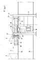
- the sorting device 4 has a push-off arm 14, which in cross section consists of a U-profile (FIG. 3), the U-legs of which extend in horizontal planes and the web of which is arranged orthogonally to the surface of the upper strand 2a (FIG. 3). This results in a relatively large contact surface for the piece goods 3, so that they are not damaged.
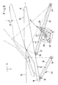
- Reference number 15 denotes a swivel arm, which is only indicated schematically in FIG. 1.
- the swivel arm 15 is arranged to be pivotable about a vertically arranged axis 16 in the horizontal plane by a limited amount, that is to say in the X or Y direction.
- the pivot axis 16 is fixed in a frame 17 with respect to the main conveyor 2.
- the frame 17 stands on the floor next to the main conveyor 2 and serves to arrange and store parts of the sorting device 4, which will be described below.
- the pivot axis 16 thus also runs orthogonally to the surface of the upper run 2a of the main conveyor 2.
- the pivot axis 16 is arranged with its longitudinal axis parallel to a further pivot axis 18, with which the pivot arm 15 is pivotally arranged on a bearing projection 19 of the push-off arm 14.
- the pivot axis 18 thus also runs vertically.
- a further bearing projection 20 is arranged at a distance from the bearing projection 19, in which a pivot axis 21 is arranged with its longitudinal axis parallel to the axes 16 and 18.
- the pivot axis 21 is used for the pivotable articulation of a drive arm 22, which is shown in the th embodiments is about twice as long as the swivel arm 15.
- the drive arm 22 is also arranged to be pivotable about a swivel axis 23 in the X or Y direction, that is to say in a horizontal plane parallel to the swivel arm 15.
- the pivot axis 23 runs parallel to the longitudinal axes of the pivot axes 16, 18 and 21, thus also vertically and is likewise fixed in the frame 17, ie immovable, in particular immovable in relation to the main conveyor 2.
- angles ⁇ and ⁇ are not the same, but are each at an acute angle, so that the swivel arm 15 and the drive arm 22 do not run parallel to one another.
- the push-off arm 14 has a contact surface 24 which runs parallel or essentially parallel to the outer longitudinal boundary of the upper run 2a of the main conveyor 2. As can be seen from FIG. 5, in the starting position, the push-off arm 14 engages with its contact surface 24 to a certain extent with the lateral boundary 25 of the main conveyor 2, so that jammed goods 3 un is possible.
- the distance between the lower edge of the push-off arm 14 and the upper edge of the upper run 2a of the main conveyor 2 can, for. B. 5 mm.
- the push-off arm 14 sweeps parallel, ie in the horizontal plane, the surface of the upper strand 2a.
- Fig. 5 shows with a solid line the starting position during the pushing-off process of the push-off arm 14 and with dash-dotted lines different angular positions. The same applies to the illustration in FIG. 2, in which the upper, dash-dotted position of the push-off arm 14 illustrates the maximum pivoting position thereof (seen in the plane of the drawing).
- the drive arm 22 is connected via a crank rod 26 to an eccentric drive 27, which is driven by a powerful drive motor 28 from e.g. B. 1.1 KW drive power is driven.
- a powerful drive motor 28 from e.g. B. 1.1 KW drive power is driven.
- 30 designates a pivot point of the eccentric drive 27 which moves in the Z direction.
- the preferred drive direction of the eccentric drive 27 is indicated by the arrow direction Z (FIG. 5).
- the drive motor 28 is arranged below the swivel arm 15, the drive arm 22 and the push-off arm 14.
- the push-off arm 14, swivel arm 15 and drive arm 22 thus move synchronously in the horizontal plane, the push-off arm 14 changing its angle of attack with respect to the conveying direction 1 and thus also with respect to the incoming conveyed goods 3 (FIGS. 2 and 5).
- the eccentric 27 can be adjusted and locked in order to change the forward and return angle and thus to change the pushing-off speed and the return stroke.
- the mode of action is as follows: Allocated piece goods 3 of various sizes and dimensions are transported in the direction of arrow 1 on the main conveyor 2 at a minimum distance. Depending on the target, the piece goods 3 via leading edge pulse or the like on the cross conveyors 5, 6 and 7 or on only one of these conveyors, for. B. pushed onto the cross conveyor 5.
- the push-off arm 14 of the sorting device 4 is parallel or approximately parallel to the conveying direction 1 with its contact surface 24 and is arranged directly on the outer edge 25 above it in a plane parallel to this or overlaps this edge 25.
- the drive motor 28 rotates the eccentric drive 27 in the direction Z (FIG. 5) and the eccentric moves over the crank rod 26 against the articulation point 29 and thus moves the drive arm 22 horizontally in the direction of the belt center.
- the swivel arm 15 is also moved via the connection through the push-off arm 14. Due to the different swivel arm length of about 1: 2, the push-off arm 14 moves in the first half of the forward movement approximately parallel against the piece goods 3 in the direction of the cross conveyor, e.g. B. 5.
- the piece goods 3 After the piece goods have been supported against the large contact surface 24, it is accelerated more strongly and set into a rotational movement, so that, despite the small pivoting angle ⁇ , the piece goods 3 are removed from the higher take-off roller, e.g. B. 11 - possibly over a friction lining, not shown - is taken over. From the resulting movement, the piece goods 3 is rotated by 90 ° and by the cross conveyor, for. B. 5, forwarded.
- the higher take-off roller e.g. B. 11 - possibly over a friction lining, not shown - is taken over. From the resulting movement, the piece goods 3 is rotated by 90 ° and by the cross conveyor, for. B. 5, forwarded.
- the return stroke movement takes place in a shorter time than the preliminary stroke, so that the safety distance between the piece goods 3 can be kept relatively small in connection with the special shape of the push-off arm 14, and z. B. only needs to be 50 cm.
- the next general cargo may already enter the area of the sorting device 4.
- the contact surface 24 of the push-off arm 14 is approximately parallel to the main conveying direction 1 of the main conveyor 2 in the starting position.
- the pivot point arrangement of the swivel arm 15 in dependence on the different effective arm lengths of the swivel arm 15 and the drive arm 22 enable the push arm 14 in its maximum swivel position under z. B. 30 ° to the conveying direction 1.
- the special shape of the push-off arm 14 enables the piece goods 3 to be pushed off relatively softly. Large or long piece goods 3 can better turn further to 90 ° since there is more free space.
- the shape of the push arm 14 allows a smaller safety distance between piece goods 3, z. B. packages.
- the forward pivoting movement takes place relatively slowly in the first half of the eccentric movement, so that the piece goods 3 are exposed to only slight stresses.
- the general cargo 3 is accelerated more and additionally rotated more.
- the piece goods 3 are sorted by approximately 90 ° after a relatively short swiveling movement by means of this rotational movement.
- Another advantage of the invention which results from the fact that the push-off arm 14 sets the piece goods 3 in a rotational movement and therefore the pivoting angle to the main conveying direction 1 can be kept relatively small, is that its mean effective moment of inertia is significantly smaller than that of known designs . Shorter pivoting times of the push-off arm 14 are thereby possible.
- z. B 5,000 to 9,000 piece goods 3 per hour, preferably about 5,000 to 6,000 piece goods 3 per hour, in combination with belt or steel belts with take-off roller 11 and / or take-off conveyor.
- the basic position of the push-off arm 14 can be adapted to the relevant conditions.
- the preferred basic position of the push-off arm 14 in the illustrated embodiment is approximately 25 mm above the outer edge 25 (FIG. 5) of the main conveyor 2.
Landscapes
- Engineering & Computer Science (AREA)
- Mechanical Engineering (AREA)
- Discharge Of Articles From Conveyors (AREA)
- Branching, Merging, And Special Transfer Between Conveyors (AREA)
Applications Claiming Priority (2)
| Application Number | Priority Date | Filing Date | Title |
|---|---|---|---|
| DE19893918196 DE3918196C1 (fr) | 1989-06-03 | 1989-06-03 | |
| DE3918196 | 1989-06-03 |
Publications (1)
| Publication Number | Publication Date |
|---|---|
| EP0401469A1 true EP0401469A1 (fr) | 1990-12-12 |
Family
ID=6382036
Family Applications (1)
| Application Number | Title | Priority Date | Filing Date |
|---|---|---|---|
| EP90103629A Withdrawn EP0401469A1 (fr) | 1989-06-03 | 1990-02-24 | Dispositif de tri |
Country Status (4)
| Country | Link |
|---|---|
| EP (1) | EP0401469A1 (fr) |
| DD (1) | DD294675A5 (fr) |
| DE (1) | DE3918196C1 (fr) |
| FI (1) | FI902736A0 (fr) |
Cited By (4)
| Publication number | Priority date | Publication date | Assignee | Title |
|---|---|---|---|---|
| DE102004037976A1 (de) * | 2004-08-05 | 2006-03-16 | Comsort Gmbh | Vorrichtung zum Fördern und Sortieren von Stückgut |
| EP2492220A1 (fr) * | 2011-02-22 | 2012-08-29 | ELSAG DATAMAT S.p.A. | Dispositif pour dévier des objets, en particulier des bagages, transportés par une bande convoyeuse |
| CN103950714A (zh) * | 2014-01-13 | 2014-07-30 | 上海三载机械制造有限公司 | 一种能自动铺料的输送系统 |
| CN106542319A (zh) * | 2017-01-20 | 2017-03-29 | 金华明正科技有限公司 | 一种摆臂式产线输送换向装置 |
Families Citing this family (2)
| Publication number | Priority date | Publication date | Assignee | Title |
|---|---|---|---|---|
| DE102005057866B4 (de) * | 2005-12-02 | 2019-01-31 | R. Weiss Verpackungstechnik Gmbh & Co. Kg | Abgabeeinrichtung für Lebensmittel |
| CH707448A1 (de) | 2013-01-15 | 2014-07-15 | Ferag Ag | Förderanlage. |
Citations (1)
| Publication number | Priority date | Publication date | Assignee | Title |
|---|---|---|---|---|
| DE2242457B2 (de) * | 1971-10-21 | 1975-10-23 | Daverio Ag | Abschiebeweiche an einer Transportbahn für auszusortierende Gegenstände, insbesondere Postpakete |
Family Cites Families (2)
| Publication number | Priority date | Publication date | Assignee | Title |
|---|---|---|---|---|
| JPS52141958A (en) * | 1976-05-21 | 1977-11-26 | Nippon Sandobitsuku Kk | Apparatus for pushing goods out of belt conveyor |
| DE3737543A1 (de) * | 1987-11-05 | 1989-05-24 | Arnold L & C | Aussortiervorrichtung fuer stueckgueter |
-
1989
- 1989-06-03 DE DE19893918196 patent/DE3918196C1/de not_active Expired - Fee Related
-
1990
- 1990-02-24 EP EP90103629A patent/EP0401469A1/fr not_active Withdrawn
- 1990-05-28 DD DD34104690A patent/DD294675A5/de not_active IP Right Cessation
- 1990-06-01 FI FI902736A patent/FI902736A0/fi not_active IP Right Cessation
Patent Citations (1)
| Publication number | Priority date | Publication date | Assignee | Title |
|---|---|---|---|---|
| DE2242457B2 (de) * | 1971-10-21 | 1975-10-23 | Daverio Ag | Abschiebeweiche an einer Transportbahn für auszusortierende Gegenstände, insbesondere Postpakete |
Cited By (6)
| Publication number | Priority date | Publication date | Assignee | Title |
|---|---|---|---|---|
| DE102004037976A1 (de) * | 2004-08-05 | 2006-03-16 | Comsort Gmbh | Vorrichtung zum Fördern und Sortieren von Stückgut |
| DE102004037976B4 (de) * | 2004-08-05 | 2008-05-29 | Comsort Gmbh | Vorrichtung zum Fördern und Sortieren von Stückgut |
| EP2492220A1 (fr) * | 2011-02-22 | 2012-08-29 | ELSAG DATAMAT S.p.A. | Dispositif pour dévier des objets, en particulier des bagages, transportés par une bande convoyeuse |
| CN103950714A (zh) * | 2014-01-13 | 2014-07-30 | 上海三载机械制造有限公司 | 一种能自动铺料的输送系统 |
| CN106542319A (zh) * | 2017-01-20 | 2017-03-29 | 金华明正科技有限公司 | 一种摆臂式产线输送换向装置 |
| CN106542319B (zh) * | 2017-01-20 | 2019-05-03 | 兰溪华能输送设备制造有限公司 | 一种摆臂式产线输送换向装置 |
Also Published As
| Publication number | Publication date |
|---|---|
| FI902736A0 (fi) | 1990-06-01 |
| DE3918196C1 (fr) | 1990-08-23 |
| DD294675A5 (de) | 1991-10-10 |
Similar Documents
| Publication | Publication Date | Title |
|---|---|---|
| EP0286080B1 (fr) | Dispositif pour diriger le transfert d'objets | |
| EP0564901B1 (fr) | Dispositif d'avance pour tÔle | |
| DE3215744A1 (de) | Sortiervorrichtung fuer stueckgut | |
| EP0597354B1 (fr) | Dispositif de transport pour récipients | |
| EP0595767A1 (fr) | Dispositf pour tourner des objets plats | |
| DD140132A5 (de) | Vorrichtung zum beschicken einer packmaschine mit suesswaren | |
| DE3918196C1 (fr) | ||
| EP0501923A1 (fr) | Dispositif pour le retournement d'objets plats par exemple des papiers-valeur | |
| EP0314881A1 (fr) | Dispositif de triage pour marchandises | |
| DE1951598B2 (de) | Ausweichspur für eine Arbeitsvorrichtung enthaltende Fertigungsstraßen | |
| CH670809A5 (fr) | ||
| DE3829305C2 (fr) | ||
| DE19516403C2 (de) | Vorrichtung zum Überführen von Gegenständen, insbesondere Flaschen | |
| EP0423519B1 (fr) | Transporteur pour le transfert de pots de filature et utilisation du transporteur | |
| DE2945213A1 (de) | Foerderbahn mit eingabe- und abwerfvorrichtungen | |
| DE3814195C2 (fr) | ||
| DE10126876B4 (de) | Verfahren und Vorrichtung zum Sortieren von Stückgütern | |
| DE2932286A1 (de) | Vorrichtung zum stapelfoermigen einfuellen von flaechengebilden, insbesondere diarahmen, in einen behaelter | |
| DE2304331A1 (de) | Foerdersystem | |
| DE2062889A1 (de) | Ausrichte- und Aufstellvorrichtung für Körper | |
| DE3936874C2 (de) | Abgabevorrichtung für Behälter, insbesondere für Flaschen | |
| DE4212833A1 (de) | Vorrichtung zum trennen duenner und flacher gegenstaende, wie z. b. kartonzuschnitte, die aufeinanderfolgend in kontinuierlicher reihe auf wenigstens einer transportvorrichtung bewegt werden | |
| DE4202244A1 (de) | Sortiereinrichtung | |
| DE3140021A1 (de) | Einrichtung zur bildung und angabe von paeckchen aus mehreren, flaechigen einzelerzeugnissen aus papier, zellstoffwatte od. dgl. | |
| DE3118440C2 (de) | Anordnung zum Klassieren von stabartigen Elementen, insbesondere Parkettstäben |
Legal Events
| Date | Code | Title | Description |
|---|---|---|---|
| PUAI | Public reference made under article 153(3) epc to a published international application that has entered the european phase |
Free format text: ORIGINAL CODE: 0009012 |
|
| 17P | Request for examination filed |
Effective date: 19900306 |
|
| AK | Designated contracting states |
Kind code of ref document: A1 Designated state(s): AT BE CH DK ES FR GB GR IT LI LU NL SE |
|
| RAP1 | Party data changed (applicant data changed or rights of an application transferred) |
Owner name: L. & C. ARNOLD AG |
|
| 17Q | First examination report despatched |
Effective date: 19920203 |
|
| STAA | Information on the status of an ep patent application or granted ep patent |
Free format text: STATUS: THE APPLICATION IS DEEMED TO BE WITHDRAWN |
|
| 18D | Application deemed to be withdrawn |
Effective date: 19921013 |