EP0401220B1 - Rotationskolben-druckluftmotor - Google Patents
Rotationskolben-druckluftmotor Download PDFInfo
- Publication number
- EP0401220B1 EP0401220B1 EP88909729A EP88909729A EP0401220B1 EP 0401220 B1 EP0401220 B1 EP 0401220B1 EP 88909729 A EP88909729 A EP 88909729A EP 88909729 A EP88909729 A EP 88909729A EP 0401220 B1 EP0401220 B1 EP 0401220B1
- Authority
- EP
- European Patent Office
- Prior art keywords
- compressed air
- housing
- ignition spark
- supply line
- motor according
- Prior art date
- Legal status (The legal status is an assumption and is not a legal conclusion. Google has not performed a legal analysis and makes no representation as to the accuracy of the status listed.)
- Expired - Lifetime
Links
- 230000004888 barrier function Effects 0.000 claims abstract description 46
- 239000002184 metal Substances 0.000 claims abstract description 9
- 239000008187 granular material Substances 0.000 claims description 2
- 239000011224 oxide ceramic Substances 0.000 claims description 2
- 229910052574 oxide ceramic Inorganic materials 0.000 claims description 2
- 239000000843 powder Substances 0.000 claims description 2
- 229910001220 stainless steel Inorganic materials 0.000 claims description 2
- 239000010935 stainless steel Substances 0.000 claims description 2
- 238000004880 explosion Methods 0.000 abstract description 6
- 230000015556 catabolic process Effects 0.000 description 42
- 239000002360 explosive Substances 0.000 description 5
- 230000008878 coupling Effects 0.000 description 2
- 238000010168 coupling process Methods 0.000 description 2
- 238000005859 coupling reaction Methods 0.000 description 2
- 239000000203 mixture Substances 0.000 description 2
- 241000218645 Cedrus Species 0.000 description 1
- 230000006835 compression Effects 0.000 description 1
- 238000007906 compression Methods 0.000 description 1
- 230000005611 electricity Effects 0.000 description 1
- 238000005538 encapsulation Methods 0.000 description 1
- 239000000835 fiber Substances 0.000 description 1
- 238000010304 firing Methods 0.000 description 1
- 238000009434 installation Methods 0.000 description 1
- 239000011148 porous material Substances 0.000 description 1
- 230000003068 static effect Effects 0.000 description 1
Images

Classifications
-
- F—MECHANICAL ENGINEERING; LIGHTING; HEATING; WEAPONS; BLASTING
- F01—MACHINES OR ENGINES IN GENERAL; ENGINE PLANTS IN GENERAL; STEAM ENGINES
- F01C—ROTARY-PISTON OR OSCILLATING-PISTON MACHINES OR ENGINES
- F01C20/00—Control of, monitoring of, or safety arrangements for, machines or engines
- F01C20/28—Safety arrangements; Monitoring
Definitions
- the invention relates to a rotary piston compressed air motor with a rotor arranged in the interior of a housing, which is connected to a drive shaft led out of the housing, as well as with a compressed air supply line connected to the housing and an exhaust air line connected to the housing.
- Rotary piston air motors are used for a wide variety of drive purposes, for example for driving drills, agitators and pumps.
- agitators or pumps they were often used in an environment that is particularly at risk of explosion, since the use of explosion-proof electric motors is more expensive.
- the object of the invention is to design a rotary piston air motor in such a way that it cannot pose a hazard when used in an explosive environment.
- the invention consists of two basic measures.
- One measure is that the housing is flameproof and housing connections such. B. for the connecting lines and all bushings are designed so that the interior of the rotary piston air motor is hermetically sealed, the housing connections and housing bushings are designed so that an ignition breakdown can not occur.
- the flameproof encapsulation of the housing and the implementation of ignition-proof gaps are carried out in accordance with the DE standard DIN VDE 0170/0171 part 5.
- the second basic measure is that an ignition breakdown barrier is used in the compressed air supply line and in the exhaust air line.
- a rotary piston compressed air motor has been created which can be used in a potentially explosive environment and thereby provides a level of safety which can be expected in a similar manner in explosion-proof, explosion-proof electrical machines.
- sparks are also generated in a rotary piston compressed air motor, for example because no oil is added to the compressed air for the drive and the rotary piston compressed air motor thus runs dry.
- the compressed air motor can be heated to such an extent over a longer period of time that, due to the mechanical frictional energy, it is precisely these sparks which can lead to an explosion of the explosive mixture in the environment. This condition could also occur after a long period of operation due to the high mechanical friction energy, especially if the rotary piston air motor already shows signs of wear, without the motor being exposed to dry air.
- the ignition breakdown barriers preferably consist of sintered metal, in particular stainless steel, and are made of metal powders or metal granules and metal fibers. These ignition breakdown barriers can also consist of oxide ceramic in an equally advantageous manner.
- these ignition breakdown barriers have to meet various requirements. On the one hand, they must be porous enough to supply the compressed air necessary for the operation of the rotary piston air motor and to be able to discharge the exhaust air in such a way that no pressure build-up occurs. Furthermore, the pores have to be so narrow that a spark that suffocates in the porous wall of the ignition breakdown barrier so that it cannot penetrate to the outside. Furthermore, these ignition breakdown barriers must have such a high intrinsic stability that they, like the flameproof housing, can withstand any explosions occurring in the interior of the housing and the pressure surges that occur. Due to these properties, the ignition breakdown devices are able to not interfere with the correct operation of the rotary piston air motor. In addition, these ignition breakdown barriers also act as silencers, which means that the compressed air motor is not only explosion-proof but also has a very low noise level.
- each ignition breakdown barrier can be designed as a hollow cylinder with a bottom and an open end. It is particularly advantageous if the ignition breakdown barrier is inserted with its bottom adjacent to the engine interior into the compressed air supply line or into the exhaust air line with an all-round gap to the wall receiving it and that the ignition breakdown barrier at its open end at an inward into the compressed air supply line or the exhaust pipe projecting inner flange is attached. With this type of arrangement, the space inside the rotary piston air motor, in which there is an explosive Mixture can accumulate, kept particularly small, which in the event of an explosion inside the rotary piston air motor leads to low forces which can be absorbed by the housing and by the ignition breakdown barrier.
- the ignition breakdown barrier can be screwed to the inner flange.
- all of the housing connections and housing bushings can be designed with a threaded connection or a narrow gap.
- a particularly advantageous development of the invention is characterized in that a safety valve is arranged in the exhaust air line and / or in the compressed air supply line, which is held in the open position by the built-in ignition breakdown barrier or an intermediate member supported by it. This measure ensures that in the absence of the ignition breakdown lock, the safety valve closes, thereby preventing the compressed air necessary for the operation of the rotary piston compressed air motor from flowing through.
- a particularly simple embodiment results from the fact that the safety valve can be pressed in the direction of flow of the compressed air through it into the closed position, because additional means such as e.g. B. a closing spring can be omitted
- the safety valve be designed as a spring-loaded valve, in which the spring presses a closing body against the valve seat.
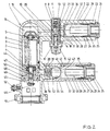
- a rotor 3 is rotatably mounted in one tubular part 2 by means of bearings 4 and 5 and is provided in the usual manner with radially movable fins 6, which alternately radially after the supply of compressed air are pressed outside to seal the space between the rotor 3 and the inner wall of the housing section 2 and thus to divide this interior space into two spaces, one of which is connected to a compressed air supply line and the other to an exhaust air line. Due to the pressure difference between the compressed air supply and exhaust air line, the rotor 3 rotates.
- the second part of the tubular housing 1 forms a compressed air supply line 7 and is provided with a valve 8 which has an external thread and is screwed into a bore 9 with an internal thread which is formed transversely to the pipe axis of the compressed air supply line 7.
- This threaded connection is designated by 10 in total.
- the valve 8 has a closing body 13 which can be pressed against a seat 12 by means of a spring 11 and is formed as a ball and which can be displaced against the action of the cedar 11 by means of a plunger 14 which has a push button 15 on the outside, as a result of which the flow to the engine interior 16 of the rotary piston air motor is released.
- the plunger 14 is guided in a housing bushing 17 of the valve 8, the gap 18 between the plunger 14 and the housing bushing 17 is so long and narrow that no ignition breakdown can occur.
- the valve 8 is arranged relatively close to the housing part 2 in which the rotor 3 is mounted.
- the engine interior 16 is connected via a bore 19 to a bore 20 of the valve 8, which leads to the valve seat 12.
- a bore 21 is provided in the valve 8, which is connected to a cylindrical cavity 22 in the compressed air supply line 7.
- a threaded plug 24 is screwed in by means of a threaded connection 23 and has a stepped inner bore.
- the outer, narrower inner bore 25 is used to connect a compressed air line, not shown, while the further inner bore 26 has an internal thread with which an external thread of an ignition breakdown barrier 28 interacts.
- This threaded connection is designated 27.
- the part of the threaded plug 24 which has the inner bore 26 forms a kind of inwardly projecting inner flange 29 with respect to the hollow cylindrical space 22 of the compressed air supply line 7, which carries the ignition breakdown barrier 28.
- This has an outer diameter which is smaller than the inner diameter of the hollow cylindrical space 22, so that through this gap 30 there remains sufficient flow cross section for the air flowing through the ignition breakdown barrier 28, which reaches the bore 21 of the valve 8 via short bores 31.
- the ignition breakdown barrier 28 is designed as a hollow cylinder and has a bottom 32 which is adjacent to the valve 8 and thus to the engine interior 16.
- the bottom 32 of the ignition breakdown barrier 28 to the bottom 33 of the cylindrical cavity 22 has a gap 34 which is sufficiently large for the flow of air.
- the opposite open end 35 of the ignition breakdown lock 28 is assigned to the threaded plug 24, which serves as a connection for the compressed air line, not shown, through which the rotary piston compressed air motor can be connected to a compressed air source.
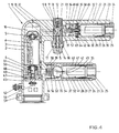
- an ignition breakdown block 28 is used, which is adjacent to the engine interior 16 with its bottom 32 and with its free open end 35 in the threaded plug 24 on its in the hollow cylindrical space 40 of the exhaust air line 37 as Inner flange 29 projecting part of the threaded plug 24 is screwed.
- the external thread of the ignition breakdown block 28 engages in the internal thread of the threaded plug 24 and thus forms the threaded connection 27 as in the case of the arrangement of the ignition breakdown block 28 in the compressed air supply line 7.
- a sufficiently large gap 41 is present between the ignition breakdown block 28 and the inner wall of the exhaust air line 37 , so that the exhaust air coming from the bore 36 can flow both through the base 32 and through the cylindrical wall of the ignition breakdown barrier 28 and into a line which can be screwed into the internal thread 25 of the threaded plug, but which is not shown in the drawing.
- a sufficiently large gap 43 is left between the bottom 32 of the ignition breakdown barrier 28 and the bottom 42 of the hollow cylindrical space 40 for the air flow.
- the rotor 3 is provided with a drive shaft which consists of two parts 44 and 45.
- the part 44 is connected directly to the rotor 3 and screwed into a blind hole in the part 45, which on the one hand serves as a stop for the bearing 4 and on the opposite end has a coupling 46 for driving a mixing device or a pump.
- the part 44 of the drive shaft 44, 45 is passed through a bore 47 in a housing bushing 48 designed as a threaded plug.
- This housing bushing 48 is by means of a threaded connection 49 in the housing part 2 screwed in.
- the gap remaining between the shaft part 45 and the bore 47 of the housing bushing 48 is denoted by 50.
- the housing part 2 With its free end, the housing part 2 extends beyond the coupling 46 and carries at its free open end an external thread 51 which serves to receive a union nut with which a device to be driven can be connected to this rotary piston compressed air motor. With 52 an earthing screw is designated, which serves for the discharge of static electricity.
- the gap 18 between the plunger 14 and the housing bushing 17 and the gap 50 between the part 45 of the drive shaft 44, 45 and the housing bushing 48 are dimensioned so narrow and so long that a sparking through is also prevented here.
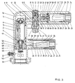
- FIGS. 2, 3 and 4 correspond to the embodiment according to FIG. 1 except for the following differences:
- a safety valve, generally designated 53, is provided within the exhaust air line 37 between the ignition breakdown barrier 28 and the bore 36, which comprises a ball 54, a valve seat 55 formed in the exhaust air line 37 and a spring 56 loading the ball 54.
- This configuration and arrangement is provided both in the embodiment according to FIG. 2 and in the embodiment according to FIG. 4.
- the ball 54 serving as the valve body projects into the hollow cylindrical space 40 receiving the ignition breakdown lock 28 and is lifted so far from its seat 55 when the ignition breakdown lock 28 is inserted that the air flowing through the rotary piston compressed air motor can escape. If the ignition breakdown barrier 28 in the exhaust air line is removed, the spring 56 presses the ball 54 against its seat 55, as a result of which the flow of air and thus the operation of the rotary piston compressed air motor is prevented.
- a safety valve is installed in the compressed air supply line 7 between the ignition breakdown barrier 28 and the valve 8, which comprises a valve plate 58, a valve tappet 59, a valve body 60 and a compression spring 61.
- the valve plate 58 is held in the compressed air supply line 7 by means of a locking ring 62 and is supported on a shoulder 63.
- the valve plate 58 is additionally sealed with a rubber seal 64 with respect to the compressed air supply line 7.
- the valve plate 58 is provided with a plurality of through bores 65 for the passage of the compressed air.
- valve tappet 59 In the center of the valve plate 58, the valve tappet 59 is guided, which is supported on the one hand with a plate-shaped extension 66 on the ignition breakdown barrier 28 and on the other end on the valve body 60.
- the firing arrestor 28 When the firing arrestor 28 is inserted, it presses the valve body 60 against the action of the spring 61 away from the valve plate 58 via the valve tappet 59, so that the compressed air supplied can flow through the bores 65 to the valve 8.
- the spring 61 presses the valve body 60 against the valve plate 58, whereby the bores 65 are covered. As a result, the compressed air supply is prevented.
Landscapes
- Engineering & Computer Science (AREA)
- Mechanical Engineering (AREA)
- General Engineering & Computer Science (AREA)
- Exhaust Gas After Treatment (AREA)
- Compressors, Vaccum Pumps And Other Relevant Systems (AREA)
- Compressor (AREA)
Priority Applications (1)
| Application Number | Priority Date | Filing Date | Title |
|---|---|---|---|
| AT88909729T ATE72296T1 (de) | 1987-11-25 | 1988-11-19 | Rotationskolben-druckluftmotor. |
Applications Claiming Priority (4)
| Application Number | Priority Date | Filing Date | Title |
|---|---|---|---|
| DE19873739982 DE3739982C1 (en) | 1987-11-25 | 1987-11-25 | Rotary-piston compressed-air engine |
| DE3739982 | 1987-11-25 | ||
| DE3828897A DE3828897C1 (enExample) | 1987-11-25 | 1988-08-25 | |
| DE3828897 | 1988-08-25 |
Publications (2)
| Publication Number | Publication Date |
|---|---|
| EP0401220A1 EP0401220A1 (de) | 1990-12-12 |
| EP0401220B1 true EP0401220B1 (de) | 1992-01-29 |
Family
ID=25862160
Family Applications (1)
| Application Number | Title | Priority Date | Filing Date |
|---|---|---|---|
| EP88909729A Expired - Lifetime EP0401220B1 (de) | 1987-11-25 | 1988-11-19 | Rotationskolben-druckluftmotor |
Country Status (4)
| Country | Link |
|---|---|
| EP (1) | EP0401220B1 (enExample) |
| AT (1) | ATE72296T1 (enExample) |
| DE (2) | DE3828897C1 (enExample) |
| WO (1) | WO1989004912A1 (enExample) |
Family Cites Families (6)
| Publication number | Priority date | Publication date | Assignee | Title |
|---|---|---|---|---|
| US3301194A (en) * | 1965-04-29 | 1967-01-31 | Dover Corp | Vane-type rotary pump |
| US3463384A (en) * | 1967-07-26 | 1969-08-26 | Allis Chalmers Mfg Co | Wear sensing means for rotary compressor |
| US3469500A (en) * | 1967-11-06 | 1969-09-30 | Ingersoll Rand Co | Vane-type fluid motor |
| JPS5121088B2 (enExample) * | 1972-02-19 | 1976-06-30 | ||
| DE3012715C2 (de) * | 1980-04-01 | 1987-02-26 | Gerhard 6980 Wertheim Lutz | Explosionsgeschützter Elektromotor |
| DE3613640A1 (de) * | 1986-04-23 | 1987-10-29 | Turmag Turbo Masch Ag | Druckluftmotor |
-
1988
- 1988-08-25 DE DE3828897A patent/DE3828897C1/de not_active Expired
- 1988-11-19 DE DE8888909729T patent/DE3868281D1/de not_active Expired - Lifetime
- 1988-11-19 EP EP88909729A patent/EP0401220B1/de not_active Expired - Lifetime
- 1988-11-19 WO PCT/DE1988/000725 patent/WO1989004912A1/de not_active Ceased
- 1988-11-19 AT AT88909729T patent/ATE72296T1/de not_active IP Right Cessation
Also Published As
| Publication number | Publication date |
|---|---|
| DE3828897C1 (enExample) | 1989-09-21 |
| ATE72296T1 (de) | 1992-02-15 |
| DE3868281D1 (de) | 1992-03-12 |
| EP0401220A1 (de) | 1990-12-12 |
| WO1989004912A1 (fr) | 1989-06-01 |
Similar Documents
| Publication | Publication Date | Title |
|---|---|---|
| DE4330819A1 (de) | Verbindung zwischen einer Dreh- oder Schwenkarmatur und einem Drehantrieb | |
| EP2881959B1 (de) | Betätigungsvorrichtung für ein explosionsgeschütztes Gehäuse | |
| EP2626567B1 (de) | Pumpengehäuse | |
| DE3604235A1 (de) | Spiralverdichter | |
| DE102013208536A1 (de) | Pumpenanordnung | |
| EP1193395A2 (de) | Innenzahnradpumpe | |
| DE2414589C3 (de) | Zündeinrichtung für eine Kreiskolben-Brennkraftmaschine | |
| EP0401220B1 (de) | Rotationskolben-druckluftmotor | |
| DE102016213797A1 (de) | Nockenwellenversteller | |
| DE19857560A1 (de) | Pumpe ohne eigene Lagerung | |
| DE3739982C1 (en) | Rotary-piston compressed-air engine | |
| DE2415814A1 (de) | Regelkondensator | |
| EP0594819B1 (de) | Rüttler mit eingebautem elektromotor | |
| EP0918932A1 (de) | Elektromotor-/pumpenaggregat | |
| DE19518290A1 (de) | Abstützelement für einen Schlepphebel eines Ventiltriebs einer Brennkraftmaschine | |
| DE3221111C2 (de) | Explosions- oder schlagwettergeschützte elektrische Kupplungssteckvorrichtung | |
| EP1413757A2 (de) | Motorpumpenaggregat | |
| DE2404317A1 (de) | Drucklufthandwerkzeug mit fluegelzellenmotor | |
| DE757940C (de) | Abdichtung beweglicher oder ortsfester Teile in den Durchtrittsoeffnungen keramischer Gehaeuse von explosionsgeschuetzten Geraeten | |
| DE102015211477A1 (de) | Hydrostatischer Kupplungsaktor | |
| DE19961567A1 (de) | Hydraulische Vorrichtung zur stufenlos variablen Nockenwellenverstellung | |
| EP1950770A2 (de) | Isolator | |
| EP1703616B1 (de) | Vorrichtung für den Schutz von Elektromotoren | |
| DE9416348U1 (de) | Wellenverbindung für einen Stromerzeuger | |
| EP0645789B1 (de) | Positionsschalter |
Legal Events
| Date | Code | Title | Description |
|---|---|---|---|
| PUAI | Public reference made under article 153(3) epc to a published international application that has entered the european phase |
Free format text: ORIGINAL CODE: 0009012 |
|
| 17P | Request for examination filed |
Effective date: 19900516 |
|
| AK | Designated contracting states |
Kind code of ref document: A1 Designated state(s): AT BE CH DE FR GB IT LI LU NL SE |
|
| 17Q | First examination report despatched |
Effective date: 19910225 |
|
| GRAA | (expected) grant |
Free format text: ORIGINAL CODE: 0009210 |
|
| AK | Designated contracting states |
Kind code of ref document: B1 Designated state(s): AT BE CH DE FR GB IT LI LU NL SE |
|
| PG25 | Lapsed in a contracting state [announced via postgrant information from national office to epo] |
Ref country code: IT Free format text: LAPSE BECAUSE OF FAILURE TO SUBMIT A TRANSLATION OF THE DESCRIPTION OR TO PAY THE FEE WITHIN THE PRE;WARNING: LAPSES OF ITALIAN PATENTS WITH EFFECTIVE DATE BEFORE 2007 MAY HAVE OCCURRED AT ANY TIME BEFORE 2007. THE CORRECT EFFECTIVE DATE MAY BE DIFFERENT FROM THE ONE RECORDED.SCRIBED TIME-LIMIT Effective date: 19920129 Ref country code: BE Effective date: 19920129 Ref country code: SE Effective date: 19920129 Ref country code: NL Effective date: 19920129 Ref country code: FR Effective date: 19920129 Ref country code: GB Effective date: 19920129 |
|
| REF | Corresponds to: |
Ref document number: 72296 Country of ref document: AT Date of ref document: 19920215 Kind code of ref document: T |
|
| REF | Corresponds to: |
Ref document number: 3868281 Country of ref document: DE Date of ref document: 19920312 |
|
| EN | Fr: translation not filed | ||
| NLV1 | Nl: lapsed or annulled due to failure to fulfill the requirements of art. 29p and 29m of the patents act | ||
| GBV | Gb: ep patent (uk) treated as always having been void in accordance with gb section 77(7)/1977 [no translation filed] | ||
| PG25 | Lapsed in a contracting state [announced via postgrant information from national office to epo] |
Ref country code: AT Effective date: 19921119 |
|
| PG25 | Lapsed in a contracting state [announced via postgrant information from national office to epo] |
Ref country code: LU Free format text: LAPSE BECAUSE OF NON-PAYMENT OF DUE FEES Effective date: 19921130 Ref country code: LI Effective date: 19921130 Ref country code: CH Effective date: 19921130 |
|
| PLBE | No opposition filed within time limit |
Free format text: ORIGINAL CODE: 0009261 |
|
| STAA | Information on the status of an ep patent application or granted ep patent |
Free format text: STATUS: NO OPPOSITION FILED WITHIN TIME LIMIT |
|
| 26N | No opposition filed | ||
| REG | Reference to a national code |
Ref country code: CH Ref legal event code: PL |
|
| PGFP | Annual fee paid to national office [announced via postgrant information from national office to epo] |
Ref country code: DE Payment date: 19941122 Year of fee payment: 7 |
|
| PG25 | Lapsed in a contracting state [announced via postgrant information from national office to epo] |
Ref country code: DE Effective date: 19960801 |