EP0400879A2 - Système à partage dynamique pour des réseaux privés - Google Patents
Système à partage dynamique pour des réseaux privés Download PDFInfo
- Publication number
- EP0400879A2 EP0400879A2 EP90305585A EP90305585A EP0400879A2 EP 0400879 A2 EP0400879 A2 EP 0400879A2 EP 90305585 A EP90305585 A EP 90305585A EP 90305585 A EP90305585 A EP 90305585A EP 0400879 A2 EP0400879 A2 EP 0400879A2
- Authority
- EP
- European Patent Office
- Prior art keywords
- channels
- network
- serving
- customer
- access links
- Prior art date
- Legal status (The legal status is an assumption and is not a legal conclusion. Google has not performed a legal analysis and makes no representation as to the accuracy of the status listed.)
- Granted
Links
Images


Classifications
-
- H—ELECTRICITY
- H04—ELECTRIC COMMUNICATION TECHNIQUE
- H04Q—SELECTING
- H04Q3/00—Selecting arrangements
- H04Q3/64—Distributing or queueing
- H04Q3/66—Traffic distributors
Definitions
- This invention relates to arrangements for providing telecommunication service to private customer networks.
- Virtual networks such as AT&T's Software Defined Network (SDN), set up call connections one at a time, in response to a dialed request from a caller, over the public switched network, while providing customer features, such as special in-network dialing arrangements.
- SDN Software Defined Network
- Such networks whose callers compete for service with the general public, do not provide the very high availability of dedicated private networks needed, for example, for inter-computer data transfers, necessary for the orderly conduct of a business.
- a digital facility consists of an access link between the customer premises and an AT&T serving office and an interoffice link provisioned from digital carrier systems connecting AT&T offices. Multiplexers in the major customer locations are used to derive both voice and data circuits fiom the digital facility.
- FIG. 1 Facilities are provisioned by a common carrier through static cross-connect arrangements such as the Digital Access and Cross Connect System manufactured by AT&T Technologies, in the serving office. For high bandwidth facilities such as those offered by Accunet T1.5 Service these cross-connections are manually patched between the carrier terminal equipment of digital carrier systems.
- a telecommunications network comprising a plurality of switching systems and interswitch transmission facilities comprises a pool of interswitch communication channels dedicated for use by a plurality of private networks.
- Each private network is connected to ones of a plurality of toll switches by access facilities.
- These access facilities define and limit the use of interswitch channels; the private customers are allowed to set up on demand any set of interconnections among their access facilities, the interconnections being provided by the pool of channels of the network.
- any interswitch channel(s) that is currently available may be assigned for connecting the access facilities specified in the message.
- a data base maintains a record of use of access facilities by the private customer to ensure that the private customer does not exceed his allotted capacity.
- Each switch maintains a record of the trunk groups and the busyidle status of all the channels (trunks) of the pool that are connected to that switch and maintains a routing data base for selecting an optimum route for connecting the access facilities to be connected in response to any request.
- the pool is engineered to provide sufficient transmission facilities to interconnect all the access facilities of the private network customers in any combination, and to provide an adequate number of extra facilities to be used in case of failure of one or more of the facilities in the pool. This permits each of the customer admimstrators to draw facilities from the pool without exhausting the pool and without requiring permission from a network administrator.
- a shared public network also used for public telecommunications service is used to provide facilities for such a dynamically shared facility network (DSFN).
- communications channels of the large communications facilities of the public switched network can be allocated to the DSFN, thus achieving economies of scale.
- the large and flexible toll switching systems of the public switched network can be conilgured to control and switch the channels of the DSFN.
- such sharing eliminates the need for tandem points in customer premises equipment of the private networks.
- the network can be used to switch communication channels at switching points in the network to allow the customer to redirect or reallocate subscribed capacity among the customer's various private network locations so that that capacity may be used most advantageously. This is accomplished by selecting different channels from the dedicated pool to be used for handling that customer's most immediate traffic needs.
- the DSFN is engineered so that the prespecified peak demands of all the private customer networks can be met simultaneously at any point in time.
- This engineering is based on limiting the access of each access point of each private customer network and limiting the set of such access points which may communicate for each private customer network.
- This arrangement differs from the current public switched network in that demand is unconstrained and the network is provisioned to carry a forecasted peak demand and is partially idle during off peak hours.
- the engineered pool is augmented by physically diverse facilities and adequate additional capacity sufficient to allow for the restoral of normal service in the event of failure of part of the regular facilities.
- the failure When a failure occurs in the facility carrying channels which have been assigned to a particular private network, the failure may be detected in the customer's equipment; a request message is then automatically sent to the DSFN to reassign traffic on those channels to other available facilities.
- the control of the public network can be used to control this function also.
- the fraction of additional communications channels which must be provided to assure the required level of reliability is lower in a DSFN than in a group of disjoint private networks.
- the communications channels are automatically made available in the pool of facilities for use by other private networks by making these channels available in the data tables of the switches. This is made possible because the pool of facilities of a DSFN are subject to an overall flexible repair and administration scheme which makes a restored facility immediately available for carrying new traffic.
- the invention provides for the administration of private networks as part of the overall process of administering the shared public network.
- Such administration takes advantage of the economies of scale offered by the large administrative systems that are present in shared public networks. Indeed, this reduces administration costs for such private networks.
- the public switched network illustratively provides a CCITT standard Integrated Services Digital Network (ISDN) interface for communicating with customer access equipment.
- ISDN Integrated Services Digital Network
- Such an arrangement permits a wide range of customer equipment to interface in a standard way with the DSEN. It also provides out-of-band signaling to provide the command and control signaling allowing the communications channels to be combined into variable transmission rate groups and allowing reestablishment of failed channels.
- the invention enables two or more private networks to share units of capacity such as a 24 channel T digital carrier facility and resultingly to increase utilization of interoffice facilities.
- a feature of the invention is that a customer administrator of a private network initiates a change of facilities to respond to changes in the traffic pattern of a private network by means of the aforementioned signals from the private network. Accordingly, the private network is immediately reconfigured to meet this request, without requiring intermediate processing of service orders by the public network administrator.
- failures of facilities transporting customer channels are signaled via the aforementioned standard out-of-band signaling channel to customer access equipment.
- customer access equipment signals for a reconnection which is routed by the network switch over a diverse network facility with redundant capacity.
- each private network customer has access to the public switched network via dedicated access facilities. Connections within the customer's private network provided according to this invention are established only between these dedicated access facilities. These dedicated access facilities therefore define the scope of the private network assigned to that customer. These constraints define the required traffic capacity of the shared pool of facilities and permit the shared pool to be properly provisioned. As a result, customer administrators are free to request facilities for any traffic pattern meeting these constraints, i.e., the dedicated access facilities, without causing an overload of the shared pool; effectively, if a private network administrator legitimately requests more capacity for one route, capacity of other routes is diminished.
- a customer service controller is used for interfacing between the customer equipment and the network.
- the controller detects failures in the communication channels of a path and automatically sends a message to the network to request the establishment of an alternate path.
- the controller also maintains a record of the status of the customer's network configuration.
- the controller signals to the network over a Primary Rate Interface (PRI) of an Integrated Services Digital Network (ISDN) connection to the network.
- PRI Primary Rate Interface
- ISDN Integrated Services Digital Network
- a pool of transmission channels interconnecting a plurality of switching systems is dedicated for use by a plurality of private networks which request connections between their access facilities to the switching systems by sending a request message to one of the switching systems which responds to this message by causing the requested connection to be established using channels selected from the dedicated pool.
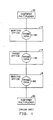
- FIG. 1 is an illustration of the prior art.
- Customer multiplexers 90 located on customer premises are connected via carrier systems to serving offices 10 and 8.
- These serving offices comprise cross-connects 102 and 82 respectively, for connecting individual trunks from one carrier system to another carrier system that interconnects the serving offices to an intermediate tandem office 14.
- the tandem office also comprises a cross connect 142 for interconnecting trunks terminating on the tandem office.
- serving offices may be interconnected through a plurality of tandem offices, through other serving offices or directly, in all cases via a cross-connect facility.
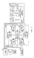
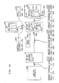
- FIG. 2 is an overall block diagram illustrating one embodiment of the invention.
- a transmission network 220 comprising 7 serving offices, 2,4,6,8,10,12 and 14 is used for interconnecting the private service customers.
- the 7 serving offices are toll switches such as the 4 ESSTM switches described in The Bell System Technical Journal, Vol. 56, No. 7, September 1977, pages 1015-1320, and comprise switching networks for setting up temporary or long term connections and facilities switching arrangements for taking incoming groups of channels and routing them to outgoing groups of channels.
- the 6 serving offices on the periphery, offices 2,4,6,8,10, and 12 are each connected to one other peripheral serving office and are each connected to the central serving office 14.
- Each of the 7 serving offices, 2,4,6,8,10,12 and 14 is also connected to a common channel signaling network 230 which is used to pass signaling information among these switches and which is used for accessing a data base called a Network Control Point (NCP) 240.
- NCP Network Control Point
- Each of the serving offices also has additional channels 1 for connecting to other serving offices; these other channels together with the connections shown form the pool of channels dedicated for providing service to a plurality of private service customers.
- the Network Control Point 240 is used for translating signaling information into network physical addressing for routing and is used in conjunction with restricted access to the pool of channels to ensure that individual private networks do not exceed their assigned capacity.
- Connected to the NCP 240 is a service administrator's terminal 242 used for administration of the customer specific data relating to network 220 in the NCP 240, and for assigning channels to the dedicated pool.
- the shared facilities are derived from carrier systems common to the public telephone network but carry only connections originated from private network users who subscribe to the DSFN.
- Public telephone traffic is carried on separate trunking facilities. This assignment along with the demand restricted by the access facilities assures a level of availability comparable to that of dedicated facilities which is unaffected by unusual public telephone network demand.
- advanced routing algorithms can be used which allow the facilities to be further shared with public telephone traffic. Such algorithms logically reserve channels on the shared trunking for each service and allow priority, for example, to DSFN when overload conditions develop. Such routing schemes create further economies of scale in sharing but may have different performance characteristics.
- Block 250 illustrates a typical private network user connection to network 220.
- the interface between the shared transmission network 220 and the private customer is a service controller 255 connected to a serving office 12 by a facility operating under the protocol of an Integrated Services Digital Network (ISDN) Primary Rate Interface (PRI) 257.
- ISDN Integrated Services Digital Network
- PRI Primary Rate Interface
- This PRI comprises 23 B-channels, each 64-Kilobit per second (Kb/s), for carrying voice or data communications, and one 64 Kb/s D-channel for carrying signaling information.
- the service controller 255 is connected to an administrative terminal 260 for administering the private network by, for example, entering the network addresses of endpoints to be connected or receiving status information concerning endpoints.
- a connection is shown from the service controller to a computer 264.
- a user terminal such as terminal 274, but at another customer location connected to' another serving office, is connected via the network 220 to computer 264.
- the voice and switched data traffic of the private network is transmitted via connection 276 between the service controller 55 and private branch exchange (PBX) 270.
- PBX private branch exchange
- a second connection via link 278 connects the service controller to the private branch exchange for serving public switched network traffic from PBX 270. This connection may share the access facility to the serving office 4 for the purpose of placing calls on the public network.
- the PBX is connected to user station 272 and user terminal 274.
- Service controller 255 is a Unit, such as the Acculink® Model 740 of AT&T Information Systems, which can readily be adapted to perform the following functions:
- the PRI is described, for example, in "AT&T Integrated Services Digital Network (ISDN) Primary Rate-Interface Specification", AT&T Document TR 41449, March 1986, and in the CCITT Red Book Vol. 3, Fascicle 3.5, Series 1, ISDN Recommendations, Geneva, 1985.
- ISDN Integrated Services Digital Network
- FIGS. 3-17 illustrate how a network such as the one described with respect to FIG. 2, can be used to provide private service economically.
- the problems include the following:
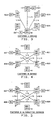
- FIG. 3 illustrates the traffic demand of customer A.
- the units are in fractions of a T-carrier facility so that one quarter corresponds to six channels of 64 kilobits per second each or 384 kilobits per second.
- Customer A's network consists of terminations on serving offices 10,12,2,4 and 6. All of the demand by customer A is for connections between customer A's equipment connected to switch 6 and the equipment connected to serving offices 10,12,2 and 4. There is no demand for traffic among the stations terminated at serving offices 10,12,2 and 4. The traffic demand is for one quarter unit from each of the serving offices 10,12,2, and 4 to switch 6.
- FIG. 4 illustrates the demand of customer B.
- Customer B is connected to serving offices 2,4,8, and 10 and the typical demand is for a quarter unit of traffic between 2 and 10,2 and 4,2 and 8,4 and 8, and 4 and 10.
- the maximum demand generated at the connections to serving offices 2 and 4 is three quarters of a unit each and the maximum demand generated at the connections to serving offices 8 and 10 is one half unit each.
- FIG. 5 illustrates alternative demands of customer B.
- the alternative demands are that serving offices 2 and 4 can generate or terminate up to three quarters of a unit of demand each and serving offices 10 and 8 can generate up to half a unit of demand each and that any interconnection within this restraint is allowed.
- the actual physical network is shown within block 20 of FIG. 2. It comprises a star wherein serving offices 2,4,6,8,10 and 12 are connected to central serving office 14 and in addition, there are facilities between serving offices 12 and 2; 4 and 8; and 6 and 10. Thus, each of the peripheral serving offices 2,4,6,8,10 and 12 have two geographically and physically diverse output links and serving office 14 has six such links.
- FIG. 6 illustrates a dedicated private network for customer A having no redundancy.
- each serving office has a cross-connect facility for establishing the connections required for the private networks.
- Blocks 501,503,505,507 and 509 represent the interface equipment such as service controller 255 connected to a cross-connect facility in one of the serving offices.
- Blocks 509 and 507 are represented as being connected to serving offices 6 and 10 by a single line to indicate the fact that no tandem switching takes place at these interfaces.
- a double line is shown connecting blocks 501,503, and 505 to serving offices 12,2, and 4 to indicate that the interface of these three serving offices performs a tandeming function, that is, a function of switching incoming circuit demand directly to outgoing facilities as well as performing the function of connecting locally generated demand to the network.
- a tandeming function that is, a function of switching incoming circuit demand directly to outgoing facilities as well as performing the function of connecting locally generated demand to the network.
- interface 501 switches the demand from interface 509 directly to interface 503, in addition to adding its own demand to that headed for that interface.
- the tandeming function is performed at the switching network within serving offices in the shared networks of this description.
- each of the links 511,512,513,514,515,516, and 517 is adequate for carrying a full unit of traffic though the requirements indicated in parentheses for each of these links varies from one quarter (links 511 and 512) to one half (link 513) to three quarter (links 514 and 515) to one (links 516 and 517).
- Those links interconnecting two serving offices which are not directly connected in the transmission network 20, such as serving offices 10 and 12, are shown as two separate links 511 and 512 connected by a permanent connection 520 within serving office 14.
- links 514 and 515 interconnecting serving offices 2 and 4 are connected by a permanent connection 522 and links 516 and 517 interconnecting serving offices 4 and 6 are connected by a permanent connection 524 within serving office 14. Notice that in order to meet customer A's demand using a dedicated network, a total of seven links are required to provide nonredundant service.
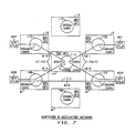
- FIG. 7 illustrates a dedicated network which can meet the demands of customer B.
- Interface equipment 601,603,605, and 607 each comprising a service controller 255 on serving offices 2,4,8, and 10 are used by customer B for interfacing with the dedicated network.
- Links 611 and 612 which are connected by connection 620 in serving office 14 interconnect customer B terminations on serving offices 2 and 4.
- Interface 603 provides a tandeming function to switch demand from the interface 601 to interfaces 605 and 607, as well as to interface 603.
- Link 613 interconnects serving offices 4 and 8 directly and links 614 and 615 connected via a connection 622 within switch 14 interconnect interfaces 605 and 607.
- Interface 605 also provides a tandeming function to switch demand from interface 607 to interfaces 603 or 601 as well as to termination 605.
- the total number of links required to serve customer B using a dedicated network without redundancy is five.
- FIG. 8 is a superposition of FIGS. 6 and 7 and indicates that to meet the total demand for the private networks of customers A and B using dedicated facilities requires 12 links: one unit of traffic over route 701 between serving offices 12 and 2; two units of traffic over the route 703 between serving offices 2 and 14; three units of traffic over route 705 connecting serving offices 14 and 4; one unit of traffic over route 707 connecting serving offices 4 and 8; one unit of traffic over route 709 connecting serving offices 8 and 14; two units of traffic over route 711 connecting serving offices 10 and 14; one unit of traffic over route 713 connecting serving offices 12 and 14; and one unit of traffic over route 715 connecting serving offices 6 and 14.
- FIGS. 9-11 switching is performed at each serving office and partial units of traffic can be merged onto a full unit of traffic using this switching capability.
- the interfaces at the customer premises comprise units 255, and the interfaces are shown as blocks 502,504,506,508 and 510 for customer A, and as blocks 602,604,606 and 608 for customer B.
- customer A's demands can be met using routes 801,803,805, and 807 joining serving offices 12,2,4 and 10, respectively, to serving office 14 and each carrying one quarter of a unit of traffic to route 809 connecting serving office 14 to serving office 6 and carrying a full unit of traffic. This requires only five links in contrast to the seven links required in FIG. 6.
- FIG. 10 illustrates how customer B's demands can be met through four links over routes 901,903,905, and 907 carrying three quarters, three quarters, one half and one half a unit of traffic apiece. This contrasts with five links required in the configuration of FIG. 7 to carry the same traffic.
- FIG. 11 illustrates that six links can carry all the traffic required by customers A and B.
- a single route 1001 is all that is required to carry traffic from serving office 14 to serving office 12 for termination on unit 502; a single route carrying one unit of traffic is all that is required for connecting serving office 14 to serving office 2 for switching of that traffic to interfaces 504 and 602; a single unit of traffic is all that is required over link 1005 connecting serving office 12 and serving office 14 for switching traffic to interfaces 506 and 604; a single link carrying one unit of traffic is all that is required for route 1007 between serving offices 14 and 6; interface 508; a single link is all that is required on route 1009 connecting serving office 14 with serving office 8 to carry one half unit of traffic to interface 606 and a single link is all that is required on route 1011 to carry three quarters of a unit of traffic switched between serving office 10 and serving office 14 for interfaces 510 and 608. This is half the number of links shown in FIG. 8 to meet the demand
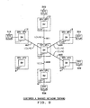
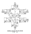
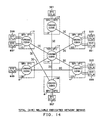
- FIGS. 12-14 illustrate the configuration required to achieve a reliable dedicated network.
- a reliable network is defined for the purposes of these figures as a network which will survive the loss of any one link.
- FIG. 12 shows that a reliable network for serving customer A can be implemented using nine links.
- the links interconnecting switches 12,2; 2,14, and 14,4; 6,14, and 14,8, and 8, 4; 6,10; and 10,14 and 14,12.
- the same set of links differently configured as shown in FIG. 13 can provide customer B with a reliable dedicated network.
- the links include one connecting switches 2,12 and 12,14 and 14,10; 2,14 and 14,4; 4,8; 8,14 and 14,6 and 6,10. Notice that in both of these cases, several double and triple route links are required to join two serving offices. This is a consequence of the desire to avoid using the same route for redundant links.
- FIG. 14 is then simply a superposition of the links of FIGS. 12 and 13 and requires a total of eighteen links.
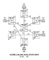
- FIGS. 15-17 demonstrate that this number can be halved by using a shared network approach.
- FIG. 15 illustrates that the links needed for reliable interconnection of terminations 502,504,506,508, and 510 of customer A's network is nine links, the same nine links as indicated in FIG. 12.
- FIG. 16 nine links are required to provide customer B with a reliable shared network.
- FIG. 17 halving the total number of links required for a reliable network using unshared facilities without switching.
- FIGS. 6 and 9 illustrate the advantage of a shared network in eliminating backhaul, i.e., the process of going through a number of serving offices in order to connect adjacent serving offices.
- FIGS. 9-11 illustrate the sharing of channels on a facility to reduce the total number of links required.
- FIGS. 7 and 10 illustrate the advantages of use of switching to respond to shifts in demand.
- FIGS. 12 through 17 illustrate how redundancy can be obtained at lower cost in a shared switchable network.
- FIG. 14 illustrates that eighteen links are required to achieve a reliable dedicated network, whereas, FIG. 17 shows that only nine links are required if the network can be shared.
- FIG. 17 shows a redundant and geographically diverse network wherein traffic over a facility containing any cable break can be routed over another facility.
- FIG. 18 illustrates the procedures and network data necessary for the service controller to establish a connection, and the means by which the network switching elements are able to control demand and route requested connections.
- the customer network administrator at terminal 260 (FIG. 2) is assigned by the carrier network administrator access channel numbers and dialable addresses (directory numbers) for each of the endpoints subscribed to the network. These data are entered into the service controllers by the customer admimstrator and into the network switch and Network Control Point by the network administrator. Further the network administrator assigns a network address for each endpoint as well as a set of address translations which convert dialable addresses to network addresses. The latter translations which are customer specific are placed in the Network Control Point and associated with each network address. Translations are provided only for allowed calls.
- Each of the serving offices comprises a switching network for establishing connections.
- Service controller 255 shown in detail in FIG. 20, comprises an interface 2003 for interfacing with the access channels to serving office 4.
- The5interface is a PRI interface with one signaling channel 2005 for communicating with a customer administrative terminal 260 and a processor 2000 for controlling the service controller.
- the processor 2000 comprises a central processing unit 2002, a memory 2009 including table 2010 for storing access patterns of the service controller, table 2006 for storing channel usage data, and a program 2007.
- the processor 2000 communicates with serving office 4 via the signaling channel 2005.
- the output of the interface is also connected via channels 2004 to the customer equipment 264,270.
- a call is illustrated between dialable addresses W on serving office 4, and X on serving office 8; both W and X are dialable addresses of customer B.
- Dialable addresses are upper case letters W, X, Y, Z; network (physical) addresses are lower case letters w, x, y, z.
- the service controller 255 upon command from the customer administrator's terminal 260, checks in Table 2010 to see how many channels can be accessed for the various allowable outgoing addresses, X, Y, and Z. Segment 2014 indicates that 12 channels are allowed for X, 12 for Y, and 18 for Z. Segment 2010 indicates that the total number of channels allowed at any one time is 18, identifies these as 1-18, and identifies the directory number, W, of the source.
- Service controller 255 lnitiates a call to X by sending a setup message 2020 over the primary rate interface (PRI) containing the following information elements: dialable addresses X and W (2021), number of channels (6) (2023), assigned channels (7-12) (2025) and the type of service (DSFN) (2027) for which the connection will be established.
- the serving office 4 interprets the service type and network address in order to check a table 2010 of allowed access channels.
- the serving office 4 formulates a Common Channel Signaling (CCS) message (2040) containing the network address w of the originating access line and dialable address X, (segment 2042), service type (segment 2044), and a call ID (segment 2046).
- CCS Common Channel Signaling
- This message is transmitted to the Network Control Point (NCP) 240.
- NCP Network Control Point
- the network address along with the service type determines the message routing to the correct NCP and customer data record in the NCP. If the number or type of access channels is not correct, or is inadequate, the call is blocked by the switch by signaling a call denial message to the source controller.
- the Network Control Point 240 uses the received information to verify that the customer has subscribed to the desired service, and to access a table 2050 containing the network address translations, i.e., translations from the dialable address to the network address, for allowed network addresses for calls originating from network address w.
- the network address is a concatenation of the terminating switch address and the terminating address of the access line at that switch. If the desired dialable address, X, is an allowed translation for w, then a return message 2060 containing the call ID 2064 and the routing translation (2062) comprising the network addresses w, x, of the two endpoints is sent to the originating serving office. If not, a call denial message is sent to the serving office which in turn blocks the call. The details of the call denial are returned to the customer administrator and provide useful trouble shooting information.
- the data at the serving office associated with the call ID and the translated routing number are used to proceed with the routing of the call.
- Service type, network address and bandwidth data are used to point to a routing table 2070 within the serving office 4 which contains a list in preferred order of the outgoing facilities which can transport the call to its destination. Only the terminating switch address portion of the network address is needed to determine routing.
- These facilities are dedicated to the service and engineered to give a very low level of blocking given the known demand and statistical failure rate of facilities.
- the set of outgoing facilities traverse at least two physically diverse paths. The preferred routes are searched in order until an idle set of channels is found.
- trunk group m (2082), a direct route to destination serving office 8
- trunk group n (2084), a route that goes via tandem serving office 14.
- trunk group m is available.
- a table (not shown) of trunks of trunk group m is searched to find an available set of channels for the connection.
- Subsequent serving offices in the network based on incoming trunk type and Common Channel Signaling data in the form of call type and terminating network address will further route the call to the desired terminating switch. At any point where the call cannot be further routed due to lack of facilities, the call will be terminated. Routing schemes such as Dynamic Non-Hierarchical Routing which allows the call to be automatically reattempted at the originating switch until all possibilities are exhausted can also be employed.
- serving office 4 sends a CCS message 2090, comprising segments 2091 (x, network address of the destination, W, dialable address of the source), 2093(6, the number of channels for this call), 2095(13-18, the channels of the trunk group, assumed in this case to be a single 24 channel group, that have been assigned to this call) 2097 (m, the identity of the trunk group) and 2099 (DSFN, the type of service for this call).
- message 2090 is received in serving office 8
- the access privilege for network address x are checked in table 2100, and it is found that the service controller 256 has been assigned to channels 1-12 on the access facility.
- Serving office 8 sends a message 2110 to service controller 256 to establish the requested connections.
- Message 2110 comprises segments 2111 (dialable addresses X, W of source and destination), 2113(6, the number of channels of the connection), 2115 (1-6, the channels assigned to the connection) and 2117 (DSPN, the type of service).
- Upon positive acknowledgment the call is completed and a connect message is transmitted to the originating service office 4 and service controller 255. If the appropriate channels are inadequate in number or non-existent the call is blocked.
- messages relating the status of the call are sent to service controller 255. If the call is blocked, an abnormal event, a code in the denial message to service controller 255 will indicate the cause of blocking. This information would be displayed at the customer administrator's terminal 260 by the service controller 255.
- a connection is held indefinitely. Severe noise or failure of the network facilities can cause the serving offices 4 or 8 or the service controller 255 or 256 to disconnect. Under these condition, the service controller 255 or 256 would automatically reestablish the connection as described above.
- a serving office will take very noisy or failed trunks out of service, for example, trunk groupm.
- trunk group n When the call is reestablished, since the old route is unavailable, a new route will be selected by the serving office, in this case, trunk group n.
- the engineering of the network facilities assures that there will be a physically diverse facility with adequate capacity to carry the redirected connection.
- FIG. 19 is a flow diagram of the functions performed as described in FIG. 18.
- a serving office receives a request to establish a DSFN connection (action block 2200).
- a connection is then set up between the originating serving office and the service controller from which the request was received (action block 2210).
- An NCP (in this case NCP 240) is then accessed to derive the physical address of the destination from the directory number of that destination (action block 2220).
- the originating serving process selects a route based on the identity of the destination serving office (action block 2230).
- a connection is set up between the originating serving office and the destination serving office and between the destination serving office and the serving office controller at that destination (action block 2240).
- the customer administrator may disconnect existing connections and establish new connections of different bandwidths to the set of predefined locations identified in the Network Control Point.
- the only constraint is that the total bandwidth between two endpoints cannot exceed the bandwidth of the access channels assigned to the service. If the customer administrator desires additional bandwidth or new locations, a service order to the network administrator is necessary. If adequate network capacity exists without adding new facilities, the network administrator may grant service by updating the appropriate tables in the switch and Network Control Point. This ability to do this allows the potential of granting service in a significantly shorter interval than that required to provision a customer dedicated facility which must be manually routed.
- Network Control Point database processing system
- translations which vary by time of day and date
- subscriber activated translations changes
- centralized monitoring of connection patterns These features could be implemented at the service controller but would be more difficult to administer and control in those devices.
Landscapes
- Engineering & Computer Science (AREA)
- Computer Networks & Wireless Communication (AREA)
- Data Exchanges In Wide-Area Networks (AREA)
- Telephonic Communication Services (AREA)
- Sub-Exchange Stations And Push- Button Telephones (AREA)
- Monitoring And Testing Of Exchanges (AREA)
Applications Claiming Priority (2)
| Application Number | Priority Date | Filing Date | Title |
|---|---|---|---|
| US07/359,015 US4993014A (en) | 1989-05-30 | 1989-05-30 | Dynamic shared facility system for private networks |
| US359015 | 1989-05-30 |
Publications (3)
| Publication Number | Publication Date |
|---|---|
| EP0400879A2 true EP0400879A2 (fr) | 1990-12-05 |
| EP0400879A3 EP0400879A3 (fr) | 1992-12-16 |
| EP0400879B1 EP0400879B1 (fr) | 1996-08-21 |
Family
ID=23411973
Family Applications (1)
| Application Number | Title | Priority Date | Filing Date |
|---|---|---|---|
| EP90305585A Expired - Lifetime EP0400879B1 (fr) | 1989-05-30 | 1990-05-23 | Système à partage dynamique pour des réseaux privés |
Country Status (5)
| Country | Link |
|---|---|
| US (1) | US4993014A (fr) |
| EP (1) | EP0400879B1 (fr) |
| JP (2) | JP2705839B2 (fr) |
| CA (1) | CA2014408C (fr) |
| DE (1) | DE69028142T2 (fr) |
Cited By (6)
| Publication number | Priority date | Publication date | Assignee | Title |
|---|---|---|---|---|
| ES2048081A2 (es) * | 1991-11-08 | 1994-03-01 | Telefonica Nacional Espana Co | Sistema de encaminamiento automatico para red digital integrada. |
| EP0616479A1 (fr) * | 1993-03-19 | 1994-09-21 | Thomson-Csf | Procédé de reconfiguration d'un réseau maillé |
| WO1998008346A1 (fr) * | 1996-08-16 | 1998-02-26 | British Telecommunications Public Limited Company | Etablissement d'un circuit prive dans un reseau de telecommunications |
| EP0828396A1 (fr) * | 1996-08-16 | 1998-03-11 | BRITISH TELECOMMUNICATIONS public limited company | Approvisionnement de circuits privés dans un réseau de télécommuncations |
| EP0932313A1 (fr) * | 1998-01-27 | 1999-07-28 | Siemens Aktiengesellschaft | Dispositif de contrÔle de congestion pour un commutateur téléphonique |
| US6535597B2 (en) | 1996-08-16 | 2003-03-18 | British Telecommunications Public Limited Company | Private circuit provision in a telecommunications network |
Families Citing this family (49)
| Publication number | Priority date | Publication date | Assignee | Title |
|---|---|---|---|---|
| CA2015248C (fr) * | 1989-06-30 | 1996-12-17 | Gerald R. Ash | Reseau de communication a partage total |
| JP2880268B2 (ja) * | 1990-07-30 | 1999-04-05 | 株式会社日立製作所 | ネットワーク構成定義情報の変更方法 |
| JPH04154242A (ja) * | 1990-10-17 | 1992-05-27 | Nec Corp | ネットワーク障害回復方式 |
| WO1992021185A1 (fr) * | 1991-05-24 | 1992-11-26 | Bell Atlantic Network Services, Inc. | Systeme d'interface de reseau numerique a integration de services (rnis) d'ordinateurs personnels |
| US5444703A (en) * | 1991-05-24 | 1995-08-22 | Gagliardi; Ugo O. | ISDN interfacing of personal computers |
| US6295615B1 (en) | 1991-12-09 | 2001-09-25 | Sprint Communications Company, L. P. | Automatic restoration of communication channels |
| US5577196A (en) * | 1993-04-07 | 1996-11-19 | Sprint Communications Co. L.P. | Intelligent digital signal hitless protection switch |
| US5506956A (en) * | 1993-04-07 | 1996-04-09 | Sprint Communications Company L.P. | Error correction and channel restoration apparatus for T1 digital links |
| US5577042A (en) * | 1994-01-18 | 1996-11-19 | Mcgraw Broadcast | Broadcast and presentation system and method |
| US6430195B1 (en) | 1994-05-05 | 2002-08-06 | Sprint Communications Company L.P. | Broadband telecommunications system interface |
| WO1995031057A1 (fr) | 1994-05-05 | 1995-11-16 | Sprint Communications Company, L.P. | Procede, systeme et appareil de commande d'un systeme de telecommunications |
| US6633561B2 (en) | 1994-05-05 | 2003-10-14 | Sprint Communications Company, L.P. | Method, system and apparatus for telecommunications control |
| US6314103B1 (en) | 1994-05-05 | 2001-11-06 | Sprint Communications Company, L.P. | System and method for allocating bandwidth for a call |
| US6031840A (en) * | 1995-12-07 | 2000-02-29 | Sprint Communications Co. L.P. | Telecommunications system |
| US6172977B1 (en) * | 1994-05-05 | 2001-01-09 | Sprint Communications Company, L. P. | ATM direct access line system |
| US5878277A (en) * | 1995-05-23 | 1999-03-02 | Hitachi Denshi Kabushiki Kaisha | Communication system having at least two types of communication channels |
| US5912882A (en) | 1996-02-01 | 1999-06-15 | Qualcomm Incorporated | Method and apparatus for providing a private communication system in a public switched telephone network |
| US5870550A (en) * | 1996-02-26 | 1999-02-09 | Network Engineering Software | Web server employing multi-homed, moldular framework |
| US5875234A (en) | 1996-02-14 | 1999-02-23 | Netphone, Inc. | Computer integrated PBX system |
| US8117298B1 (en) | 1996-02-26 | 2012-02-14 | Graphon Corporation | Multi-homed web server |
| US5940393A (en) * | 1996-05-28 | 1999-08-17 | Sprint Communications Co. L.P. | Telecommunications system with a connection processing system |
| US6130935A (en) * | 1996-08-08 | 2000-10-10 | Mci Communications Corporation | Virtual networking work at home system and method |
| US5828652A (en) * | 1996-09-30 | 1998-10-27 | Lucent Technologies, Inc. | Establishment of a flexible rate interface link to restore channels from a failed communication link |
| US5991263A (en) * | 1996-09-30 | 1999-11-23 | Lucent Technologies Inc. | Channel and data link automatic restoration |
| US6014378A (en) * | 1996-11-22 | 2000-01-11 | Sprint Communications Company, L.P. | Telecommunications tandem system for circuit-based traffic |
| BR9713283A (pt) | 1996-11-22 | 1999-10-26 | Sprint Communications Co | Sistema e método para o transporte de uma chamada em uma rede de telecomunicações |
| BR9809557A (pt) * | 1997-01-24 | 2000-10-17 | Extricity Software Inc | "método para coordenar um processo entre um primeiro local e um segundo local e método para criar uma definição de processo". |
| US6067299A (en) * | 1997-04-16 | 2000-05-23 | Sprint Communications Company, L.P. | Communications system for providing ATM connections and echo cancellation |
| US6704327B1 (en) | 1997-05-09 | 2004-03-09 | Sprint Communications Company, L.P. | System and method for connecting a call |
| US6178170B1 (en) | 1997-05-13 | 2001-01-23 | Sprint Communications Company, L. P. | System and method for transporting a call |
| US6021136A (en) * | 1997-07-30 | 2000-02-01 | At&T Corp. | Telecommunication network that reduces tandeming of compressed voice packets |
| US6912222B1 (en) * | 1997-09-03 | 2005-06-28 | Internap Network Services Corporation | Private network access point router for interconnecting among internet route providers |
| US5999797A (en) * | 1997-11-03 | 1999-12-07 | Motorola, Inc. | Method and apparatus for providing private global networks in a satellite communication system |
| US5956343A (en) * | 1997-12-23 | 1999-09-21 | Alcatel Usa Sourcing L.P. | Designating a control channel in a telecommunications system |
| US6160871A (en) | 1998-04-10 | 2000-12-12 | Sprint Communications Company, L.P. | Communications test system |
| AU6916300A (en) * | 1999-08-19 | 2001-03-13 | Armillaire Technologies, Inc. | Communication resource fault detection |
| US6816497B1 (en) | 1999-11-05 | 2004-11-09 | Sprint Communications Company, L.P. | System and method for processing a call |
| JP3961763B2 (ja) * | 2000-11-22 | 2007-08-22 | 株式会社エヌ・ティ・ティ・ドコモ | 複数ネットワーク接続型通信システムの基地局およびその接続方法 |
| US6609945B2 (en) * | 2001-02-08 | 2003-08-26 | Plexus, Inc. | Radio-controlled toy blimp with infrared beam weapons for staging a gun battle |
| US7406165B2 (en) * | 2001-03-05 | 2008-07-29 | Sbc Properties, L.P. | Direct route ISDN primary route interface |
| US20040047346A1 (en) * | 2002-07-10 | 2004-03-11 | Vandendorpe James Edward | Large telecommunications network |
| KR100513022B1 (ko) * | 2002-09-10 | 2005-09-05 | 삼성전자주식회사 | 무선 고속 데이터 시스템에서 공중망과 사설망의 데이터위치 저장기 공통 사용 방법 및 시스템 |
| US8213299B2 (en) * | 2002-09-20 | 2012-07-03 | Genband Us Llc | Methods and systems for locating redundant telephony call processing hosts in geographically separate locations |
| US8139729B2 (en) * | 2005-04-27 | 2012-03-20 | Verizon Business Global Llc | Systems and methods for handling calls associated with an interactive voice response application |
| US20080285436A1 (en) * | 2007-05-15 | 2008-11-20 | Tekelec | Methods, systems, and computer program products for providing site redundancy in a geo-diverse communications network |
| US20090216893A1 (en) * | 2008-02-25 | 2009-08-27 | International Business Machines Corporation | Buffer discovery in a parrallel multi-tasking multi-processor environment |
| US8762125B2 (en) * | 2008-02-25 | 2014-06-24 | International Business Machines Corporation | Emulated multi-tasking multi-processor channels implementing standard network protocols |
| US8751691B1 (en) * | 2011-03-23 | 2014-06-10 | Amazon Technologies, Inc. | Methods and apparatus for remapping public network addresses on a network to an external network via an intermediate network |
| US9628294B1 (en) | 2011-03-23 | 2017-04-18 | Amazon Technologies, Inc. | Methods and apparatus for remapping public network addresses on a network to an external network via a private communications channel |
Citations (1)
| Publication number | Priority date | Publication date | Assignee | Title |
|---|---|---|---|---|
| US4348554A (en) * | 1980-03-21 | 1982-09-07 | Bell Telephone Laboratories, Incorporated | Method of providing virtual private network telephone service |
Family Cites Families (4)
| Publication number | Priority date | Publication date | Assignee | Title |
|---|---|---|---|---|
| JPS6013350B2 (ja) * | 1976-11-13 | 1985-04-06 | 富士通株式会社 | 専用回線再設定方式 |
| JPS6013349B2 (ja) * | 1976-11-13 | 1985-04-06 | 富士通株式会社 | 専用回線再設定方式 |
| DE3788577T2 (de) * | 1986-01-09 | 1994-07-07 | Nec Corp | Paketvermitteltes Fernmeldenetz mit parallelen virtuellen Verbindungen zur Umweglenkung von Nachrichtenpaketen. |
| US4878048A (en) * | 1988-08-10 | 1989-10-31 | Rockwell International Corporation | Channel redundancy in a digital loop carrier system |
-
1989
- 1989-05-30 US US07/359,015 patent/US4993014A/en not_active Expired - Lifetime
-
1990
- 1990-04-11 CA CA002014408A patent/CA2014408C/fr not_active Expired - Fee Related
- 1990-05-23 EP EP90305585A patent/EP0400879B1/fr not_active Expired - Lifetime
- 1990-05-23 DE DE69028142T patent/DE69028142T2/de not_active Expired - Fee Related
- 1990-05-30 JP JP2138655A patent/JP2705839B2/ja not_active Expired - Fee Related
-
1997
- 1997-05-12 JP JP9120578A patent/JP2951623B2/ja not_active Expired - Fee Related
Patent Citations (1)
| Publication number | Priority date | Publication date | Assignee | Title |
|---|---|---|---|---|
| US4348554A (en) * | 1980-03-21 | 1982-09-07 | Bell Telephone Laboratories, Incorporated | Method of providing virtual private network telephone service |
Non-Patent Citations (3)
| Title |
|---|
| NATIONAL TELECOMMUNICATIONS CONFERENCE, New Orleans, Louisiana, 29th November - 3rd December 1981, session G7, paper 6, vol. 4, pages 1-5; P.T. DE SOUSA: "Selection of on-net locations in private networks" * |
| REVIEW OF THE ELECTRICAL COMMUNICATION LABORATORIES, vol. 36, no. 1, January 1988, pages 41-48, Tokyo, JP; I. TOKIZAWA et al.: "An advanced multimedia TDM system for closed nerworks" * |
| TENCON'87, Seoul, 25th - 28th August 1987, session 16, paper 1, vol. 2, pages 1-6; B. ERICSON: "Requirements on switching systems to be used in modern networks" * |
Cited By (10)
| Publication number | Priority date | Publication date | Assignee | Title |
|---|---|---|---|---|
| ES2048081A2 (es) * | 1991-11-08 | 1994-03-01 | Telefonica Nacional Espana Co | Sistema de encaminamiento automatico para red digital integrada. |
| EP0616479A1 (fr) * | 1993-03-19 | 1994-09-21 | Thomson-Csf | Procédé de reconfiguration d'un réseau maillé |
| FR2702909A1 (fr) * | 1993-03-19 | 1994-09-23 | Thomson Csf | Procédé de reconfiguration d'un réseau maillé. |
| US5444694A (en) * | 1993-03-19 | 1995-08-22 | Thomson-Csf | Method for the reconfiguration of a meshed network |
| WO1998008346A1 (fr) * | 1996-08-16 | 1998-02-26 | British Telecommunications Public Limited Company | Etablissement d'un circuit prive dans un reseau de telecommunications |
| EP0828396A1 (fr) * | 1996-08-16 | 1998-03-11 | BRITISH TELECOMMUNICATIONS public limited company | Approvisionnement de circuits privés dans un réseau de télécommuncations |
| US6160879A (en) * | 1996-08-16 | 2000-12-12 | British Telecommunications Public Limited Company | Private circuit provision in a telecommunications network |
| US6535597B2 (en) | 1996-08-16 | 2003-03-18 | British Telecommunications Public Limited Company | Private circuit provision in a telecommunications network |
| EP0932313A1 (fr) * | 1998-01-27 | 1999-07-28 | Siemens Aktiengesellschaft | Dispositif de contrÔle de congestion pour un commutateur téléphonique |
| WO1999038341A1 (fr) * | 1998-01-27 | 1999-07-29 | Siemens Aktiengesellschaft | Procede de reduction des surcharges pour central telephonique |
Also Published As
| Publication number | Publication date |
|---|---|
| JP2951623B2 (ja) | 1999-09-20 |
| US4993014A (en) | 1991-02-12 |
| EP0400879A3 (fr) | 1992-12-16 |
| JPH0322745A (ja) | 1991-01-31 |
| EP0400879B1 (fr) | 1996-08-21 |
| DE69028142D1 (de) | 1996-09-26 |
| JPH1098526A (ja) | 1998-04-14 |
| CA2014408A1 (fr) | 1990-11-30 |
| JP2705839B2 (ja) | 1998-01-28 |
| DE69028142T2 (de) | 1997-03-06 |
| CA2014408C (fr) | 1993-11-09 |
Similar Documents
| Publication | Publication Date | Title |
|---|---|---|
| EP0400879B1 (fr) | Système à partage dynamique pour des réseaux privés | |
| EP0592152B1 (fr) | Interface de signalisation SS7 avec capacités de transfert de signalisation (STP) pour un système de télécommunications | |
| EP0425145B1 (fr) | Procédé et dispositif pour la commutation en temps réel de canaux de transmission à large bande | |
| EP0228204B1 (fr) | Architecture pour centraux de télécommunication à commande distribuée | |
| US5386417A (en) | Method and apparatus for establishing connections in a communications access network | |
| US4747130A (en) | Resource allocation in distributed control systems | |
| US5115425A (en) | Switching system reliability | |
| US20060159233A1 (en) | Re-arrangeable analog electrical cross connect | |
| EP0632670B1 (fr) | Méthode de commande du téléchargement des paramètres d'un système de commutation de communication aux stations d'abonnés | |
| US4811333A (en) | Substantially non-blocking space switching arrangement | |
| EP0616478B1 (fr) | Réseau de télécommunication avec configuration automatique | |
| US6370232B1 (en) | Procedure and system for ensuring emergency communication | |
| US6327260B1 (en) | Controlled routing to a plurality of signaling interfaces at a single telephonic switch | |
| EP0798942A2 (fr) | Acheminement et allocation de bande passant | |
| US5848053A (en) | Telecommunications network for serving users from multiple switches | |
| EP0893928B1 (fr) | Procédé d'échange de trafic pour réseaux intelligents evolués | |
| JP3544287B2 (ja) | 故障した通信リンクからチャネルを回復するためのフレキシブルレートインタフェース(fri)リンクの設定 | |
| EP0592153A2 (fr) | Système de télécommunications avec interfaces de signalisation SS7 redondantes | |
| EP0296832A2 (fr) | Montage de surveillance d'appel | |
| KR950008219B1 (ko) | 종합정보통신망(isdn) 패킷처리장치 | |
| US6058182A (en) | Communications switch permitting transparent maintenance of switch control system | |
| EP0592154A2 (fr) | Interface de signalisation SS7 avec couplage libre de son ordinateur hôte pour système de télécommunications | |
| KR100340339B1 (ko) | 교환기의 자동 호 분배 서비스 장치 및 방법 | |
| KR100237473B1 (ko) | 협대역 종합정보통신망에서 패킷 영구 가상채널 설정방법 | |
| US6876740B1 (en) | Method for transmitting information between a switching center and a communications terminal |
Legal Events
| Date | Code | Title | Description |
|---|---|---|---|
| PUAI | Public reference made under article 153(3) epc to a published international application that has entered the european phase |
Free format text: ORIGINAL CODE: 0009012 |
|
| AK | Designated contracting states |
Kind code of ref document: A2 Designated state(s): DE FR GB IT |
|
| PUAL | Search report despatched |
Free format text: ORIGINAL CODE: 0009013 |
|
| AK | Designated contracting states |
Kind code of ref document: A3 Designated state(s): DE FR GB IT |
|
| 17P | Request for examination filed |
Effective date: 19930604 |
|
| 17Q | First examination report despatched |
Effective date: 19940105 |
|
| RAP3 | Party data changed (applicant data changed or rights of an application transferred) |
Owner name: AT&T CORP. |
|
| GRAH | Despatch of communication of intention to grant a patent |
Free format text: ORIGINAL CODE: EPIDOS IGRA |
|
| GRAH | Despatch of communication of intention to grant a patent |
Free format text: ORIGINAL CODE: EPIDOS IGRA |
|
| GRAA | (expected) grant |
Free format text: ORIGINAL CODE: 0009210 |
|
| AK | Designated contracting states |
Kind code of ref document: B1 Designated state(s): DE FR GB IT |
|
| REF | Corresponds to: |
Ref document number: 69028142 Country of ref document: DE Date of ref document: 19960926 |
|
| ITF | It: translation for a ep patent filed |
Owner name: MODIANO & ASSOCIATI S.R.L. |
|
| ET | Fr: translation filed | ||
| PLBE | No opposition filed within time limit |
Free format text: ORIGINAL CODE: 0009261 |
|
| STAA | Information on the status of an ep patent application or granted ep patent |
Free format text: STATUS: NO OPPOSITION FILED WITHIN TIME LIMIT |
|
| 26N | No opposition filed | ||
| REG | Reference to a national code |
Ref country code: GB Ref legal event code: IF02 |
|
| PG25 | Lapsed in a contracting state [announced via postgrant information from national office to epo] |
Ref country code: IT Free format text: LAPSE BECAUSE OF NON-PAYMENT OF DUE FEES;WARNING: LAPSES OF ITALIAN PATENTS WITH EFFECTIVE DATE BEFORE 2007 MAY HAVE OCCURRED AT ANY TIME BEFORE 2007. THE CORRECT EFFECTIVE DATE MAY BE DIFFERENT FROM THE ONE RECORDED. Effective date: 20050523 |
|
| PGFP | Annual fee paid to national office [announced via postgrant information from national office to epo] |
Ref country code: FR Payment date: 20060515 Year of fee payment: 17 |
|
| PGFP | Annual fee paid to national office [announced via postgrant information from national office to epo] |
Ref country code: GB Payment date: 20060517 Year of fee payment: 17 |
|
| PGFP | Annual fee paid to national office [announced via postgrant information from national office to epo] |
Ref country code: DE Payment date: 20060518 Year of fee payment: 17 |
|
| GBPC | Gb: european patent ceased through non-payment of renewal fee |
Effective date: 20070523 |
|
| REG | Reference to a national code |
Ref country code: FR Ref legal event code: ST Effective date: 20080131 |
|
| PG25 | Lapsed in a contracting state [announced via postgrant information from national office to epo] |
Ref country code: DE Free format text: LAPSE BECAUSE OF NON-PAYMENT OF DUE FEES Effective date: 20071201 |
|
| PG25 | Lapsed in a contracting state [announced via postgrant information from national office to epo] |
Ref country code: GB Free format text: LAPSE BECAUSE OF NON-PAYMENT OF DUE FEES Effective date: 20070523 |
|
| PG25 | Lapsed in a contracting state [announced via postgrant information from national office to epo] |
Ref country code: FR Free format text: LAPSE BECAUSE OF NON-PAYMENT OF DUE FEES Effective date: 20070531 |