EP0400517B1 - Mehrfarbige Flexodruckmaschine mit einer Vorrichtung zum automatischen Auf- und Abladen von Plattenzylindern - Google Patents
Mehrfarbige Flexodruckmaschine mit einer Vorrichtung zum automatischen Auf- und Abladen von Plattenzylindern Download PDFInfo
- Publication number
- EP0400517B1 EP0400517B1 EP90110049A EP90110049A EP0400517B1 EP 0400517 B1 EP0400517 B1 EP 0400517B1 EP 90110049 A EP90110049 A EP 90110049A EP 90110049 A EP90110049 A EP 90110049A EP 0400517 B1 EP0400517 B1 EP 0400517B1
- Authority
- EP
- European Patent Office
- Prior art keywords
- block
- roller
- holding
- machine according
- holding roller
- Prior art date
- Legal status (The legal status is an assumption and is not a legal conclusion. Google has not performed a legal analysis and makes no representation as to the accuracy of the status listed.)
- Expired - Lifetime
Links
Images


Classifications
-
- B—PERFORMING OPERATIONS; TRANSPORTING
- B41—PRINTING; LINING MACHINES; TYPEWRITERS; STAMPS
- B41F—PRINTING MACHINES OR PRESSES
- B41F5/00—Rotary letterpress machines
- B41F5/24—Rotary letterpress machines for flexographic printing
-
- Y—GENERAL TAGGING OF NEW TECHNOLOGICAL DEVELOPMENTS; GENERAL TAGGING OF CROSS-SECTIONAL TECHNOLOGIES SPANNING OVER SEVERAL SECTIONS OF THE IPC; TECHNICAL SUBJECTS COVERED BY FORMER USPC CROSS-REFERENCE ART COLLECTIONS [XRACs] AND DIGESTS
- Y10—TECHNICAL SUBJECTS COVERED BY FORMER USPC
- Y10S—TECHNICAL SUBJECTS COVERED BY FORMER USPC CROSS-REFERENCE ART COLLECTIONS [XRACs] AND DIGESTS
- Y10S414/00—Material or article handling
- Y10S414/124—Roll handlers
Definitions
- Multicolor flexographic machine for continuous printing on a tape, such as a plastic film or a paper web, having an automatic system for replacing the block-holding printing rollers.
- Each printing unit is arranged angularly spaced adjacent to an offset roller and is constituted by a block-holding roller, a screen roller and a drawing roller or by a doctor blade.
- the operation of replacing the block-holding rollers is performed manually by two operators who come aside the machine with a hoist and disconnect and unload the rollers used in a previous printing operation on a suitable supporting trolley and replacing them with new block-holding rollers.
- this operation also comprises, besides removing of the printing units and replacement of the block-holding rollers, a series of manual preparatory setting up operations, such as release and locking of the retention means for the block-holding rollers, presetting of the replaced rollers to make sure than their angular position with respect to the offset roller is such as to obtain a correct overlay of the various colors on the printing material.
- Handling and movement of the block-holding rollers at the various printing units of a flexographic machine are also made difficult owing to the narrow spaces available between one printing unit and the other.
- Document FR-A-2 485 990 describes a machine as defined in the preamble of claim 1.
- Document GB-A-2 158 774 describes a device for replacing plate cylinders for a colour rotary press.
- Document US-A-3 760 956 describes an article handling apparatus having a roller supported base and a telescopic post assembly extending upwardly from the base.
- the main object of the present invention is to provide a multicolor flexographic machine in which mounting and dechucking of the block-holding rollers occurs substantially automatically, so as to have minimum downtimes and consequently a very high productivity.
- Another object of the present invention is also to automate the setup operations, also termed operations for presetting the block-holding rollers, so as to achieve precise overlay of the various colors in the machine.
- Another object of the present invention is to increase safety for the personnel operating a flexographic machine, since in general no manual operation is required near the work area of said machine.
- a further object is that the said flexographic machine has, in a position easily accessible by an operator, means for a fine or micrometric adjustment of the distance between each block-holding roller and the offset roller.
- Another important object of the present flexographic machine is to achieve high operating reliability so as to reduce the number of stops for breakdown or maintenance.
- a multicolor flexographic machine with star-shaped structure comprising two supporting shoulders, a printing drum or offset roller mounted for rotation on said shoulders, a plurality of inking stations arranged angularly spaced around said drum, each station comprising a block-holding roller adjacent to the offset roller, a screen cylinder which is arranged to transfer ink from a drawing roller or from a doctor blade to the block-holding roller and can be moved close to, or away from, the offset roller, a device or robot for automatic and sequential loading and unloading of the block-holding rollers on and from the various inking stations, and program control means for controlling said loading and unloading device, characterized in that said device or robot comprises: a support saddle or carriage which is motor-driven along guides which extend parallel to one of said shoulders, an upright which extends from said support carriage and is mounted for rotation about a vertical axis, a retractable arm which projects from said upright, first actuating means on said upright which are adapted to cause said arm
- two substantially star-shaped lateral shoulders 10 support a central offset roller 11 which is in contact with a plurality of angularly spaced block-holding rollers 12, each of which is in contact with a respective screen cylinder 13 which is in turn tangent to a drawing cylinder 14.
- Two feeding screws 15, 15a extend from the side shoulders 10 at each inking station comprising a cylinder 12, 13 and 14, and reach a respective actuation unit 16.
- a holding cap 17 is shown at the end of each block-holding roller and is pivoted so that it can be rotated to an opened position and to a closed position.
- Transmission and pressure rollers are provided in the upper part of the machine, e.g. one of said rollers 18 is arranged at the top of the drum 11, another 19 is angularly spaced from the roller 18 and upstream of the block-holding roller 12.
- a slide base 25 extends along one shoulder 10 of the machine and is fixed to the ground, e.g. by means of plates 50, and is provided with parallel and longitudinal guides 26, in the form of guiding grooves or runways, and arranged to guide lower wheels 27 of a carriage 28 arranged on said base.
- the carriage 28 is also provided with upper wheels 29 adapted to roll on a respective gib 30 arranged parallel and adjacent to a respective guide, above which it protrudes.
- the carriage 28 is actuated by an electric motor 32 through a belt 33 which passes around a pulley 51 rigidly keyed on a lead nut 52 in which a screw 34 mounted for rotation on balls is engaged.
- the carriage 28 is provided with a recess 23 on its loading platform in which a center plate 55 having a large central bore 24 is mounted for rotation.
- the upright 36 rests on, and is secured to, said center plate 55.
- the upright 36 can be T-shaped in cross section and has a wing bolted to a stem which can rotate about a vertical pivot pin 35, whose resting base 22 is fixed to the platform of the carriage 28 which is arranged below said center plate 55.
- a tubular support 21 for the upright 36 is arranged about the pivot pin 35 in spaced relationship from it by means of bearings 31, and is fixed (e.g. bolted) to the upright 36 at its upper end and to the center plate 55 at its lower end, so that the upright 36 is rigid in rotation with the center plate 55.
- a motor 37 mounted on the carriage 28 is operatively connected to a reduction unit 53 which transmits its motion to the center plate 55 by means of a gear 54.
- a saddle or carriage 39 provided with a plurality of wheels 40 is slidably mounted along the upright 36 and is guided by the wing of the T-shaped structural element and controlled by a vertical screw 38 supported at its ends by supports 59 which are rigid with the upright 36.
- the said carriage 39 is actuated by an electric motor 42 which is operatively connected thereto by means of a train of transmission gears 56 and 57 and a lead nut 58 in which the screw 38 is threaded.
- a bearing 60 is provided between the lead nut 58 and a sleeve 63 rigid with the carriage 39, said bearing being axially aligned with the lead nut and the screw 38.
- Two guides 41 e.g. L-shaped guides, are fixed horizontally cantilevered on the carriage 39.
- a head or arm 43 can slide on said guides by means of roller bearings 44 and is actuated by a fluid-operated unit 61 arranged between said guides 41 and preferably comprising a cylinder and stemless piston unit, e.g. of a kind known per se in the art.
- the head 43 is provided, at one end thereof, with a hollow cylinder 62 inside which a projecting pivot 48 is accommodated and designed to actuate clamping jaws 49 in synchronization with the hollow cylinder 62.
- An engagement means for example a engagement unit 45 which is partly insertable in a front recess provided in a hold 46 of each block-holding roller 12, is arranged below said hollow cylinder 62 and supported by the head 43.
- a fluid-operated unit 65 provided with a sprocket 66 transmits the motion directly to the pivot 48 by means of a gear 48a.
- Said gear meshes with a transmission pinion 67 which has the same axis of rotation as a crown 68 which is in meshing engagement with an internal set of teeth of a cup gear 69 fixed to the hollow cylinder 62 which is in turn mounted for rotation about the pivot 48.
- the pivot 48 is rotated in the opposite direction of, but at the same angular speed as, the hollow cylinder 62.
- Respective clamps 49 are fixed, e.g. by means of stud bolts 70, to the opposite end of the hollow cylinder 62 and the pivot 48. When in closed position, the said clamps fit, in an offset position, around the hold 46 of the block-holding roller 12.
- a further fluid-operated unit 71 (whose function will be explained hereinafter and on which a sprocket 72 is mounted) transmits its motion to a general control sleeve 73 which is arranged around a portion of the hollow cylinder 62 and an engagement unit 45 which extends parallel to the hollow cylinder 62 and whose end can be partly inserted in the hold 46 of a block-holding roller.
- the unit 45 can comprise for example a hollow pivot and a proximity detector 74 arranged inside the free or distal end of the pivot.
- the hollow pivot may also include a narrow tip 45a in which the proximity detector 74 is located.
- the proximity detector 74 is mounted on an inner support 45b extending parallel and adjacent to, and is mounted for rotation with respect to, the sleeve 73. If required, the tip 45a can be rotated by means of suitable motor means, such as an electric motor, not shown.
- each holding cap 17 comprises an upper curved component 87 which has one end pivoted on a horizontal pivot 89 and its other end abuting on a cradle 90 which is supported by a shoulder 10 of the flexographic machine.
- the cradle 90 and the upper component 87 have a respective recess for accommodating and retaining a suitable roller bearing (Figure 12) provided on the hold of each block-holding roller, the said bearing being carried by half a support 91 supported by the cradle 90.
- a suitable roller bearing Figure 12
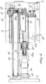
- the upper component 87 can be raised, lowered and locked in its closed position by means of any suitable actuation device, e.g. a fluid-operated device comprising a cylinder 80 designed to receive a working fluid, e.g. air or oil, which acts on a piston 81 slidably mounted in the cylinder and rigid with a stem 82.
- a fluid-operated device comprising a cylinder 80 designed to receive a working fluid, e.g. air or oil, which acts on a piston 81 slidably mounted in the cylinder and rigid with a stem 82.
- a dead hole 83 is provided along the unit defined by the stem 82 and the piston 81.
- a pin 84 has one end located in the hole 83 and its other end secured to a support 85 which is in turn fixed to the inner wall of the cylinder 80.
- a spring 86 is coiled in a spiral on the pin 84 and reacts against the bottom of the dead hole 83.
- the stem 82 is externally articulated to the upper component 87 by means of a connecting rod 88.
- the shoulders 95a are mutually joined at their bottom by a longitudinal crosspiece 99, rest on orientatable wheels 100 and have six protrusions 96 formed with seats 97 in which a hold 46 of a block-holding roller 12 can be received.
- One of the seats 97 is generally empty.
- the trolley 95 has coupling means for engagement with fixed abutment means, such as for example pins 101 arranged to engage with recesses provided in the longitudinal base 25 so as to removably block the roller supporting trolley in a fixed and precisely determined position with respect to the roller loading and unloading device.
- fixed abutment means such as for example pins 101 arranged to engage with recesses provided in the longitudinal base 25 so as to removably block the roller supporting trolley in a fixed and precisely determined position with respect to the roller loading and unloading device.
- a gib 102 fixed to the ground in a predetermined position with respect to said automatic loading and unloading device, has a lateral widening 103 and a horizontal widening 104 to facilitate the engagement operation of the trolley and keep it slightly raised so that it is prevented from moving during loading or unloading operations on and from the trolleys.
- Wheels 105 are adjustably fixed to the crosspiece 99 to obtain smooth sliding of the trolley on the gib 102.
- a gear 110 which is keyed on the hold of a block-holding roller 12, is in meshing engagement in a fixed reference position both with a lateral gear 111 rigid in rotation with the offset roller 11 and with a gear 112 of the screen roller 13.
- the gear 110 is provided with a reference mark 113 exactly at ninety degrees with respect to a spring-loaded dowel 114 which is provided with a spring 115 and can be remote controlled, e.g. by a fluid-operated system (not shown).
- the reference mark 113 is located at a cavity (between two teeth) of said gear 110, inside which a tooth of the gear 112, marked by a reference 116, must be arranged.
- the reference mark 116 is at ninety degrees with respect to a dowel 117 which can be remote controlled, e.g. by a fluid-operated system (not shown).
- the locked position reached by dowels 114 and 117 is detected by sensing means, e.g. by proximity devices (not shown).
- the angular excursion 118 of the offset roller 11 corresponds to the extension of a block located on the block-holding roller 12 and is related to said offset roller.
- Said angular excursion is measured by being converted into electric impulses by a coding device 119 arranged near to said gear 111, next to which there is provided a pulse detecting device 120.
- Micrometric adjustment, after presetting, is performed by means of a print position registration unit arranged inside the actuation unit 16 ( Figure 9).
- a gear 125 which can be operated by means of a handwheel (not illustrated) arranged outside the unit 16, acts on a pinion 126 which transmits its motion to a pivot 127 which is operatively connected to two feeding screws 15, 15a which move the block-holding roller 12 in contact with the offset roller.
- the pivot 127 has a mechanical limit switch 128 which, together with the pinion 126, delimits a detatching stroke 129.
- Positioning for printing is carried out by one motor (not illustrated in Figure 9) which, through a rod 121 connecting one shoulder of the flexographic machine to the other and a gear 130, simultaneously operates the four advancement screws 15, 15a designed to move sliding blocks 122, carrying the screen roller 13, and to move the saddles 123 carrying the block-holding roller 12.
- Each pair of feeding screws 15, 15a on the two shoulders of the machine is operatively connected to each other by means of a pair of gears 124 and is provided with locking elements 108.
- the contact-detatching sequence is performed by a piston 109 which moves the sliding block 122 and thus the saddle 123.
- FIG. 10 A device for locking the loading and unloading sequence of a block-holding roller in case of possible obstacles preventing it from being moved is illustrated in Figures 10 and 11, where the carriage 39, provided with wheels 40, has a disk-like spring 131 in its lower part, which urges a plate 132 coupled with a dowel 133.
- a bracket 135 is welded below the carriage 39 and has a proximity detector 134 connected to a safety system (not shown).
- the lateral shoulders 10 of a flexographic machine support a hold 46 of a block-holding roller which has a cylindrical portion 136 on both its sides. Adjacent to such a portion 136 there are two portions 137 having a greater diameter than said portion 136, so as to confine gripping means for said block-holding roller.
- the hold 46 has an outer ring 138 and a dead axial cavity 139 inside which the engagement unit 45 (not shown in Figure 12) can be received.
- the loading and unloading device While moving along the longitudinal guides 26, the loading and unloading device causes the upright 36 to rotate, the carriage 39 to slide along the upright and the sliding head 43 to move at right angle thereto, and moves near a block-holding roller to be replaced.
- the engagement unit 45 is then introduced in the end cavity 139 of the hold 46 of the block-holding roller and engages the roller only at one side thereof by means of the clamps 49.
- the roller 12 is then raised and, following a preset path, is gradually removed from its seat.
- the grip clamps 49 have been previously inclined, e.g. by 30 degrees, so as to cause the roller to rest on one clamp only, which is safer in that the roller is prevented from falling in case of accidental opening of the clamps.
- the sliding head or arm 43 then retracts in a direction parallel to the axis of the printing unit until it reaches a limit switch for the horizontal slider.
- the upright 36 then rotates about itself through 90 degrees, before moving on the carriage 28 in a direction normal to the axis of the drum 11 until it reaches the unloading position, where it further rotates on itself through 90 degrees.
- the loading and unloading device then unloads the roller on the trolley 95 and is ready to start a new loading or unloading operation, a loading operation comprising a reverse sequence of steps.
- presetting is performed by causing the roller 12 to rotate to a correct angular position, by means of the engagement unit 45, which can be rotated by a suitable electric motor (not illustrated).
- a computerized system checks the position of the offset roller 11 so that it has an angular excursion precisely defined by the specific block mounted on the block-holding roller as described above.
- the sliding head 43 of the automatic loading and unloading device retracts, the hydraulic caps 17 for retaining the block-holding roller are automatically closed, and the flexographic machine can start.
- the operation of the block-holding roller replacement can be effected at one, a few or all the printing units.
- Figures 13 and 14 show a modification of Figure 9 where a pair of double-acting cylinder-piston units 109 are arranged to operate the feeding screws 15 and 15a owing to the pressure applied by a pressure medium supplied to the inner space 150 and 151 in each cylinder of the cylinder piston units, so as to move a respective block-holding roller 12 and screen cylinder 13 in contact with, or away from, the offset roller 11 for a distance 129.
- a proximity detector 153 is removably kept in abutting engagement with a cap 154 by a limit switch 155 for the feeding screw 15, the cap 154 touching a support 156 for the proximity detector 153 by means of pins 157.
- a proximity detector 159 secured to a support 161, which is rigid with the pinion 126, and arranged to be touched by the screw end 160. If the block-holding roller 12 and the screen cylinder 13 are in a position of maximum distance from the offset roller 11, hydraulic pressure is applied in the spaces 151, so that the pistons 109 operate the screws 15 and the limit switch 155 is moved into abutting engagement with a thrust block 165.
- an overpressure is built up within the spaces 151 and a safety valve (not shown in the drawings), which is provided for each space 151 and is suitably set at a predetermined limit pressure, discharges a portion of fluid from its respective space 151, thereby allowing the screws 15 to move backwards, which results in the detectors 153 being moved away from their respective caps 154.
- the proximity detector 159 is energized to control an alarm system, e.g. a relay of a control unit arranged to stop the flexographic machine.
- the above described apparatus can be operated by one operator located at a control console to control the operations to be carried out by means of a computerized processing system.
Landscapes
- Engineering & Computer Science (AREA)
- Mechanical Engineering (AREA)
- Rotary Presses (AREA)
- Inking, Control Or Cleaning Of Printing Machines (AREA)
- Sheets, Magazines, And Separation Thereof (AREA)
- Coating Apparatus (AREA)
- Forklifts And Lifting Vehicles (AREA)
Claims (13)
- Mehrfarbige Flexodruckmaschine mit sternförmiger Struktur, die aufweist
zwei Lagerschultern (10),
eine Druckwalze oder Offsetwalze (10), die rotierbar in den Schultern (10) gehalten ist,
eine Vielzahl von Farbstationen, die winklig beabstandet um die Walze (11) herum angeordnet sind,
wobei jede Station einen Plattenzylinder (12) aufweist, der an die Offsetwalze (11) angrenzt,
ein Rasterzylinder (13), der vorgesehen ist, um Farbe von einer Ausziehwalze (14) oder von einer Abstreichklinge auf den Plattenzylinder (12) zu übertragen und der nahe an die oder weg von der Offsetwalze (11) bewegt werden kann,
eine Vorrichtung oder ein Roboter zum automatischen und aufeinanderfolgenden Beladen und Entladen der Plattenzylinder (12) auf und von den verschiedenen Farbstationen, und
Programmsteuermittel zum Steuern der Belade- und Entladevorrichtung,
dadurch gekennzeichnet, daß die Vorrichtung oder der Roboter aufweisen:
einen Trägerschlitten oder Wagen (28), der entlang Führungen (26), die sich parallel zu einer der Schultern (10) erstrecken, motorverfahrbar ist,
einen Ständer (36), der sich vom Trägerwagen (28) erstreckt und um eine vertikale Achse drehbar befestigt ist,
einen einziehbaren Arm (43), der vom Ständer (36) auskragt,
erste Betätigungsmittel (61) am Ständer (36), um den Arm einzuziehen oder zu längen, und
Greif- oder Klemmittel, die von dem Arm (43) getragen werden und aufweisen:
eine Zweibackenklemm- oder Zangeneinheit (49), die entfernbar angeordnet ist, um ein Halteelement (46) eines Plattenzylinders (12) in freitragender Art anzuheben,
einen auskragenden Zapfen (48), der drehbar in einen Hohlzylinder (62) eingesetzt ist und mit der ersten Backe der Klemm- oder Zangeneinheit (49) verbunden ist,
sowie der Hohlzylinder (62) mit der zweiten Backe der Klemm- oder Zangeneinheit (49) verbunden ist,
zweite Betätigungsmittel (65), die geeignet sind, den auskragenden Zapfen (48) in einer Richtung und den Hohlzylinder in einer entgegengesetzten Richtung zu drehen,
Eingriffsmittel (45), die parallel zum Hohlzylinder (62) angeordnet sind und bestimmt sind, in einen stirnseitigen Hohlraum (139) des Halteelementes (46) des Plattenzylinders (12) einzugreifen. - Maschine nach Anspruch 1, dadurch gekennzeichnet, daß jede Farbstation aufweist, zwei Haltekappen (17) für jeden Plattenzylinder (12), wobei jede Haltekappe (17) so gestaltet ist, daß sie ein entsprechendes Halteelement (46) des Plattenzylinders (12) hält, so daß er sich drehen kann, ferner Betätigungsmittel (80, 81, 82), die angeordnet sind, um die Kappen (17) automatisch zu öffnen und zu schließen, für das automatische Ersetzen der Plattenzylinder (12).
- Maschine nach Anspruch 2, dadurch gekennzeichnet, daß jede Haltekappe (17) an einem Ende in einem Zapfen (89) schwenkbar ist, so daß sie zwischen einer geschlossenen Stellung und einer geöffneten Stellung geschwenkt werden kann, um dessen entsprechenden Plattenzylinder (12) in Position zu bringen oder zu entfernen.
- Maschine nach Anspruch 1, dadurch gekennzeichnet, daß die Klemm- oder Zangeneinheit Betätigungsmittel (71) aufweist, um die Klemm- oder Zangeneinheit bezüglich einer vertikalen Ebene zu neigen, um sicherzustellen, daß sich der Plattenzylinder (12) vorwiegend auf einem einzigen Backen der Klemm- oder Zangeneinheit aufstützt.
- Maschine nach Anspruch 1, dadurch gekennzeichnet, daß die Eingriffsmittel (45) aufweisen, mindestens einen Bolzen, zum Eingriff in eine axiale Sacklochaufnahme (139), die in jedem Haltelement (46) des Plattenzylinders (12) vorgesehen ist, und mindestens einen berührungslosen Grenztaster (47), der geeignet ist, die Kupplung zwischen dem Bolzen und der Aufnahme zu erfassen, um die Klemmeinheit zu betätigen.
- Maschine nach Anspruch 5, dadurch gekennzeichnet, daß der Bolzen (45) rotierbar mit dem einziehbaren Arm (43) verbunden und beweglich mit Betätigungsmitteln (71) verbunden ist.
- Maschine nach einem vorstehenden Anspruch, dadurch gekennzeichnet, daß die automatische Belade- und Entladevorrichtung aufweist, ein am Boden oder an der Decke befestigtes, längsverlaufendes Schlittengestell (25) mit Führungen (26), in die ein Wagen (28) beweglich eingesetzt ist, eine Getriebemotor-(32) und Schneckenantrieb-(34)-einrichtung, die geeignet ist, die Bewegung auf den wagen (28) zu übertragen, eine zentrale Platte (55), die vom Wagen (28) getragen wird und den Ständer (36) trägt, und einen Motor (37), der mit einem Getriebe (53) versehen ist, um die zentrale Platte (55) drehen zu können.
- Maschine nach einem oder mehreren der vorstehenden Ansprüche, dadurch gekennzeichnet, daß der Ständer (36) aufweist, einen Drehzapfen (35), auf dem der Ständer (36) um eine vertikale Achse drehen kann, einen Schlitten oder Wagen (39), der parallel zur Rotationsachse des Drehzapfens (35) verschiebbar angebracht ist und den einziehbaren Arm trägt, und Betätigungsmittel (42) für die Verschiebebewegung des Schlittens oder Wagens (39).
- Maschine nach einem vorstehenden Anspruch, dadurch gekennzeichnet, daß der einziehbare Arm aufweist, einen Kopf (43), horizontale Verschiebeführungen (41), entlang denen der Kopf verschoben werden kann, wobei der Kopf (43) die Backenklemmen (49) und die Eingriffsmittel (45) des Halteelementes (46) des Plattenzylinders (12) trägt, und die ersten Betätigungsmittel in Art einer fluidbetriebenen Einheit (61) zum Verschieben des Kopfes (43).
- Maschine nach einem vorstehenden Anspruch, dadurch gekennzeichnet, daß sie einen Walzentragwagen (95) aufweist, der Kupplungsmittel (101) zum aufhebbaren Blockieren in einer bleibenden Bezugsposition bezüglich des Ständers (36) aufweist.
- Maschine nach einem vorstehenden Anspruch, dadurch gekennzeichnet, daß die Programmsteuermittel aufweisen, einen Computer, der vorgesehen ist, um eine winklige Auslenkung des Plattenzylinders (12), nachdem dieser auf der Farbstation untergebracht ist, zu bewirken, Kupplungsbolzen (114, 117) die geeignet sind, jeden Plattenzylinder (12) und den entsprechenden Rasterzylinder (13) in einer korrekten Winkelposition zu arretieren, Zahnräder (110), die mit dem Plattenzylinder (12) verkeilt sind und Zahnräder (112), die mit dem entsprechenden Rasterzylinder (13) verkeilt sind, eine Vorrichtung (119) zum Umwandeln der Winkeldrehbewegung der Offsetwalze (11) und eine Vorrichtung (120) zum Messen der Winkeldrehbewegung, dabei die Winkelbewegungen steuernd, um so den Farbdruckstock in jeder Farbstation gemäß den vom Programm gesetzten Winkelwerten ausfindig zu machen.
- Maschine nach einem vorstehenden Anspruch, dadurch gekennzeichnet, daß sie aufweist, eine Kompensationsvorrichtung, die geeignet ist, die abschließende Korrektur für das Drucken auszuführen, durch drehende mikrometrische Zuführschrauben (15, 15a) zum Justieren des Abstandes zwischen einem Plattenzylinder (12) und der Offsetwalze (11).
- Maschine nach Anspruch 12, dadurch gekennzeichnet, daß sie aufweist, ein Sicherheitssystem mit mindestens einer fluidbetriebenen Zylinder-Kolben-Einheit (109), um die Zuführschrauben (15, 15a) zu betreiben, um für eine relativ kurze Entfernung einen entsprechenden Plattenzylinder (12) und in Kontakt befindliche Rasterzylinder (13) zu bewegen, oder davon weg die Offsetwalze (11), ein Sicherheitsventil, um Fluid von der fluidbetriebenen Zylinder-Kolben-Einheit (109) auszugeben, wenn der Fluiddruck darin einen vorgegebenen Höchstdruck überschreitet, und schließlich einen berührungslosen Grenztaster (153, 159), um die Position der Zuführschrauben (15, 15a) zu erfassen.
Applications Claiming Priority (2)
| Application Number | Priority Date | Filing Date | Title |
|---|---|---|---|
| IT8494089 | 1989-06-02 | ||
| IT8984940A IT1234647B (it) | 1989-06-02 | 1989-06-02 | Macchina flexografica a piu' colori con dispositivo per il carico e lo scarico automatico dei cilindri portacliche' |
Publications (3)
| Publication Number | Publication Date |
|---|---|
| EP0400517A2 EP0400517A2 (de) | 1990-12-05 |
| EP0400517A3 EP0400517A3 (de) | 1991-05-08 |
| EP0400517B1 true EP0400517B1 (de) | 1996-03-13 |
Family
ID=11326144
Family Applications (1)
| Application Number | Title | Priority Date | Filing Date |
|---|---|---|---|
| EP90110049A Expired - Lifetime EP0400517B1 (de) | 1989-06-02 | 1990-05-28 | Mehrfarbige Flexodruckmaschine mit einer Vorrichtung zum automatischen Auf- und Abladen von Plattenzylindern |
Country Status (8)
| Country | Link |
|---|---|
| US (1) | US5010813A (de) |
| EP (1) | EP0400517B1 (de) |
| JP (1) | JP2858163B2 (de) |
| AT (1) | ATE135288T1 (de) |
| CA (1) | CA2018063C (de) |
| DE (1) | DE69025798T2 (de) |
| ES (1) | ES2086330T3 (de) |
| IT (1) | IT1234647B (de) |
Cited By (1)
| Publication number | Priority date | Publication date | Assignee | Title |
|---|---|---|---|---|
| US7409909B2 (en) | 2003-02-12 | 2008-08-12 | Windmoeller & Hoelscher Kg | Method for replacing printing sleeves in a printing press |
Families Citing this family (18)
| Publication number | Priority date | Publication date | Assignee | Title |
|---|---|---|---|---|
| US5282418A (en) * | 1991-03-13 | 1994-02-01 | Tokyo Kikai Seisakusho, Ltd. | Roller changer |
| US5370047A (en) * | 1993-12-01 | 1994-12-06 | Paper Converting Machine Company | Flexographic press adapted for short runs and method |
| CN1074993C (zh) * | 1994-01-19 | 2001-11-21 | 德电株式会社 | 感应加热的滚筒装置 |
| ES2128892B1 (es) * | 1995-04-28 | 2000-01-16 | Comexi Sa | Maquina para la impresion flexografica en varios colores con prerregistro automatico de impresion de los distintos colores. |
| DE19519141A1 (de) * | 1995-05-30 | 1996-12-05 | Fischer & Krecke Gmbh & Co | Flexodruckmaschine mit variabler Drucklänge |
| IT1299666B1 (it) † | 1998-05-05 | 2000-03-24 | Uteco Spa Roto Flexo & Convert | Macchina rotativa flessografica a tamburo centrale a piu' colori |
| US6038972A (en) | 1998-12-29 | 2000-03-21 | Paper Converting Machine Company | Quick change system for a press |
| DE19962425B4 (de) * | 1999-12-22 | 2004-01-29 | Man Roland Druckmaschinen Ag | Vorrichtung zum Wechseln eines rotationssymetrischen Bauteiles |
| US6289811B1 (en) * | 2000-01-11 | 2001-09-18 | Paper Converting Machine Co. | Method and apparatus for sampling and inspecting ink for a printing press |
| IT1314445B1 (it) * | 2000-10-18 | 2002-12-13 | Flavio Buffo | Gruppo colore flessografico con regolazione centralizzata del registroe della pressione di stampa. |
| US7114447B2 (en) * | 2002-03-20 | 2006-10-03 | Comexi, S.A. | Flexographic printer with enclosures at a regulated temperature and vapor extraction |
| US6918338B2 (en) * | 2003-01-30 | 2005-07-19 | Hewlett-Packard Development Company, L.P. | Printing system |
| DE102008025995B4 (de) * | 2008-05-29 | 2012-12-06 | Windmöller & Hölscher Kg | Vorrichtung zum Erfassen eines Farbe führenden Zylinders einer Druckmaschine |
| DE102008025996A1 (de) * | 2008-05-29 | 2009-12-24 | Windmöller & Hölscher Kg | Druckmaschine mit mehreren Farbwerken |
| US20100122638A1 (en) * | 2008-11-18 | 2010-05-20 | C.G. Bretting Manufacturing Co., Inc. | Flexographic Printing Apparatus And Method |
| US9186799B2 (en) | 2011-07-13 | 2015-11-17 | Brooks Automation, Inc. | Compact direct drive spindle |
| JP6307267B2 (ja) * | 2013-12-25 | 2018-04-04 | アイマー・プランニング株式会社 | 印刷機 |
| CN105346211B (zh) * | 2015-11-30 | 2018-09-21 | 深圳市全印图文技术有限公司 | 一种用于消除布匹褶皱的进布装置与印花机 |
Family Cites Families (8)
| Publication number | Priority date | Publication date | Assignee | Title |
|---|---|---|---|---|
| FR1374433A (fr) * | 1963-08-08 | 1964-10-09 | Stafford Printers Inc | Dispositif et méthode pour l'impression |
| US3789757A (en) * | 1971-03-26 | 1974-02-05 | Motter J Printing Press Co | Printing press having automatic printing cylinder loading and unloading apparatus |
| US3760956A (en) * | 1971-08-23 | 1973-09-25 | Burch Controls Inc | Industrial robot |
| US3876087A (en) * | 1973-05-22 | 1975-04-08 | Francesco Osta | Removable cylinder carrying carriage, for rotary machines for the treatment of band material |
| DE2632455C3 (de) * | 1976-07-19 | 1979-05-23 | Windmoeller & Hoelscher, 4540 Lengerich | Vorrichtung zum Ein- und Ausfahren des Farbwerkes und des Formzylinders einer Rotations-Tiefdruckmaschine |
| FR2485990A1 (fr) * | 1980-07-03 | 1982-01-08 | Holweg Const Mec | Dispositif pour le changement automatique de cylindres d'une imprimeuse flexographique |
| JPS60244556A (ja) * | 1984-05-17 | 1985-12-04 | Rengo Co Ltd | 多色刷輪転印刷機の版胴交換装置 |
| DE3738973C1 (de) * | 1987-11-17 | 1989-05-18 | Kleinewefers Gmbh | Vorrichtung zum Auswechseln elastischer Superkalander-Walzen |
-
1989
- 1989-06-02 IT IT8984940A patent/IT1234647B/it active
-
1990
- 1990-05-28 EP EP90110049A patent/EP0400517B1/de not_active Expired - Lifetime
- 1990-05-28 ES ES90110049T patent/ES2086330T3/es not_active Expired - Lifetime
- 1990-05-28 AT AT90110049T patent/ATE135288T1/de not_active IP Right Cessation
- 1990-05-28 DE DE69025798T patent/DE69025798T2/de not_active Expired - Fee Related
- 1990-05-29 US US07/529,426 patent/US5010813A/en not_active Expired - Lifetime
- 1990-06-01 JP JP2141718A patent/JP2858163B2/ja not_active Expired - Lifetime
- 1990-06-01 CA CA002018063A patent/CA2018063C/en not_active Expired - Fee Related
Cited By (1)
| Publication number | Priority date | Publication date | Assignee | Title |
|---|---|---|---|---|
| US7409909B2 (en) | 2003-02-12 | 2008-08-12 | Windmoeller & Hoelscher Kg | Method for replacing printing sleeves in a printing press |
Also Published As
| Publication number | Publication date |
|---|---|
| IT1234647B (it) | 1992-05-26 |
| ES2086330T3 (es) | 1996-07-01 |
| JPH0396350A (ja) | 1991-04-22 |
| DE69025798D1 (de) | 1996-04-18 |
| CA2018063A1 (en) | 1990-12-02 |
| CA2018063C (en) | 1999-11-09 |
| DE69025798T2 (de) | 1996-08-01 |
| EP0400517A3 (de) | 1991-05-08 |
| EP0400517A2 (de) | 1990-12-05 |
| IT8984940A0 (it) | 1989-06-02 |
| JP2858163B2 (ja) | 1999-02-17 |
| ATE135288T1 (de) | 1996-03-15 |
| US5010813A (en) | 1991-04-30 |
Similar Documents
| Publication | Publication Date | Title |
|---|---|---|
| EP0400517B1 (de) | Mehrfarbige Flexodruckmaschine mit einer Vorrichtung zum automatischen Auf- und Abladen von Plattenzylindern | |
| EP2388155B1 (de) | Vorrichtung und Verfahren zur Änderung der Drehwinkellage eines Luftreifens auf einer Felge | |
| US5876501A (en) | Wheel soaping apparatus | |
| US12544916B2 (en) | Apparatus for automatically replacing printing sleeves | |
| CA1233623A (en) | Apparatus for the handling of metal sheets | |
| CA3208183A1 (en) | Apparatus for automatically replacing printing sleeves | |
| US4614265A (en) | Apparatus for automatically splitting transfer feed rails in a transfer feed press | |
| DD242648A5 (de) | Verfahren und vorrichtung zum herstellen von verlitztem stranggut mit hilfe einer dooppelschlagverlitzmaschine | |
| DE2145929C3 (de) | Vorrichtung zur Herstellung von Schalenformen für PräzfsionsguB | |
| DE69404552T2 (de) | Vorrichtung zum Abkratzen von Reifen, mit regelbarer relativer Positionierung der Reifens und des Werkzeuges | |
| GB2169233A (en) | Piercing press and tool holders for use therein | |
| DE19825922C2 (de) | Linsenrad-Schleifmaschine | |
| IE45736B1 (en) | Improvements in tyre building machinery | |
| JP2010194988A (ja) | ロータリースクリーン装置 | |
| DE4202803C1 (en) | Method of removing tyres from wheel rims - has arms squeezing beam into wheel well controlled using arm force, arm position and wheel torque sensors | |
| US5161464A (en) | Block sleeve assembly device | |
| DE4132827A1 (de) | Verfahren und vorrichtung zum verspannen, aufblasen und abkuehlen von vulkanisierten reifen | |
| EP1318015B1 (de) | Drucksatz für schnellen Hülsenwechsel in flexographischen Druckmaschinen | |
| US4506424A (en) | Automated railroad bearing handling machine | |
| JP2626786B2 (ja) | グラビア輪転機の版胴交換着脱方法および装置 | |
| EP4275875B1 (de) | Anlage zur vermessung von reifen sowie zugehöriges betriebsverfahren | |
| US2999403A (en) | Axle recentering machine | |
| JPH05150047A (ja) | 遠隔スミヤ装置 | |
| US4627884A (en) | Method of and apparatus for applying looped rubber member onto tire building drum | |
| EP0427668A1 (de) | Crimpmaschine |
Legal Events
| Date | Code | Title | Description |
|---|---|---|---|
| PUAI | Public reference made under article 153(3) epc to a published international application that has entered the european phase |
Free format text: ORIGINAL CODE: 0009012 |
|
| AK | Designated contracting states |
Kind code of ref document: A2 Designated state(s): AT BE CH DE ES FR GB GR IT LI SE |
|
| PUAL | Search report despatched |
Free format text: ORIGINAL CODE: 0009013 |
|
| AK | Designated contracting states |
Kind code of ref document: A3 Designated state(s): AT BE CH DE ES FR GB GR IT LI SE |
|
| 17P | Request for examination filed |
Effective date: 19911017 |
|
| 17Q | First examination report despatched |
Effective date: 19940128 |
|
| RAP3 | Party data changed (applicant data changed or rights of an application transferred) |
Owner name: UTECO S.P.A. FLEXO & CONVERTING MACHINERY |
|
| GRAA | (expected) grant |
Free format text: ORIGINAL CODE: 0009210 |
|
| AK | Designated contracting states |
Kind code of ref document: B1 Designated state(s): AT BE CH DE ES FR GB GR IT LI SE |
|
| PG25 | Lapsed in a contracting state [announced via postgrant information from national office to epo] |
Ref country code: GR Free format text: LAPSE BECAUSE OF FAILURE TO SUBMIT A TRANSLATION OF THE DESCRIPTION OR TO PAY THE FEE WITHIN THE PRESCRIBED TIME-LIMIT Effective date: 19960313 Ref country code: FR Effective date: 19960313 Ref country code: BE Effective date: 19960313 Ref country code: AT Effective date: 19960313 |
|
| REF | Corresponds to: |
Ref document number: 135288 Country of ref document: AT Date of ref document: 19960315 Kind code of ref document: T |
|
| REF | Corresponds to: |
Ref document number: 69025798 Country of ref document: DE Date of ref document: 19960418 |
|
| ITF | It: translation for a ep patent filed | ||
| PG25 | Lapsed in a contracting state [announced via postgrant information from national office to epo] |
Ref country code: SE Effective date: 19960613 |
|
| REG | Reference to a national code |
Ref country code: ES Ref legal event code: FG2A Ref document number: 2086330 Country of ref document: ES Kind code of ref document: T3 |
|
| EN | Fr: translation not filed | ||
| PLBE | No opposition filed within time limit |
Free format text: ORIGINAL CODE: 0009261 |
|
| STAA | Information on the status of an ep patent application or granted ep patent |
Free format text: STATUS: NO OPPOSITION FILED WITHIN TIME LIMIT |
|
| 26N | No opposition filed | ||
| REG | Reference to a national code |
Ref country code: GB Ref legal event code: IF02 |
|
| PGFP | Annual fee paid to national office [announced via postgrant information from national office to epo] |
Ref country code: GB Payment date: 20040525 Year of fee payment: 15 |
|
| PGFP | Annual fee paid to national office [announced via postgrant information from national office to epo] |
Ref country code: ES Payment date: 20040526 Year of fee payment: 15 |
|
| PGFP | Annual fee paid to national office [announced via postgrant information from national office to epo] |
Ref country code: CH Payment date: 20040629 Year of fee payment: 15 |
|
| PGFP | Annual fee paid to national office [announced via postgrant information from national office to epo] |
Ref country code: DE Payment date: 20040722 Year of fee payment: 15 |
|
| PG25 | Lapsed in a contracting state [announced via postgrant information from national office to epo] |
Ref country code: IT Free format text: LAPSE BECAUSE OF NON-PAYMENT OF DUE FEES;WARNING: LAPSES OF ITALIAN PATENTS WITH EFFECTIVE DATE BEFORE 2007 MAY HAVE OCCURRED AT ANY TIME BEFORE 2007. THE CORRECT EFFECTIVE DATE MAY BE DIFFERENT FROM THE ONE RECORDED. Effective date: 20050528 Ref country code: GB Free format text: LAPSE BECAUSE OF NON-PAYMENT OF DUE FEES Effective date: 20050528 |
|
| PG25 | Lapsed in a contracting state [announced via postgrant information from national office to epo] |
Ref country code: ES Free format text: LAPSE BECAUSE OF NON-PAYMENT OF DUE FEES Effective date: 20050530 |
|
| PG25 | Lapsed in a contracting state [announced via postgrant information from national office to epo] |
Ref country code: LI Free format text: LAPSE BECAUSE OF NON-PAYMENT OF DUE FEES Effective date: 20050531 Ref country code: CH Free format text: LAPSE BECAUSE OF NON-PAYMENT OF DUE FEES Effective date: 20050531 |
|
| PG25 | Lapsed in a contracting state [announced via postgrant information from national office to epo] |
Ref country code: DE Free format text: LAPSE BECAUSE OF NON-PAYMENT OF DUE FEES Effective date: 20051201 |
|
| GBPC | Gb: european patent ceased through non-payment of renewal fee |
Effective date: 20050528 |
|
| REG | Reference to a national code |
Ref country code: CH Ref legal event code: NV Representative=s name: ROTTMANN, ZIMMERMANN + PARTNER AG |
|
| REG | Reference to a national code |
Ref country code: ES Ref legal event code: FD2A Effective date: 20050530 |