EP0400351A1 - Process and device for firing tubes, especially ceramic tubes, preferably externally glazed drainage pipes having sleeves - Google Patents
Process and device for firing tubes, especially ceramic tubes, preferably externally glazed drainage pipes having sleeves Download PDFInfo
- Publication number
- EP0400351A1 EP0400351A1 EP90108440A EP90108440A EP0400351A1 EP 0400351 A1 EP0400351 A1 EP 0400351A1 EP 90108440 A EP90108440 A EP 90108440A EP 90108440 A EP90108440 A EP 90108440A EP 0400351 A1 EP0400351 A1 EP 0400351A1
- Authority
- EP
- European Patent Office
- Prior art keywords
- support
- pipes
- roller
- rollers
- stoneware
- Prior art date
- Legal status (The legal status is an assumption and is not a legal conclusion. Google has not performed a legal analysis and makes no representation as to the accuracy of the status listed.)
- Withdrawn
Links
Images


Classifications
-
- F—MECHANICAL ENGINEERING; LIGHTING; HEATING; WEAPONS; BLASTING
- F27—FURNACES; KILNS; OVENS; RETORTS
- F27B—FURNACES, KILNS, OVENS, OR RETORTS IN GENERAL; OPEN SINTERING OR LIKE APPARATUS
- F27B9/00—Furnaces through which the charge is moved mechanically, e.g. of tunnel type; Similar furnaces in which the charge moves by gravity
- F27B9/14—Furnaces through which the charge is moved mechanically, e.g. of tunnel type; Similar furnaces in which the charge moves by gravity characterised by the path of the charge during treatment; characterised by the means by which the charge is moved during treatment
- F27B9/20—Furnaces through which the charge is moved mechanically, e.g. of tunnel type; Similar furnaces in which the charge moves by gravity characterised by the path of the charge during treatment; characterised by the means by which the charge is moved during treatment the charge moving in a substantially straight path tunnel furnace
- F27B9/201—Furnaces through which the charge is moved mechanically, e.g. of tunnel type; Similar furnaces in which the charge moves by gravity characterised by the path of the charge during treatment; characterised by the means by which the charge is moved during treatment the charge moving in a substantially straight path tunnel furnace walking beam furnace
- F27B9/208—Furnaces through which the charge is moved mechanically, e.g. of tunnel type; Similar furnaces in which the charge moves by gravity characterised by the path of the charge during treatment; characterised by the means by which the charge is moved during treatment the charge moving in a substantially straight path tunnel furnace walking beam furnace the workpieces being rotated during their advance
-
- B—PERFORMING OPERATIONS; TRANSPORTING
- B65—CONVEYING; PACKING; STORING; HANDLING THIN OR FILAMENTARY MATERIAL
- B65G—TRANSPORT OR STORAGE DEVICES, e.g. CONVEYORS FOR LOADING OR TIPPING, SHOP CONVEYOR SYSTEMS OR PNEUMATIC TUBE CONVEYORS
- B65G35/00—Mechanical conveyors not otherwise provided for
-
- F—MECHANICAL ENGINEERING; LIGHTING; HEATING; WEAPONS; BLASTING
- F27—FURNACES; KILNS; OVENS; RETORTS
- F27B—FURNACES, KILNS, OVENS, OR RETORTS IN GENERAL; OPEN SINTERING OR LIKE APPARATUS
- F27B9/00—Furnaces through which the charge is moved mechanically, e.g. of tunnel type; Similar furnaces in which the charge moves by gravity
- F27B9/14—Furnaces through which the charge is moved mechanically, e.g. of tunnel type; Similar furnaces in which the charge moves by gravity characterised by the path of the charge during treatment; characterised by the means by which the charge is moved during treatment
- F27B9/20—Furnaces through which the charge is moved mechanically, e.g. of tunnel type; Similar furnaces in which the charge moves by gravity characterised by the path of the charge during treatment; characterised by the means by which the charge is moved during treatment the charge moving in a substantially straight path tunnel furnace
- F27B9/24—Furnaces through which the charge is moved mechanically, e.g. of tunnel type; Similar furnaces in which the charge moves by gravity characterised by the path of the charge during treatment; characterised by the means by which the charge is moved during treatment the charge moving in a substantially straight path tunnel furnace being carried by a conveyor
- F27B9/2407—Furnaces through which the charge is moved mechanically, e.g. of tunnel type; Similar furnaces in which the charge moves by gravity characterised by the path of the charge during treatment; characterised by the means by which the charge is moved during treatment the charge moving in a substantially straight path tunnel furnace being carried by a conveyor the conveyor being constituted by rollers (roller hearth furnace)
- F27B9/2415—Furnaces through which the charge is moved mechanically, e.g. of tunnel type; Similar furnaces in which the charge moves by gravity characterised by the path of the charge during treatment; characterised by the means by which the charge is moved during treatment the charge moving in a substantially straight path tunnel furnace being carried by a conveyor the conveyor being constituted by rollers (roller hearth furnace) the charge rotating about an axis transversal to the axis of advancement of the charge
-
- F—MECHANICAL ENGINEERING; LIGHTING; HEATING; WEAPONS; BLASTING
- F27—FURNACES; KILNS; OVENS; RETORTS
- F27B—FURNACES, KILNS, OVENS, OR RETORTS IN GENERAL; OPEN SINTERING OR LIKE APPARATUS
- F27B9/00—Furnaces through which the charge is moved mechanically, e.g. of tunnel type; Similar furnaces in which the charge moves by gravity
- F27B9/30—Details, accessories, or equipment peculiar to furnaces of these types
- F27B9/36—Arrangements of heating devices
-
- F—MECHANICAL ENGINEERING; LIGHTING; HEATING; WEAPONS; BLASTING
- F27—FURNACES; KILNS; OVENS; RETORTS
- F27D—DETAILS OR ACCESSORIES OF FURNACES, KILNS, OVENS, OR RETORTS, IN SO FAR AS THEY ARE OF KINDS OCCURRING IN MORE THAN ONE KIND OF FURNACE
- F27D3/00—Charging; Discharging; Manipulation of charge
- F27D3/02—Skids or tracks for heavy objects
- F27D3/026—Skids or tracks for heavy objects transport or conveyor rolls for furnaces; roller rails
Definitions
- the invention relates to a method and a device for firing pipes, in particular ceramic pipes, preferably of sewer stoneware pipes with sleeves, glazed inside and outside, using the rapid firing method.
- Stoneware pipes with a sleeve, the z. B. used for the construction of a sewer system are usually driven upright on tunnel kiln cars through a tunnel kiln and burned.
- a stoneware pipe stays in the furnace for a very long time; it is usually 30 to 50 hours.
- Stoneware pipes are made of ceramic material that has been solidified by drying and firing a mass of ceramic raw materials. The ceramic mass shrinks as it dries and burns. The solidification takes place via a sintering process in which the material gets into a plastic state. The drying and burning must therefore be carried out very carefully.
- Stoneware pipes are also glazed on the outside and preferably also on the inside.
- the glaze material forms a viscous melt during firing, which should result in a tight, solid glass phase coating after cooling.
- the stoneware pipes must not come into contact with one another or with other objects during the melting phase formation, because otherwise the glueing or the glaze could be disturbed, so that the stoneware pipe would become unusable.
- the known method requires high energy costs, because the tunnel kiln cars in particular absorb heat that is lost. In addition, numerous operations are required.
- the pipe ends can e.g. B. become out of round or even tear, which can result in an unusable, faulty stoneware pipe.
- the permissible shaft deflection can be exceeded.
- the heat energy distribution in the tunnel kiln can be inhomogeneous. This results in particular from the fact that the stoneware pipes are placed as close as possible on a tunnel kiln car that the fuel gases cannot apply heat energy evenly to each pipe, which can result in so-called weak fire or overburned, deformed material, which can lead to rejects.
- the transition zone between the pipe and the sleeve, via which the load of the pipe is conducted into the sleeve is critical. If this zone is not optimally supplied with thermal energy, tensions can occur in this area during firing, which lead to cracks and render the pipe unusable.
- DE-OS 29 21 200 describes a process for the production of cylindrical, ceramic pipes with which better economy is to be ensured and also to ensure that the roundness of the pipes is preserved.
- the pipes are transported lying through the preheating zone and lying and rolling through the burning zone and lying through the cooling zone.
- Rod-shaped sliders and supports, which must touch the pipes, are used as transport means with endless chains.
- this is not feasible for glazed pipes because the glaze is damaged, especially if the pipes rotate, as intended in the main combustion zone.
- the pipes also roll on a ramp surface, so that a molten, sticky glaze would be partially removed from the ramp surface.
- the ramp is designed to ensure that the pipes do not sag when fired in a viscous state. If the pipes have sleeves, they should hang laterally over the rolling surface.
- the rotation of the pipes is very slow, depending on the transport speed, so that the pipe ends passing the burners are overheated in a punctiform manner.
- the wall of the ramp should protect the transport chains against inadmissible heat by simply pushing the slides through a slot in the wall of the ramp.
- the slots allow too much heat to pass through, so that the function of the transport chain is jeopardized. Due to chain elongation due to thermal expansion and joint wear, the cycle path from burner to burner becomes imprecise. This method, which has been known for a long time, has so far not been implemented because of the disadvantages mentioned, for the manufacture of sewer stoneware pipes with sleeves on both sides.
- European patent 0 131 955 describes a method for firing ceramic tubes in a roller hearth furnace, in which the tubes are transported through the furnace lying on circular disks of support rollers.
- the support rollers are included rotated a peripheral speed that can be controlled independently of the transport speed, so that the tubes lying on the circular disks are rotated, namely at a preselectable speed.
- Transport is interrupted in the sintering zone, but the pipes' own rotation is maintained.
- roller hearth furnaces described A particular disadvantage of the known roller hearth furnaces described is that the carrying and supporting device is transported through the firing zone, heats up in the process and is cooled again when it leaves the firing zone. This means that it is exposed to considerable changes in temperature and must be designed accordingly in terms of material and construction.
- roller hearth furnaces In addition to the roller hearth furnaces, the carrying and supporting devices of which are transported, kilns with a fixed stationary roller conveyor but rotating rollers are also known (DE-OS 29 47 540, DE-OS 33 01 660).
- the rotation of the rollers causes the transport of the ceramic material to be fired, e.g. B. of wall panels or tiles.
- the rollers designed as tubes should have elevations and depressions, so that there are star-shaped tubes in cross section. The objects to be burned then lie only on the elevations, as a result of which the contact area between the underside of the object to be burned and the rollers is greatly reduced.
- a heating cabinet with a transport device is known, with which pipes are transported through the heating cabinet with tubular rods under their own rotation.
- the angular displacement of the crank pin is chosen so that the rods form a support device with a sinusoidal path. Due to the constant rotation of the crankshafts, the support device formed by the rods with sinusoidal gear changes progressively while maintaining the same cycle and the same amplitude. This results in a superimposed translational rotational movement of the tubes.
- the roller furnace 1 is equipped with a roller conveyor 9, which has a plurality of rollers 10, which are arranged in the longitudinal direction of the furnace at the same distance from one another and are stationarily mounted in one plane, preferably in a horizontal plane.
- the roller conveyor 9 is spaced above the furnace floor 3 and divides the furnace interior 11 into an upper combustion chamber 12 and a lower furnace chamber 13; it thus extends in the longitudinal direction of the furnace from the rear wall 6 to the front wall 7.
- rollers 10 pass through corresponding holes in the side walls 4, 5, their roller dies 10 a, 10 b protruding from the furnace 1 and carrying coupling elements 16 for a drive means 17 a, 17 b.
- Suitable is any drive means which, according to the invention, the rollers 10 simultaneously, uniformly and in the same direction, ie with the same direction of rotation, about their longitudinal axis 10 c drives, wherein one of the drive means 17 a (or 17 b) generates a specific direction of rotation 18 (or 19) and the other drive means 17 b (or 17 a) generates the opposite direction of rotation 19 (or 18).
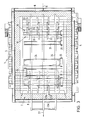
- the roller 10 is constructed, for example, from a roller tube 20, in the end regions of which stub shafts 21 are inserted (FIG. 4). It is essential that the roller tubes in the section lying in the interior of the furnace 11 are equipped with support disks 23 as support elements for the objects to be burned, which are mounted on the respective roller tube 20 in a rotationally fixed manner. A plurality of support disks 23 are arranged on a roller tube 20 at a distance from one another, preferably at the same distance. Each roll 10 of the roller furnace according to FIGS. 1 to 3 carry z. B. four support disks 23; 4 carries only three support disks 23. The number of support disks depends on the weight to be carried.
- Stoneware pipes 24 having sleeves 25 are shown as objects to be carried and burned, for which the roller furnace according to the invention can be used in particular.
- the roller furnace according to the invention can be used for stoneware pipes 24 of different diameters, as shown in FIG. 3.
- the pipes are preferably alternately arranged in succession, ie one vitrified clay pipe with the sleeve 25 facing the side wall 4 and the following with the sleeve 25 facing the side wall 5 on the support disks 23.
- the diameter of the support disk is chosen so large that a distance remains between the sleeve 25 of a stoneware pipe 24 and the outer surface of a roller pipe 20 and the sleeve is arranged laterally between the respective side wall 4 or 5 and the last support disk 23 on the outside (see FIG 4).
- the distance between adjacent roller tubes 20 from each other in the roller conveyor 9 and the diameter of the support discs 23 are chosen so that the circumferential ring surface 23 a of a support disc is only a short distance from the outer surface 20 a of the two adjacent roller tubes 20, so that the surfaces Do not touch 20 a and 23 a.
- the support disks 23 b of a roller tube 20 b adjacent to a specific roller tube 20 b are laterally offset from the support disks 23 of the one particular roller tube 20 such that the support disks 23 and 23 b overlap laterally.
- the radius R of the support disk 23, 23 b is accordingly greater than half the distance A between two adjacent roller tubes 20 (FIG. 5), so that an overlap region 26 results.
- the lateral offset is chosen to be as small as possible so that the width B of a row of support disks 23 c resulting from the offset remains as small as possible (FIG. 4).
- a support disk row 23 c thus results from the support disk row 23 d, which is formed from the support disks 23 arranged one behind the other in the longitudinal direction or transport direction 27 (FIG. 3), each of which sits on each roller tube 20 after the next, and the support disk row 23 e, which is formed from the support disks 23 b arranged one behind the other in the transport direction 27 and which are seated on the roller tubes 20 b arranged between the roller tubes 20, one after the other.
- the tubular shafts 24 a of the tubes 24 are supported.
- the tubes 24 are rotated in the opposite direction of rotation 29 (Fig. 6). Since the support disks 23, 23 b can also be driven in the direction of rotation 18, the tubes 24 can also be rotated in the direction of rotation 30 opposite to the direction of rotation 29 (FIG. 5).
- the objects which are to be burned and lie transversely to the transport direction 27 are transported in translation with the stationary support disks 23, 23 b in or against the transport direction 27.
- the support disks are designed as segment support disks and have z. B. tendon segment sections 31, from which straight tendon support edges 32, 32 b result, the tendon support edge 32 belonging to the support plate 23 and the tendon support edge 32 b belonging to the support plate 23 b.
- the tendon supporting edges are at a distance above the lateral surface 20 a of the roller tube 20, to the extent that the sleeves 25 of the sleeve tubes 24 do not come into contact with the outer surface 20 a or with the support roller 10 of the support roller conveyor 9 when the tube shaft 24 a rests on the cooperating tendon support edges 32, 32 b.
- the same-length chord supporting edges 32, 32 b of all support disks preferably have the same orientation at the same locations of the support disks 23, 23 b, so that they are in a position facing away from the sleeve pipes 24 and in a position that supports the sleeve pipes 24 and is rotated by 180 ° with one another are aligned in one plane and offset parallel to one another in the other positions deviating therefrom.
- the length of a tendon support edge 32, 32 b is selected so that the length of the remaining peripheral disk edge 33 of the support disks 23, 23 b is sufficient to rotate the sleeve pipe 24 by at least 180 ° in the direction of rotation 29 or 30 before it with one of the tendon support edges 32 or 32 b comes into contact.
- two support disks 23, 23 b each work in pairs and carry a sleeve pipe 24.
- Another sleeve pipe is carried by two other support disks, so that a gusset 28 remains free. This distribution of the sleeve pipes only takes place if the distance between two sleeve pipes is less than their diameter or the diameter of their sleeves is because otherwise they would touch
- the sections 31 and the tendon edges 32, 32 b acting as supporting edges have the effect that the sleeve pipes 24 or the objects to be burned, as soon as they come into contact with the tendon carrying edges, are lowered in rotation and then raised again in rotation, whereby they are translationally conveyed to an adjacent support plate 23 f, so that the support plates 23 b, 23 f then interact in pairs, as can be seen from FIGS. 5, 6, 7 and 8.
- the socket pipe 24, which was located in the gusset 28 between the support disks 23, 23 b in FIG. 5, is located in the gusset 28 b between the support disks 23 b, 23 f in FIG. 8 and has its position according to FIG.
- the sleeve pipe 24 would move in the transport direction 27 over the position phase of FIGS. 8, 7, 6 into the position phase according to FIG. 5.
- the dwell time of the socket pipes in the furnace can be predetermined. If required, the socket pipes can be transported through the furnace in steps and rotating in the direction 29 or 30. They can be transported back and forth step-by-step during the step-by-step transport through the furnace, but also - which is preferred - and can be rotated one or more times alternately at a standstill. Furthermore, it can be provided that the rotation is briefly stopped.
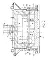
- the transport system is particularly suitable for roller hearth furnaces with central heating of the cylindrical hollow bodies, in which the burners - as shown in FIG. 2 - are arranged laterally so that the fuel is blasted into the interior of the hollow bodies.
- FIGS. 9, 10 and 11 show a row of support disks with segment support disks in which a sector-shaped segment has been cut out, so that a V-shaped one Supporting edge 32, 32 b is formed.
- the V-tip of the supporting edge is arranged at a distance from the outer surface 20 a, so that in the event that sleeve pipes have to be carried, the sleeves remain at a distance from the outer surface.
- the angle between the supporting edge legs of the supporting edges 32, 32 b, which are preferably of equal length, is preferably approximately 150 °, but, like the length of the supporting edge legs, is dependent on the diameter of the support disc, the diameter of the cylindrical hollow body to be burned and the angle of rotation with which the hollow bodies follow to be turned right or left.
- FIG. 11 shows a suitable concave-arch-shaped supporting edge which ensures a particularly soft or jerk-free transfer of the hollow body.
- a special embodiment of the invention provides that the supporting edges 32 to the supporting edges 32 b are arranged offset by 90 ° to one another, as can be seen from FIG. 1.
- support beams 34 extending shortly above the lateral surfaces 20 a and parallel to the rows of supporting disks can be provided, onto which the Hollow body 24 are deposited when they come in the region of a supporting edge 32, 32 b.
- the hollow bodies are lifted from a supporting edge 32 or 32 b and passed on to the next support disk 23 b or 23.
- a hollow body is thus rotatably carried with gusset between this support disc and the following support disc.
- a supporting beam 34 a according to FIG. 13 can also be used, which is arranged horizontally, but has a sawtooth-like stepped supporting edge with the same steps arranged one after the other, each with a vertical step edge 34 b and one in the direction of transport 27 from the step 34 b to the next stage 34 b sloping slope 34 c.
- the support disc support edges 32, 32 b, 32 f lift the hollow body over a step 34 b and place them on a slope 34 c, on which they roll a piece to the next support disc.
- glazed socket pipes 24 are fired on the outside
- the zones of the tubular shafts 24a are left glaze-free as rolling ring surfaces 9c, which come into contact with the components of the roller conveyor of the roller hearth furnace. It is known that the glaze-free rolling ring surfaces 9 c do not impair the quality of the fired sewer stoneware socket pipe 24.
- sewer stoneware socket pipes when burning sewage stoneware socket pipes, means are provided for preventing the socket pipe from drifting when the pipe is rotated and during transport.
- sewer stoneware socket pipes are used with a so-called setting ring 21 c arranged on the socket 25, the z. B. is made according to the teaching of DE-AS 26 05 196.
- the stacking ring surface 21 a is preferably also unglazed.
- support rings 19 a are preferably arranged freely rotating on the support rollers 10 to the side of the setting ring 21 c.
- the support rings 19 a are in rolling contact with the respective set ring 21 c, so that lateral drift is prevented.
- FIGS. 15 and 16 Other guide means according to the invention against lateral drifting of the sewer stoneware socket pipes 24 can be seen in FIGS. 15 and 16.
- a glaze-free rolling surface 9 c designed as a concave groove 22 a is introduced close behind the sleeve 25 in the transition to the tubular shaft 24 a of the sewer stoneware sleeve pipe 24, into which a correspondingly spherical support ring 10 a engages.
- the other support rings 10 a are preferably also spherical, so that there is only a narrow contact zone with the rolling surfaces 9 c, which can accordingly be made correspondingly narrow (not shown).
- the support disks 23, 23b, 23f expediently serve simultaneously as support rings and are correspondingly spherical. They engage in correspondingly concave grooves.
- the longitudinal axis 24 b of the sewer stoneware socket pipe 24 is mounted at a slightly downward incline towards the end opposite the socket, e.g. B. by 1 to 2 °, so that the sewer stoneware sleeve pipe 24 tends to hit with the sleeve against the engaging in the groove 22 a support ring 10 a, so that the drifting in the direction of arrow 24 c provokes, but is limited.
- the oblique position, not shown, of the sewer stoneware socket pipe 24 can be ensured by a correspondingly crooked axis of the support rollers 10 or by a corresponding reduction in diameter of the support ring 10a which engages in the groove 22a laterally at a distance from one another, with the diameter of the support ring to support ring can be continuously reduced (not shown). Likewise, the diameters of the laterally adjacent support disks can be reduced accordingly if the support disks are simultaneously used as support rings.
- FIG. 16 shows another guide means against lateral drift.
- a disk 26 and a support ring 27 b On an axis 25 a sit a disk 26 and a support ring 27 b at a lateral distance.
- the support ring 27 b rolls on the preferably unglazed lateral surface 9 c of the sewer stoneware socket pipe 24, which is arranged immediately behind the socket edge 29 a, while the side surface of the disk 26 a abuts against the front edge 28 a of the socket 25 or a stacking ring (not shown) .
- the disc 26 a and / or the support ring 27 b can rotate freely or firmly on the axis 25 a. In the latter case, the axis 26 a is driven or is freely rotatable.
- the disk 26 a and the support ring 27 b can be rotated freely on the axles 25 a and 25 b, the axles not being driven.
- the support disks 23 and 23b can serve as support rings.
Abstract
Description
Die Erfindung betrifft ein Verfahren und eine Vorrichtung zum Brennen von Rohren, insbesondere von keramischen Rohren, vorzugsweise von Muffen aufweisenden, innen und außen glasierten Kanalisationssteinzeugrohren im Schnellbrandverfahren. Steinzeugrohre mit Muffe, die z. B. für die Erstellung einer Kanalisation verwendet werden, werden in der Regel aufrechtstehend auf Tunnelofenwagen durch einen Tunnelofen gefahren und dabei gebrannt. Die Verweilzeit eines Steinzeugrohres im Ofen ist sehr lang; sie beträgt in der Regel 30 bis 50 Stunden. Steinzeugrohre bestehen aus keramischem Material, das durch Trocknen und Brennen einer Masse aus keramischen Rohmaterialien verfestigt worden ist. Die keramische Masse schwindet beim Trocknen und Brennen. Die Verfestigung erfolgt über einen Sinterprozeß, bei dem das Material in einen plastischen Zustand gerät. Das Trocknen und Brennen muß daher sehr sorgfältig geregelt durchgeführt werden. Steinzeugrohre sind außerdem außen- und vorzugsweise auch innenseitig glasiert. Das Glasurmaterial bildet während des Brennens eine zähklebrige Schmelze, die nach dem Erkalten einen dichten festen Glasphasenüberzug ergeben soll. Die Steinzeugrohre dürfen während der Schmelzphasenbildung nicht in Kontakt miteinander oder mit anderen Gegenständen kommen, weil andernfalls eine Verklebung oder eine Störung der Glasur bewirkt werden könnte, so daß das Steinzeugrohr unbrauchbar würde. Das bekannte Verfahren erfordert hohe Energiekosten, weil insbesondere auch die Tunnelofenwagen Wärme absorbieren, die verloren geht. Außerdem sind zahlreiche Arbeitsvorgänge erforderlich.The invention relates to a method and a device for firing pipes, in particular ceramic pipes, preferably of sewer stoneware pipes with sleeves, glazed inside and outside, using the rapid firing method. Stoneware pipes with a sleeve, the z. B. used for the construction of a sewer system, are usually driven upright on tunnel kiln cars through a tunnel kiln and burned. A stoneware pipe stays in the furnace for a very long time; it is usually 30 to 50 hours. Stoneware pipes are made of ceramic material that has been solidified by drying and firing a mass of ceramic raw materials. The ceramic mass shrinks as it dries and burns. The solidification takes place via a sintering process in which the material gets into a plastic state. The drying and burning must therefore be carried out very carefully. Stoneware pipes are also glazed on the outside and preferably also on the inside. The glaze material forms a viscous melt during firing, which should result in a tight, solid glass phase coating after cooling. The stoneware pipes must not come into contact with one another or with other objects during the melting phase formation, because otherwise the glueing or the glaze could be disturbed, so that the stoneware pipe would become unusable. The known method requires high energy costs, because the tunnel kiln cars in particular absorb heat that is lost. In addition, numerous operations are required.
Die Steinzeugrohre schwinden erheblich bei der Einwirkung von Wärmeenergie bzw. bei den durch die Wärmeenergie bewirkten physikalisch-chemischen Brennreaktionen. Dabei entstehen im Bereich zwischen der Oberfläche des nicht mitschwindenden Tunnelofenwagens und dem schwindenden Steinzeugrohr u.a. auch durch das hohe Gewicht des Steinzeugrohres und durch die rauhe Oberfläche des Tunnelofenwagens Reibkräfte, die zu Deformationen des Steinzeugrohres, insbesondere im Spitzenbereich, führen können. Die Rohrenden können z. B. unrund werden oder sogar reißen, woraus ein unbrauchbares, fehlerhaftes Steinzeugrohr resultieren kann. Außerdem kann die zulässige Shaftdurchbiegung überschritten werden.The stoneware pipes shrink considerably under the influence of thermal energy or in the physico-chemical burning reactions caused by the thermal energy. This creates in the area between the surface of the tunnel kiln car that does not vanish and the fading stoneware pipe, among other things. also due to the heavy weight of the stoneware pipe and the rough surface of the tunnel kiln car friction forces that can lead to deformation of the stoneware pipe, especially in the tip area. The pipe ends can e.g. B. become out of round or even tear, which can result in an unusable, faulty stoneware pipe. In addition, the permissible shaft deflection can be exceeded.
Hinzu kommt, daß die Wärmeenergieverteilung im Tunnelofen inhomogen sein kann. Dies ergibt sich insbesondere dadurch, daß die Steinzeugrohre auf einem Tunnelofenwagen so dicht wie möglich gesetzt stehen, daß die Brenngase nicht jedes Rohr gleichmäßig mit Wärmeenergie beaufschlagen können, woraus sogenannter Schwachbrand oder überbranntes, deformiertes Material resultieren können, die zu Ausschußware führen können. Insbesondere ist die Übergangszone zwischen dem Rohr und der Muffe, über die die Last des Rohres in die Muffe geleitet wird, kritisch. Wird diese Zone nicht optimal mit Wärmeenergie versorgt, können Spannungen während des Brennens in diesem Bereich auftreten, die zu Rissen führen und das Rohr unbrauchbar machen.In addition, the heat energy distribution in the tunnel kiln can be inhomogeneous. This results in particular from the fact that the stoneware pipes are placed as close as possible on a tunnel kiln car that the fuel gases cannot apply heat energy evenly to each pipe, which can result in so-called weak fire or overburned, deformed material, which can lead to rejects. In particular, the transition zone between the pipe and the sleeve, via which the load of the pipe is conducted into the sleeve, is critical. If this zone is not optimally supplied with thermal energy, tensions can occur in this area during firing, which lead to cracks and render the pipe unusable.
Es hat nicht an Versuchen gefehlt, das oben beschriebene Verfahren durch ein anderes Verfahren zu ersetzen. Bisher ist jedoch kein anderes technisch durchführbares Verfahren bekannt geworden, mit dem außen glasierte Kanalisationssteinzeugmuffenrohre einwandfrei im Schnellbrandverfahren gebrannt werden können.There has been no lack of attempts to replace the method described above with another method. So far, however, no other technically feasible method is known with which glazed sewer stoneware socket pipes on the outside can be burned perfectly using the rapid firing method.
Es sind Verfahren beschrieben worden, wonach Rohre ohne Muffen und ohne Glasur liegend und ggf. auch sich um ihre Längsachse drehend transportiert, getrocknet und/oder verfestigt werden können. Diese Verfahren eignen sich aber nicht zum Trocknen oder gar Brennen von glasierten, Muffen aufweisenden Kanalisationssteinzeugrohren aus keramischem Material, weil zum einen keramisches Material besonderer Vorkehrungen hinsichtlich Schwindung und Viskosität bedarf und weil zum anderen die Glasurschmelze eine Kontaktierung mit Gegenständen beim Brennen ausschließt.Methods have been described according to which pipes can be transported, dried and / or solidified without sleeves and without glaze and possibly also rotating about their longitudinal axis. However, these processes are not suitable for drying or even firing glazed sewer stoneware pipes made of ceramic material, because on the one hand ceramic material requires special precautions with regard to shrinkage and viscosity and on the other hand because the glaze melt prevents contact with objects during firing.
Z.B. wird in der DE-OS 29 21 200 ein Verfahren zur Herstellung zylindrischer, keramischer Rohre beschrieben, mit dem eine bessere Wirtschaftlichkeit gewährleistet werden soll und außerdem gewährleistet werden soll, daß die Rundheit der Rohre erhalten bleibt. Die Rohre werden liegend durch die Vorwärmzone und liegend und abrollend durch die Brennzone und liegend durch die Abkühlzone transportiert. Als Transportmittel dienen mit Endlosketten in Verbindung stehende stabförmige Schieber und Träger, die die Rohre berühren müssen. Dies ist jedoch bei glasierten Rohren nicht durchführbar, weil die Glasur, insbesondere wenn sich - wie in der Hauptbrennzone beabsichtigt - die Rohre drehen, beschädigt wird. In der Hauptbrennzone rollen die Rohre zudem auf einer Rampenfläche ab, so daß eine schmelzflüssige, klebrige Glasur teilweise von der Rampenfläche abgetragen würde. Die Rampe soll dafür sorgen, daß die Rohre beim Brennen in viskosem Zustand nicht durchsacken. Wenn die Rohre Muffen aufweisen, sollen diese über die Rollfläche seitlich hinaushängen.For example, DE-OS 29 21 200 describes a process for the production of cylindrical, ceramic pipes with which better economy is to be ensured and also to ensure that the roundness of the pipes is preserved. The pipes are transported lying through the preheating zone and lying and rolling through the burning zone and lying through the cooling zone. Rod-shaped sliders and supports, which must touch the pipes, are used as transport means with endless chains. However, this is not feasible for glazed pipes because the glaze is damaged, especially if the pipes rotate, as intended in the main combustion zone. In the main burning zone, the pipes also roll on a ramp surface, so that a molten, sticky glaze would be partially removed from the ramp surface. The ramp is designed to ensure that the pipes do not sag when fired in a viscous state. If the pipes have sleeves, they should hang laterally over the rolling surface.
Die Rotation der Rohre ist, abhängig von der Transportgeschwindigkeit, sehr langsam, so daß die an den Brennern vorbeiziehenden Rohrenden punktförmig überhitzt werden.The rotation of the pipes is very slow, depending on the transport speed, so that the pipe ends passing the burners are overheated in a punctiform manner.
In der Brennzone sollen die Transportketten durch die Wandung der Rampe gegen unzulässige Wärmeeinwirkung geschützt sein, indem die Schieber lediglich einen Schlitz in der Rampenwandung durchgreifen. Die Schlitze lassen jedoch noch zuviel Wärme durch, so daß die Funktion der Transportkette gefährdet ist. Aufgrund der Kettenlängung durch Wärmedehnung und Gelenkverschleiß wird der Taktweg von Brenner zu Brenner ungenau. Dieses seit langem bekannte Verfahren hat wegen der genannten Nachteile bislang keine Verwirklichung zur Herstellung von Muffen aufweisenden, beidseits glasierten Kanalisationssteinzeugrohren erfahren.In the firing zone, the wall of the ramp should protect the transport chains against inadmissible heat by simply pushing the slides through a slot in the wall of the ramp. However, the slots allow too much heat to pass through, so that the function of the transport chain is jeopardized. Due to chain elongation due to thermal expansion and joint wear, the cycle path from burner to burner becomes imprecise. This method, which has been known for a long time, has so far not been implemented because of the disadvantages mentioned, for the manufacture of sewer stoneware pipes with sleeves on both sides.
Dem aus der DE-PS 1 268 318 bekannten Verfahren sowie der daraus bekannten Vorrichtung zum Brennen keramischer Gegenstände kreisförmigen Querschnitts haften nahezu die gleichen, oben anhand der DE-OS 29 21 200 beschriebenen Nachteile an. Das gleiche gilt für den Gegenstand der US-PS 2 612 706, der sich mit der Trocknung von Tonrohren befaßt. Die Tonrohre werden bei diesem bekannten Verfahren auf Rollen liegend durch den Trockenofen befördert. Die Rollen werden mit einer Kette in Längsrichtung des Ofens transportiert, wobei sie gleichzeitig um ihre Längsachse drehbar ausgebildet und auf einer auf dem Ofenfundament angeordneten Schiene abrollen, so daß sie sich um ihre Längsachse drehen und bewirken, daß die von ihnen getragenen Tonrohre ebenfalls gedreht werden. Diese Drehung der Tonrohre ermöglicht kürzere Trocknungszeiten.The method known from DE-PS 1 268 318 and the device for firing ceramic objects of circular cross section known therefrom have almost the same disadvantages described above with reference to DE-OS 29 21 200. The same applies to the subject of US Pat. No. 2,612,706, which deals with the drying of clay pipes. In this known method, the clay pipes are transported lying on rollers through the drying oven. The rollers are transported with a chain in the longitudinal direction of the furnace, being simultaneously rotatable about their longitudinal axis and rolling on a rail arranged on the furnace foundation, so that they rotate about their longitudinal axis and cause the clay pipes they carry to also be rotated . This rotation of the clay pipes enables shorter drying times.
Im europäischen Patent 0 131 955 wird ein Verfahren zum Brennen keramischer Rohre in einem Rollenherdofen beschrieben, bei dem die Rohre auf Kreisscheiben von Stützrollen liegend durch den Ofen transportiert werden. Die Stützrollen werden dabei mit einer Umfangsgeschwindigkeit gedreht, die unabhängig von der Transportgeschwindigkeit geregelt werden kann, so daß die auf den Kreisscheiben liegenden Rohre gedreht werden, und zwar mit vorwählbarer Geschwindigkeit. In der Sinterzone wird der Transport unterbrochen, die Eigendrehung der Rohre jedoch aufrechterhalten.European patent 0 131 955 describes a method for firing ceramic tubes in a roller hearth furnace, in which the tubes are transported through the furnace lying on circular disks of support rollers. The support rollers are included rotated a peripheral speed that can be controlled independently of the transport speed, so that the tubes lying on the circular disks are rotated, namely at a preselectable speed. Transport is interrupted in the sintering zone, but the pipes' own rotation is maintained.
Insbesondere nachteilig bei den beschriebenen bekannten Rollenherdöfen ist, daß die Trag- und Stützeinrichtung durch die Brennzone transportiert wird, sich dabei aufheizt und beim Verlassen der Brennzone wieder abgekühlt wird. Das bedeutet, daß sie erheblichen Temperaturwechseln ausgesetzt ist und materialmäßig sowie konstruktiv dementsprechend ausgebildet sein muß.A particular disadvantage of the known roller hearth furnaces described is that the carrying and supporting device is transported through the firing zone, heats up in the process and is cooled again when it leaves the firing zone. This means that it is exposed to considerable changes in temperature and must be designed accordingly in terms of material and construction.
Neben den Rollenherdöfen, deren Trag- und Stützeinrichtungen transportiert werden, sind auch Brennöfen mit feststehender stationärer Rollenbahn, jedoch sich drehenden Rollen, bekannt (DE-OS 29 47 540, DE-OS 33 01 660). Die Drehung der Rollen bewirkt den Transport des zu brennenden keramischen Gutes, z. B. von Wandplatten oder Fliesen. Um ein Anbacken von z. B. Glasurbestandteilen der zu brennenden Gegenstände an den Rollen zu vermeiden, sollen die als Rohre ausgebildeten Rollen Erhebungen und Vertiefungen aufweisen, so daß sich im Querschnitt sternförmige Rohre ergeben. Die zu brennenden Gegenstände liegen dann nur auf den Erhöhungen auf, wodurch die Berührungsfläche zwischen der Unterseite des zu brennenden Gegenstandes und den Rollen stark verringert ist.In addition to the roller hearth furnaces, the carrying and supporting devices of which are transported, kilns with a fixed stationary roller conveyor but rotating rollers are also known (DE-OS 29 47 540, DE-OS 33 01 660). The rotation of the rollers causes the transport of the ceramic material to be fired, e.g. B. of wall panels or tiles. To bake z. B. to avoid glaze components of the objects to be burned on the rollers, the rollers designed as tubes should have elevations and depressions, so that there are star-shaped tubes in cross section. The objects to be burned then lie only on the elevations, as a result of which the contact area between the underside of the object to be burned and the rollers is greatly reduced.
Mit diesen feststehende Rollenbahnen aufweisenden Öfen können keine Rohre, insbesondere keine keramischen Muffenrohre, gebrannt werden, weil sich Rohre mit den stationären Rollen nicht transportieren lassen.With these furnaces having fixed roller conveyors, no pipes, in particular no ceramic socket pipes, can be burned because pipes with the stationary rolls do not allow to be transported.
Aus der DE-OS 25 20 462, insbesondere Fig. 16, ist ein Wärmeschrank mit einer Transportvorrichtung bekannt, mit der Rohre unter Eigendrehung mit rohrförmigen Stangen durch den Wärmeschrank transportiert werden. Die in Schlitzen geführten Enden der Stangen liegen auf Kurbelzapfen von senkrecht zur Längserstreckung der Stangen angeordneten,angetriebenen, sich drehenden Kurbelwellen auf. Die Winkelversetzung der Kurbelzapfen ist so gewählt, daß die Stangen eine Auflageeinrichtung mit sinusförmigem Gang bilden. Aufgrund der ständigen Drehung der Kurbelwellen verändert sich die von den Stangen gebildete Auflageeinrichtung mit sinusförmigem Gang fortschreitend unter Aufrechterhaltung des gleichen Taktes und der gleichen Amplitude. Daraus resultiert eine überlagerte Translations-Rotationsbewegung der Rohre.From DE-OS 25 20 462, in particular Fig. 16, a heating cabinet with a transport device is known, with which pipes are transported through the heating cabinet with tubular rods under their own rotation. The ends of the rods, which are guided in slots, rest on crank pins of driven, rotating crankshafts arranged perpendicular to the longitudinal extension of the rods. The angular displacement of the crank pin is chosen so that the rods form a support device with a sinusoidal path. Due to the constant rotation of the crankshafts, the support device formed by the rods with sinusoidal gear changes progressively while maintaining the same cycle and the same amplitude. This results in a superimposed translational rotational movement of the tubes.
Das Brennen von keramischen Rohren mit dieser bekannten Vorrichtung wäre wegen der hohen Anwendungstemperaturen ungünstig. Außerdem ist die bekannte Vorrichtung kompliziert aufgebaut; denn die Hubbewegung der Stangen erfordert einen erheblichen konstruktiven Aufwand, insbesondere wegen der Abdichtungsprobleme in den Ofenseitenwänden.The firing of ceramic tubes with this known device would be unfavorable because of the high application temperatures. In addition, the known device is of complex construction; because the lifting movement of the rods requires considerable design effort, especially because of the sealing problems in the side walls of the furnace.
Aufgabe der Erfindung ist, ein Verfahren und eine Vorrichtung aufzuzeigen, bei denen mit einfachen stationären Mitteln ein schonender Transport von zu brennenden Rohren unter Eigendrehung und beim Brennen ohne Weitertransport unter Eigendrehung möglich ist. Bei vorzugsweise taktendem Transport soll der Transportweg genau definiert sein. Diese Aufgabe wird durch die Merkmale der Ansprüche 1 und 7 gelöst. Vorteilhafte Weiterbildungen der Erfindung werden in den von diesen Ansprüchen abhängigen Unteransprüchen gekennzeichnet. Anhand der Zeichnung wird die Erfindung im folgenden beispielhaft näher erläutert. Es zeigen:
- Fig. 1 einen vertikalen Längsschnitt durch einen erfindungsgemäßen Rollenherdofen,
- Fig. 2 einen Querschnitt durch den Ofen nach Fig. 1,
- Fig. 3 einen horizontalen Längsschnitt durch den Ofen nach Fig. 1,
- Fig. 4 eine Frontansicht einer Rolle der Rollenbahn mit schematisch angedeutetem Ofen,
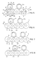
- Fig. 5 eine schematische Seitenansicht der Rollenbahn mit einer Ausführungsform der Stützscheiben in Drehantriebsstellung,
- Fig. 6 eine schematische Seitenansicht der Rollenbahn in Transportübergabestellung,
- Fig. 7 eine schematische Seitenansicht der Rollenbahn in Transportübernahmestellung,
- Fig. 8 eine schematische Seitenansicht der Rollenbahn in Drehantriebsstellung nach der Übernahme der Rohre,
- Fig. 9 eine schematische Seitenansicht der Rollenbahn mit einer anderen Ausführungsform der Stützscheiben,
- Fig. 10 eine Seitenansicht einer Stützscheibe der Rollenbahn gemäß Fig. 9,
- Fig. 11 eine Seitenansicht einer dritten Ausführungsform einer Stützscheibe einer Rollenbahn,
- Fig. 12 schematisch eine Seitenansicht einer weiteren Ausführungsform einer Rollenbahn mit Abrollbalken,
- Fig. 13 schematisch eine Seitenansicht eines anderen Abrollbalkens einer Rollenbahn,
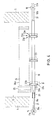
- Fig. 14 schematisch einen Teil eines Querschnitts durch den Ofen mit einer Führungseinrichtung für die Rohre,
- Fig. 15 schematisch eine andere Führungseinrichtung,
- Fig. 16 schematisch eine weitere Führungseinrichtung.
- 1 is a vertical longitudinal section through a roller hearth furnace according to the invention,
- 2 shows a cross section through the furnace according to FIG. 1,
- 3 shows a horizontal longitudinal section through the furnace according to FIG. 1,
- 4 is a front view of a roller of the roller conveyor with a schematically indicated furnace,
- 5 is a schematic side view of the roller conveyor with an embodiment of the support disks in the rotary drive position,
- 6 is a schematic side view of the roller conveyor in the transport transfer position,
- 7 is a schematic side view of the roller conveyor in the transport takeover position,
- 8 is a schematic side view of the roller conveyor in the rotary drive position after taking over the tubes,
- 9 is a schematic side view of the roller conveyor with another embodiment of the support disks,
- 10 is a side view of a support disc of the roller conveyor according to FIG. 9,
- 11 is a side view of a third embodiment of a support disc of a roller conveyor,
- 12 schematically shows a side view of a further embodiment of a roller conveyor with rolling bars,
- 13 schematically shows a side view of another rolling bar of a roller conveyor,
- 14 schematically shows a part of a cross section through the furnace with a guide device for the pipes,
- 15 schematically shows another guide device,
- 16 schematically shows a further guide device.
Der Rollenofen 1 ist mit einer Rollenbahn 9 ausgerüstet, die mehrere in Längsrichtung des Ofens auf gleichen Abstand voneinander angeordnete, in einer Ebene, vorzugsweise in einer horizontalen Ebene, liegende, stationär gelagerte Rollen 10 aufweist. Die Rollenbahn 9 befindet sich im Abstand über dem Ofenboden 3 und teilt den Ofeninnenraum 11 in einen oberen Brennraum 12 und einen unteren Ofenraum 13; sie erstreckt sich in Längsrichtung des Ofens somit von der Rückwand 6 zur Frontwand 7.The roller furnace 1 is equipped with a
Durch die Seitenwände 4, 5 ragen sich gegenüberliegend oder versetzt horizontal angeordnete, zur vertikalen Längsmittenebene 15 gerichtete, in Längsrichtung des Ofens auf Abstand aneinandergereihte Brenner 14, die in geringem Abstand über der Rollenbahn, vorzugsweise im Mittelpunkt der keramischen Rohre, positioniert sind.Through the
Die Rollen 10 durchgreifen entsprechende Löcher in den Seitenwänden 4, 5, wobei ihre Rollenstümpfe 10 a, 10 b aus dem Ofen 1 ragen und Kupplungselemente 16 für ein Antriebsmittel 17 a, 17 b tragen. Geeignet ist jedes Antriebsmittel, das nach der Erfindung die Rollen 10 gleichzeitig, gleichmäßig und gleichsinnig, d.h. mit gleicher Drehrichtung, um ihre Längsachse 10 c antreibt, wobei eines der Antriebsmittel 17 a (oder 17 b) eine bestimmte Drehrichtung 18 (oder 19) und das andere Antriebsmittel 17 b (oder 17 a) die entgegengesetzte Drehrichtung 19 (oder 18) erzeugt.The
Die Rolle 10 ist z.B. aus einem Rollenrohr 20 aufgebaut, in dessen Endbereiche Wellenstümpfe 21 eingesetzt sind (Fig. 4). Wesentlich ist, daß die Rollenrohre im im Ofeninnenraum 11 liegenden Abschnitt mit Stützscheiben 23 als Tragelemente für die zu brennenden Gegenstände besetzt sind, die drehfest auf dem jeweiligen Rollenrohr 20 lagern. Dabei sind mehrere Stützscheiben 23 auf einem Rollenrohr 20 im Abstand - vorzugsweise im gleichen Abstand - voneinander angeordnet. Jede Rolle 10 des Rollenofens gemäß den Fig. 1 bis 3 tragen z. B. vier Stützscheiben 23; die Rolle 10 der Rollenbahn gemäß Fig. 4 trägt lediglich drei Stützscheiben 23. Die Anzahl der Stützscheiben richtet sich nach dem zu tragenden Gewicht. Als zu tragende und zu brennende Gegenstände sind Muffen 25 aufweisende Steinzeugrohre 24 dargestellt, für die der erfindungsgemäße Rollenofen insbesondere eingesetzt werden kann. Der erfindungsgemäße Rollenofen ist für Steinzeugrohre 24 unterschiedlichen Durchmessers verwendbar, wie Fig. 3 zeigt. Bei Steinzeugrohren 24 großen Durchmessers werden die Rohre vorzugsweise in Folge wechselnd, d.h. das eine Steinzeugrohr mit der Muffe 25 zur Seitenwand 4 und das folgende mit der Muffe 25 zur Seitenwand 5 weisend auf den Stützscheiben 23 gelagert. Der Durchmesser der Stützscheibe ist erfindungsgemäß so groß gewählt, daß zwischen der Muffe 25 eines Steinzeugrohres 24 und der Mantelfläche eines Rollenrohres 20 ein Abstand verbleibt und die Muffe seitlich zwischen der jeweiligen Seitenwand 4 oder 5 und der jeweils außenseitigen letzten Stützscheibe 23 angeordnet ist (siehe Fig. 4).The
Erfindungsgemäß ist der Abstand benachbarter Rollenrohre 20 voneinander in der Rollenbahn 9 und der Durchmesser der Stützscheiben 23 so gewählt, daß die Umfangsringfläche 23 a einer Stützscheibe nur in geringem Abstand von der Mantelfläche 20 a der beiden benachbarten Rollenrohre 20 angeordnet ist, so daß sich die Flächen 20 a und 23 a nicht berühren. Im Zusammenhang damit sind die Stützscheiben 23 b eines zu einem bestimmten Rollenrohr 20 benachbarten Rollenrohres 20 b seitlich derart versetzt zu den Stützscheiben 23 des einen bestimmten Rollenrohres 20 angeordnet, daß sich die Stützscheiben 23 und 23 b seitlich überlappen. Der Radius R der Stützscheibe 23, 23 b ist demgemäß größer, als die Hälfte des Abstandes A zwischen zwei benachbarten Rollenrohren 20 beträgt (Fig. 5), so daß sich ein Überlappungsbereich 26 ergibt. Die seitliche Versetzung ist so gering wie möglich gewählt, damit die sich aus der Versetzung ergebende Tragbreite B einer Stützscheibenreihe 23 c so klein wie möglich bleibt (Fig. 4). Eine Stützscheibenreihe 23 c ergibt sich somit aus der Stützscheibenreihe 23 d, die aus den in Längsrichtung bzw. Transportrichtung 27 (Fig. 3) hintereinander angeordneten Stützscheiben 23 gebildet wird, die jeweils auf jedem übernächsten Rollenrohr 20 sitzen,und der Stützscheibenreihe 23 e, die aus den in Transportrichtung 27 hintereinander angeordneten Stützscheiben 23 b gebildet wird und die auf den zwischen den Rollenrohren 20 angeordneten, jeweils übernächsten Rollenrohren 20 b sitzen.According to the distance between
In den keilförmigen Zwickeln 28 zwischen zwei zusammenwirkenden Stützscheiben 23 und 23 b (Fig. 5) lagern die Rohrschäfte 24 a der Rohre 24. Durch die gleichsinnige Drehung der Stützscheiben 23, 23 b z. B. in Richtung 19 werden die Rohre 24 mit entgegengesetzter Drehrichtung 29 gedreht (Fig. 6). Da die Stützscheiben 23, 23 b auch in die Drehrichtung 18 antreibbar sind, können die Rohre 24 auch in die zur Drehrichtung 29 entgegengesetzte Drehrichtung 30 gedreht werden (Fig. 5).In the wedge-shaped
Erfindungsgemäß werden die quer zur Transportrichtung 27 liegenden, zu brennenden Gegenstände mit den stationär angeordneten Stützscheiben 23, 23 b in oder gegen die Transportrichtung 27 translatorisch transportiert. Zu diesem Zweck sind die Stützscheiben als Segmentstützscheiben ausgebildet und weisen z. B. Sehnensegmentabschnitte 31 auf, woraus gerade Sehnentragkanten 32, 32 b resultieren, wobei die Sehnentragkante 32 zur Stützscheibe 23 und die Sehnentragkante 32 b zur Stützscheibe 23 b gehören. Die Sehnentragkanten befinden sich im Abstand über der Mantelfläche 20 a des Rollenrohres 20, und zwar so weit, daß die Muffen 25 der Muffenrohre 24 nicht in Kontakt mit der Mantelfläche 20 a bzw. mit der Tragrolle 10 der Tragrollenbahn 9 kommen, wenn der Rohrschaft 24 a auf den zusammenwirkenden Sehnentragkanten 32, 32 b aufliegt.According to the invention, the objects which are to be burned and lie transversely to the
Die gleichlangen Sehnentragkanten 32, 32 b aller Stützscheiben weisen vorzugsweise die gleiche Ausrichtung an den gleichen Stellen der Stützscheiben 23, 23 b auf, so daß sie in einer den Muffenrohren 24 abgewandten Stellung und in einer die Muffenrohre 24 tragenden, um 180° gedrehten Stellung miteinander in einer Ebene fluchtend und in den anderen davon abweichenden Stellungen parallel versetzt zueinander angeordnet sind. Die Länge einer Sehnentragkante 32, 32 b ist so gewählt, daß die Länge der verbleibenden Umfangsscheibenkante 33 der Stützscheiben 23, 23 b ausreicht, das Muffenrohr 24 um mindestens 180° in Drehrichtung 29 oder 30 zu drehen, bevor es mit einer der Sehnentragkanten 32 oder 32 b in Kontakt kommt.The same-length
Vorzugsweise wirken jeweils zwei Stützscheiben 23, 23 b paarweise zusammen und tragen ein Muffenrohr 24. Ein anderes Muffenrohr wird von zwei anderen Stützscheiben getragen, so daß ein Zwickel 28 freibleibt. Diese Verteilung der Muffenrohre erfolgt jedoch nur, wenn der Abstand zwischen zwei Muffenrohren geringer als ihr Durchmesser bzw. der Durchmesser ihrer Muffen ist, weil sie sich andernfalls berühren würden.Preferably, two
Durch die Abschnitte 31 bzw. die als Tragkanten fungierenden Sehnenkanten 32, 32 b wird bewirkt, daß die Muffenrohre 24 bzw. die zu brennenden Gegenstände, sobald sie mit den Sehnentragkanten in Kontakt kommen, sich drehend abgesenkt und danach sich drehend wieder angehoben werden, wobei sie translatorisch zu einer benachbarten Stützscheibe 23 f befördert werden, so daß dann die Stützscheiben 23 b, 23 f paarweise zusammenwirken, wie sich aus den Fig. 5, 6, 7 und 8 ohne weiteres ergibt. Das Muffenrohr 24, das sich in Fig. 5 im Zwickel 28 zwischen den Stützscheiben 23, 23 b befunden hatte, befindet sich in Fig. 8 im Zwickel 28 b zwischen den Stützscheiben 23 b, 23 f und hat seine Position gemäß den Fig. 6 und 7 entgegen der Transportrichtung 27 verändert, weil die Stützscheiben aus der Position nach Fig. 5 um 360° in Drehrichtung 19 in die Position gemäß Fig. 8 verdreht worden sind. Bei entsprechender Drehung der Stützscheiben in Drehrichtung 18 würde das Muffenrohr 24 in Transportrichtung 27 über die Positionsphase der Fig. 8, 7, 6 in die Positionsphase gemäß Fig. 5 wandern. Auf diese Weise gelingt es, die Muffenrohre 24 in Transportrichtung 27 vor und zurück und/oder in und aus dem Rollenofen und/oder bei einem Durchlaufofen (nicht dargestellt) in und durch den Ofen zu befördern. Dabei kann die Verweilzeit der Muffenrohre im Ofen vorbestimmt werden. Die Muffenrohre können bei Bedarf kontinuierlich schrittweise und sich in Richtung 29 oder 30 drehend durch den Ofen transportiert werden. Sie können während des schrittweisen Transports durch den Ofen, aber auch - was bevorzugt wird - schrittweise vor- und zurücktransportiert und im Stillstand einmal oder mehrmals die Drehrichtung wechselnd gedreht werden. Ferner kann dabei vorgesehen sein, die Drehung kurzzeitig zu stoppen.The
Mit der Erfindung ist es somit gelungen, ein bezüglich der Beförderung der zu brennenden Gegenstände optimales Transportsy stem zu schaffen, dessen Bewegungsabläufe weitgehend auf die Brennerfordernisse abstimmbar und das stationär im Ofen angeordnet ist, so daß die Bestandteile des Transportsystems keinen schädigenden Temperaturwechseln ausgesetzt sind. Das Transportsystem eignet sich insbesondere für Rollenherdöfen mit zentrischem Erwärmen der zylindrischen Hohlkörper, in denen die Brenner - wie Fig. 2 zeigt - seitlich so angeordnet sind, daß das Brennmittel ins Innere der Hohlkörper gestrahlt wird.With the invention it is thus possible to achieve an optimal transport system with regard to the transport of the objects to be burned Stem to create, the motion sequences largely tuned to the burner requirements and which is arranged stationary in the furnace, so that the components of the transport system are not exposed to harmful temperature changes. The transport system is particularly suitable for roller hearth furnaces with central heating of the cylindrical hollow bodies, in which the burners - as shown in FIG. 2 - are arranged laterally so that the fuel is blasted into the interior of the hollow bodies.
Bevorzugte andere Ausführungsformen der Segmentstützscheiben 23, 23 b, 23 f zeigen die Fig.9, 10 und 11. In den Fig. 9 und 10 erkennt man eine Stützscheibenreihe mit Segmentstützscheiben, bei denen ein sektorförmiges Segment ausgespart ist, so daß eine V-förmige Tragkante 32, 32 b gebildet wird. Die V-Spitze der Tragkante ist dabei im Abstand von der Mantelfläche 20 a angeordnet, so daß für den Fall, daß Muffenrohre getragen werden müssen, die Muffen im Abstand von der Mantelfläche bleiben. Der Winkel zwischen den vorzugsweise gleich langen Tragkantenschenkeln der Tragkanten 32, 32 b beträgt vorzugsweise etwa 150°, ist aber ebenso wie die Länge der Tragkantenschenkel abhängig vom Durchmesser der Stützscheibe, dem Durchmesser des zu brennenden zylindrischen Hohlkörpers und dem Drehwinkel, mit dem die Hohlkörper nach rechts oder links gedreht werden soll. In Fig. 11 ist eine zweckmäßige konkavbogenförmige Tragkante dargestellt, die eine besonders weiche bzw. ruckfreie Übergabe des Hohlkörpers gewährleistet.Preferred other embodiments of the
Eine besondere Ausführungsform der Erfindung sieht vor, daß die Tragkanten 32 zu den Tragkanten 32 b um 90° versetzt zueinander angeordnet sind, wie sich aus Fig. 1 ergibt. In Kombination damit können neben den Stützscheibenreihen 23 c in Höhe kurz über den Mantelflächen 20 a sich parallel zu den Stützscheibenreihen erstreckende Tragbalken 34 vorgesehen sein, auf die die Hohlkörper 24 abgesetzt werden, wenn sie in den Bereich einer Tragkante 32, 32 b kommen. Die Hohlkörper werden von einer Tragkante 32 oder 32 b angehoben und an die nächste Stützscheibe 23 b oder 23 weitergegeben. Ein Hohlkörper wird so mit Zwickel zwischen dieser Stützscheibe und der folgenden Stützscheibe drehend getragen.A special embodiment of the invention provides that the supporting
Besonders vorteilhaft ist, die Tragbalken 34 in Transportrichtung 27 nach unten geneigt anzuordnen, wie Fig. 12 verdeutlicht. Danach wird die Übergabe der Hohlkörper 24 in Transportrichtung 27 von einem zum anderen Stützscheibenpaar erleichtert. Zum gleichen Zweck kann aber auch ein Tragbalken 34 a gemäß Fig. 13 dienen, der zwar horizontal angeordnet ist, jedoch eine sägezahnartige gestufte Tragkante mit hintereinander gereihten gleichen Stufen aufweist mit jeweils einer vertikalen Stufenkante 34 b und einer in Richtung Transportrichtung 27 von der Stufe 34 b zur nächsten Stufe 34 b abfallenden Schräge 34 c. Die Stützscheibentragkanten 32, 32 b, 32 f heben die Hohlkörper über eine Stufe 34 b und setzen sie auf einer Schräge 34 c ab, auf der sie ein Stück zur nächsten Stützscheibe rollen.It is particularly advantageous to arrange the support beams 34 inclined downward in the
Es liegt im Rahmen der Erfindung, anstelle von ausgesparten Segmenten bzw. anstelle von Segmentstützscheiben für den translatorischen Transport der Hohlkörper Stützscheiben mit wulstartigen, den Durchmesser erweiternden Vorsprüngen (nicht dargestellt) und/oder mit exzentrisch angeordneten Stützscheiben zu bewerkstelligen. Es liegt außerdem im Rahmen der Erfindung, auf die Stützscheiben zu verzichten und die Tragrohre 20 bzw. die Tragrollen 10 im Querschnitt betrachtet wie die Stützscheiben, d.h. mit entsprechenden Ausschnitten und/oder Wülsten, zu versehen, wenn das zu brennende Produkt vollflächig aufliegen kann.It is within the scope of the invention, instead of recessed segments or instead of segment support disks for the translational transport of the hollow bodies, to produce support disks with bead-like projections (not shown) and / or with eccentrically arranged support disks. It is also within the scope of the invention to dispense with the support disks and the
Werden dagegen außen glasierte Muffenrohre 24 gebrannt, werden nach einer Ausführungsform der Erfindung die Zonen der Rohrschäfte 24 a als Abrollringflächen 9c glasurfrei belassen, die mit den Bestandteilen der Rollenbahn des Rollenherdofens in Kontakt kommen. Es ist bekannt, daß die glasurfreien Abrollringflächen 9 c die Qualität des gebrannten Kanalisationssteinzeugmuffenrohres 24 nicht beeinträchtigen.In contrast, glazed
Des weiteren werden zweckmäßigerweise beim Brennen von Kanalisationssteinzeugmuffenrohren Mittel zum Verhindern des Driftens des Muffenrohres beim Drehen des Rohres und beim Transport vorgesehen. Zweckmäßigerweise werden dazu Kanalisationssteinzeugmuffenrohre mit einem an der Muffe 25 angeordneten sogenannten Setzring 21 c verwendet, der z. B. gemäß der Lehre der DE-AS 26 05 196 hergestellt ist. Die Setzringmantelfläche 21 a ist vorzugsweise ebenfalls unglasiert.Furthermore, expediently, when burning sewage stoneware socket pipes, means are provided for preventing the socket pipe from drifting when the pipe is rotated and during transport. Appropriately, sewer stoneware socket pipes are used with a so-called setting ring 21 c arranged on the
Nach einer Ausführungsform der Erfindung (Fig. 14) sind Stützringe 19 a vorzugsweise frei drehend auf den Tragrollen 10 seitlich des Setzringes 21 c angeordnet. Die Stützringe 19 a stehen im Rollkontakt mit dem jeweiligen Setzring 21 c, so daß ein seitliches Driften verhindert wird.According to one embodiment of the invention (Fig. 14), support rings 19 a are preferably arranged freely rotating on the
Andere erfindungsgemäße Führungsmittel gegen seitliches Driften der Kanalisationssteinzeugmuffenrohre 24 sind in den Fig. 15 und 16 erkennbar.Other guide means according to the invention against lateral drifting of the sewer
Gemäß Fig. 15 ist eine als konkave Rille 22 a ausgebildete glasurfreie Abrollfläche 9 c dicht hinter der Muffe 25 im Übergang zum Rohrschaft 24 a des Kanalisationssteinzeugmuffenrohres 24 eingebracht, in die formschlüssig ein entsprechend ballig ausgeführter Stützring 10 a greift. Die anderen Stützringe 10 a sind vorzugsweise ebenfalls ballig ausgebildet, so daß nur eine schmale Berührungszone mit den Abrollflächen 9 c gegeben ist, die demgemäß entsprechend schmal ausgeführt sein kann (nicht dargestellt). Zweckmäßigerweise dienen die Stützscheiben 23, 23 b, 23 f gleichzeitig als Stützringe und sind entsprechend ballig ausgeführt. Sie greifen in entsprechend konkave Rillen.15, a glaze-
Vorzugsweise ist insbesondere bei dieser Ausführungsform der Führungsmittel die Längsachse 24 b des Kanalisationssteinzeugmuffenrohres 24 zum Muffenende entgegengesetzten Ende hin etwas nach unten geneigt gelagert, z. B. um 1 bis 2°, so daß das Kanalisationssteinzeugmuffenrohr 24 dazu neigt, mit der Muffe gegen den in die Rille 22 a eingreifenden Stützring 10 a zu stoßen, so daß das Driften in Pfeilrichtung 24 c zwar provoziert, jedoch begrenzt wird.Preferably, in particular in this embodiment of the guide means, the
Die schiefe, nicht dargestellte Lage des Kanalisationssteinzeugmuffenrohres 24 kann durch eine entsprechend schiefstehende Achse der Tragrollen 10 oder durch eine entsprechende Durchmesserreduzierung der zum in die Rille 22 a greifenden Stützring 10 a seitlich auf Abstand benachbarten weiteren Stützring 10 a gewährleistet sein, wobei der Durchmesser von Stützring zu Stützring kontinuierlich vermindert sein kann (nicht dargestellt). Ebenso können die Durchmesser der seitlich benachbarten Stützscheiben entsprechend vermindert sein, wenn die Stützscheiben gleichzeitig als Stützringe verwendet werden.The oblique position, not shown, of the sewer
Die Fig. 16 läßt ein anderes Führungsmittel gegen seitliches Driften erkennen. Auf einer Achse 25 a sitzen auf seitlichem Abstand eine Scheibe 26 und ein Stützring 27 b. Der Stützring 27 b rollt auf der vorzugsweise unglasierten Mantelfläche 9 c des Kanalisationssteinzeugmuffenrohres 24 ab, die unmittelbar hinter der Muffenkante 29 a angeordnet ist, während die Seitenfläche der Scheibe 26 a gegen die Frontkante 28 a der Muffe 25 oder eines Setzringes (nicht dargestellt) stößt. Dabei können die Scheibe 26 a und/oder der Stützring 27 b frei drehbar oder fest auf der Achse 25 a sitzen. Im letzteren Fall wird die Achse 26 a angetrieben oder ist frei drehbar.16 shows another guide means against lateral drift. On an
Vorteilhaft kann sein, die Scheibe 26 a auf einer Achse 25 a und den Stützring 27 a auf einer separaten, parallel zur Achse 25 a verlaufenden Achse 25 b anzuordnen und beide Achsen zur Vermeidung einer Reibung zwischen der Scheibe 26 a bzw. dem Stützring 27 b und dem Kanalisationssteinzeugmuffenrohr 24 mit entsprechend unterschiedlichen Geschwindigkeiten anzutreiben.It can be advantageous to arrange the
Auch in diesem Fall können aber die Scheibe 26 a und der Stützring 27 b frei drehbar auf den Achsen 25 a bzw. 25 b sitzen, wobei die Achsen nicht angetrieben sind. In allen Fällen können - wie oben bereits erwähnt - als Stützringe die Stützscheiben 23 bzw. 23 b dienen.In this case, too, the
Claims (36)
Applications Claiming Priority (2)
| Application Number | Priority Date | Filing Date | Title |
|---|---|---|---|
| DE19893915718 DE3915718C1 (en) | 1989-05-13 | 1989-05-13 | |
| DE3915718 | 1989-05-13 |
Publications (1)
| Publication Number | Publication Date |
|---|---|
| EP0400351A1 true EP0400351A1 (en) | 1990-12-05 |
Family
ID=6380640
Family Applications (1)
| Application Number | Title | Priority Date | Filing Date |
|---|---|---|---|
| EP90108440A Withdrawn EP0400351A1 (en) | 1989-05-13 | 1990-05-04 | Process and device for firing tubes, especially ceramic tubes, preferably externally glazed drainage pipes having sleeves |
Country Status (2)
| Country | Link |
|---|---|
| EP (1) | EP0400351A1 (en) |
| DE (1) | DE3915718C1 (en) |
Cited By (2)
| Publication number | Priority date | Publication date | Assignee | Title |
|---|---|---|---|---|
| DE102015111035A1 (en) * | 2015-07-08 | 2017-01-12 | Schwartz Gmbh | Pulley conveyor |
| CN110186276A (en) * | 2019-07-04 | 2019-08-30 | 烟台大学 | It is a kind of for improving the sintering furnace and method of jatharapanvartanasana ceramic component firing rate |
Families Citing this family (5)
| Publication number | Priority date | Publication date | Assignee | Title |
|---|---|---|---|---|
| DE4341648C1 (en) * | 1993-12-07 | 1995-01-05 | Klaus Strobel | Process for firing pipes and apparatus for carrying out the process |
| DE19841042A1 (en) * | 1998-09-09 | 2000-03-16 | Eisenmann Kg Maschbau | Workpiece charging device for industrial furnace using sliding carriages pushed through furnace on rails on two levels |
| DE19928457C1 (en) * | 1999-06-24 | 2001-01-04 | Riedhammer Gmbh Co Kg | Tunnel oven for sintering and burning rotationally symmetrical objects has transport unit with disc wheels aligned spaced from each other across longitudinal direction for holding and turning articles |
| ES2882595T3 (en) * | 2015-06-16 | 2021-12-02 | Becton Dickinson France | Transport system for annealing glass containers |
| DE102017215605A1 (en) * | 2017-09-05 | 2019-03-07 | Thyssenkrupp Ag | Transport device and method for its operation |
Citations (6)
| Publication number | Priority date | Publication date | Assignee | Title |
|---|---|---|---|---|
| NL297669A (en) * | 1900-01-01 | |||
| GB290365A (en) * | 1927-02-12 | 1928-05-14 | Us Cast Iron Pipe And Foundry | Improvements in or relating to transporting mechanism for pipe annealing furnaces |
| US1927634A (en) * | 1929-02-19 | 1933-09-19 | Frank A Fahrenwald | Furnace |
| US2175834A (en) * | 1938-09-30 | 1939-10-10 | Westinghouse Electric & Mfg Co | Heat treating furnace |
| US4143753A (en) * | 1970-03-03 | 1979-03-13 | Bergens Torsten E | Conveying arrangement |
| FR2600760A1 (en) * | 1986-06-25 | 1987-12-31 | Stein Heurtey | Beam furnace for heat treating tubes with upsetting |
Family Cites Families (2)
| Publication number | Priority date | Publication date | Assignee | Title |
|---|---|---|---|---|
| DE3301660C2 (en) * | 1983-01-17 | 1985-02-14 | W. Haldenwanger Technische Keramik GmbH & Co KG, 1000 Berlin | Device for supporting flat ceramic objects to be burned in a roller kiln |
| DE3464960D1 (en) * | 1983-07-19 | 1987-08-27 | Apt Anlagen Fuer Pyrotechnik | Process and continuous oven for the thermal treatment of cylindrical objects, especially tubes, preferably made of ceramic material |
-
1989
- 1989-05-13 DE DE19893915718 patent/DE3915718C1/de not_active Expired - Lifetime
-
1990
- 1990-05-04 EP EP90108440A patent/EP0400351A1/en not_active Withdrawn
Patent Citations (6)
| Publication number | Priority date | Publication date | Assignee | Title |
|---|---|---|---|---|
| NL297669A (en) * | 1900-01-01 | |||
| GB290365A (en) * | 1927-02-12 | 1928-05-14 | Us Cast Iron Pipe And Foundry | Improvements in or relating to transporting mechanism for pipe annealing furnaces |
| US1927634A (en) * | 1929-02-19 | 1933-09-19 | Frank A Fahrenwald | Furnace |
| US2175834A (en) * | 1938-09-30 | 1939-10-10 | Westinghouse Electric & Mfg Co | Heat treating furnace |
| US4143753A (en) * | 1970-03-03 | 1979-03-13 | Bergens Torsten E | Conveying arrangement |
| FR2600760A1 (en) * | 1986-06-25 | 1987-12-31 | Stein Heurtey | Beam furnace for heat treating tubes with upsetting |
Cited By (2)
| Publication number | Priority date | Publication date | Assignee | Title |
|---|---|---|---|---|
| DE102015111035A1 (en) * | 2015-07-08 | 2017-01-12 | Schwartz Gmbh | Pulley conveyor |
| CN110186276A (en) * | 2019-07-04 | 2019-08-30 | 烟台大学 | It is a kind of for improving the sintering furnace and method of jatharapanvartanasana ceramic component firing rate |
Also Published As
| Publication number | Publication date |
|---|---|
| DE3915718C1 (en) | 1990-09-20 |
Similar Documents
| Publication | Publication Date | Title |
|---|---|---|
| DE102006020781B3 (en) | oven | |
| DE2840283C2 (en) | Tunnel furnace with a roller hearth for firing ceramic or refractory materials | |
| DE2911519C2 (en) | Method and device for protecting the underside of ceramic tiles and the rollers of a roller tunnel kiln | |
| DE3915718C1 (en) | ||
| WO2013144329A1 (en) | Vessel lid for a thermal plant | |
| DE3401792C3 (en) | Device for supporting the material treated in continuously operating heat treatment furnaces | |
| EP0131955B1 (en) | Process and continuous oven for the thermal treatment of cylindrical objects, especially tubes, preferably made of ceramic material | |
| DE19725162A1 (en) | Horizontal firing especially of stoneware pipes | |
| DE2111104C3 (en) | Device and method for bending glass panes | |
| CH409756A (en) | Stone pile and method for creating the same and setting machine for carrying out the method | |
| DE2717784B2 (en) | Trolley for fittings, tiles or other ceramic products in a tunnel kiln | |
| DE1914372C3 (en) | Method and device for producing bodies from expanded clay or the like | |
| DE4411412C1 (en) | Device for loading and unloading a firing table assembly with firing material | |
| DE3410897A1 (en) | METHOD AND DEVICE FOR THE THERMAL TREATMENT OF BLOWABLE or BLOWABLE ALUMINOSILICATE-CONTAINING GOODS | |
| WO2007134713A2 (en) | Plant and process for producing cement clinker | |
| DE4102522C2 (en) | Roller conveyor in a kiln for plain tiles roof tiles | |
| DE2921200A1 (en) | METHOD FOR PRODUCING CYLINDRICAL CERAMIC OBJECTS AND BURNING STOVES AND SYSTEM FOR CARRYING OUT THIS METHOD | |
| DE19723692C2 (en) | Process for firing bricks in a roller kiln and kiln for carrying out the process | |
| EP0198961B1 (en) | Roller hearth furnace for burning a flat or plate-shaped ceramic article | |
| DE1935921A1 (en) | Roller hearth furnace with trolley moun- - ted rollers resting on rails on side of fur- | |
| EP0657709B1 (en) | Process and device for firing tubes | |
| DE3841920C1 (en) | Installation for baking glazed stoneware pipes | |
| DE968977C (en) | Rotary kiln | |
| EP1234152B1 (en) | Continuous furnace for tubular firing material | |
| DE2419552A1 (en) | TUNNEL FURNACE FOR THE THERMAL TREATMENT OF OBJECTS WITH A CIRCULAR CROSS SECTION |
Legal Events
| Date | Code | Title | Description |
|---|---|---|---|
| PUAI | Public reference made under article 153(3) epc to a published international application that has entered the european phase |
Free format text: ORIGINAL CODE: 0009012 |
|
| AK | Designated contracting states |
Kind code of ref document: A1 Designated state(s): AT BE DE GB IT NL |
|
| STAA | Information on the status of an ep patent application or granted ep patent |
Free format text: STATUS: THE APPLICATION IS DEEMED TO BE WITHDRAWN |
|
| 18D | Application deemed to be withdrawn |
Effective date: 19910606 |