EP0399402B1 - Druckregler für den Druck innerhalb der Brennstoffspeisesammelleitung einer Brennstoffspeisevorrichtung eines Verbrennungsmotors - Google Patents
Druckregler für den Druck innerhalb der Brennstoffspeisesammelleitung einer Brennstoffspeisevorrichtung eines Verbrennungsmotors Download PDFInfo
- Publication number
- EP0399402B1 EP0399402B1 EP19900109460 EP90109460A EP0399402B1 EP 0399402 B1 EP0399402 B1 EP 0399402B1 EP 19900109460 EP19900109460 EP 19900109460 EP 90109460 A EP90109460 A EP 90109460A EP 0399402 B1 EP0399402 B1 EP 0399402B1
- Authority
- EP
- European Patent Office
- Prior art keywords
- fuel
- manifold
- fuel supply
- pressure regulator
- seat
- Prior art date
- Legal status (The legal status is an assumption and is not a legal conclusion. Google has not performed a legal analysis and makes no representation as to the accuracy of the status listed.)
- Expired - Lifetime
Links
- 239000000446 fuel Substances 0.000 title claims description 33
- 230000001105 regulatory effect Effects 0.000 title claims description 5
- 238000002485 combustion reaction Methods 0.000 title claims description 4
- 230000008878 coupling Effects 0.000 claims description 4
- 238000010168 coupling process Methods 0.000 claims description 4
- 238000005859 coupling reaction Methods 0.000 claims description 4
- 238000006243 chemical reaction Methods 0.000 description 1
- 238000004891 communication Methods 0.000 description 1
- 239000012530 fluid Substances 0.000 description 1
- 238000004519 manufacturing process Methods 0.000 description 1
- 239000002184 metal Substances 0.000 description 1
- 238000000034 method Methods 0.000 description 1
- 230000000284 resting effect Effects 0.000 description 1
- 238000007789 sealing Methods 0.000 description 1
Images

Classifications
-
- F—MECHANICAL ENGINEERING; LIGHTING; HEATING; WEAPONS; BLASTING
- F02—COMBUSTION ENGINES; HOT-GAS OR COMBUSTION-PRODUCT ENGINE PLANTS
- F02M—SUPPLYING COMBUSTION ENGINES IN GENERAL WITH COMBUSTIBLE MIXTURES OR CONSTITUENTS THEREOF
- F02M69/00—Low-pressure fuel-injection apparatus ; Apparatus with both continuous and intermittent injection; Apparatus injecting different types of fuel
- F02M69/46—Details, component parts or accessories not provided for in, or of interest apart from, the apparatus covered by groups F02M69/02 - F02M69/44
- F02M69/54—Arrangement of fuel pressure regulators
Definitions
- the present invention relates to a pressure regulator for regulating the fuel pressure inside a supply manifold forming part of an internal combustion engine fule supply device, of the type indicated in the preamble of claim 1.
- Known regulators of the aforementioned type substantially comprise a cup-shaped body having a side and bottom wall, and defining a fuel chamber communicating with a fuel inlet and outlet hole.
- the outlet hole is controlled by a plunger connected to a deformable diaphragm forming a wall of the fuel chamber and which is subjected to the action of a spring designed to normally maintain the plunger against a corresponding seat and so close the outlet hole.
- the fuel inlet hole is usually formed inside or communicates with a fitting secured to the side wall of the body, or inside the bottom wall of the body.
- the outlet hole is usually formed inside or communicates with a fitting projecting from the bottom wall or the lateral surface of the body and usually forming part of a coupling in which a seat is also formed for the plunger.
- the regulator presents a fairly complex structure.
- the aim of the present invention is to provide a pressure regulator of the aforementioned type, designed to overcome the above drawbacks typically associated with known regulators.
- a pressure regulator for regulating the fuel pressure inside a fuel supply manifold forming part of an internal combustion engine fuel supply device, as defined in claim 1.
- the pressure regulator substantially comprises a cup-shaped body 1 having a side wall 2 and a bottom wall 3 defining a fuel chamber 4 communicating with a fuel inlet hole 5 and a fuel outlet hole 6.
- Said outlet hole 6 is controlled by a plunger 7 connected to a deformable diaphragm 8 forming one wall of chamber 4 and subjected to the action of a spring 9 designed to normallu maintain plunger 7 against a corresponding seat 10 and so close outlet hole 6.
- Inlet hole 5 communicates with an inlet fitting 12 projecting from bottom wall 3 and connectable in fluidtight manner inside a seat 13 on a manifold 14 forming part of the supply device.
- Outlet hole 6 communicates with an outlet fitting 15 projecting from the lateral surface 16 of body 1 and having its axis substantially perpendicular to the longitudinal axis of body 1.
- Outlet hole 6 comprises a first hole portion 6a having its axis parallel to said longitudinal axis, and a second portion 6b perpendicular to said first portion 6a and formed inside outlet fitting 15.
- Said first portion 6a houses a coupling 17, one end of which presents seat 10 for plunger 7.
- Inlet hole 5 comprises at least a first portion 5a formed inside inlet fitting 12, and a second portion 5b formed inside bottom wall 3.
- Inlet fitting 12 presents an annular groove 18 housing a seal 19 for sealing seat 13 on manifold 14, as shown clearly in Fig.1.
- Body 1 is formed, e.g. die-cast, in one piece with inlet and outlet fittings 12 and 15, or may be formed from a drawn sheet metal element, in which case, fitting 15 may be welded in a radial hole on the body, and coupling 17 secured to the inside end.
- the pressure regulator according to the present invention also comprises a cover 22, the edge of which is turned about a corresponding edge 21 of body 1, as shown clearly in Fig.1.
- cover 22 also acts a support for one end of spring 9, the other end of which conveniently rests, in known manner, on a ring 23 connected to a disc 24 in turn resting on plunger 7.
- the pressure regulator described above is designed to maintain the fuel pressure inside manifold 14 substantially constant: the fuel in manifold 14 communicates with chamber 4 on the regulator via hole 5; when the pressure inside chamber 4 exceeds a predetermined value, the force exerted on deformable diaphragm 8 overcomes the elastic reaction of spring 9, thus detaching plunger 7 from seat 10, enabling communication between chamber 4 and outlet hole 6, and draining off sufficient fuel for restoring the pressure inside chamber 4 to the required value.
- the pressure regulator described above may be fitted to a highly straightforward manifold 14 substantially comprising a single central duct with a substantially cup-shaped end housing 25.
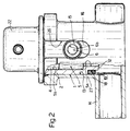
- a slot 26 in the side wall of the housing as shown clearly in Fig. 1.
- the regulator is connectable to the manifold in exactly the same way as already described.
- the regulator according to the present invention provides for accurately regulating the pressure inside manifold 14 by virtue of the rapid response afforded by the pressure inside the manifold being transmitted with practically no load loss to chamber 4 on the regulator. This is due to the design, arrangement and size of fuel inlet holes 5, which, in addition to being arranged substantially axially, may present a large diameter occupying substantially the entire section of inlet fitting 12 and most of the section of bottom wall 3 of body 1.
- the design of the regulator is extremely straightforward, by virtue of consisting of a small number of easy-to-make components.
- Body 1 in particular, may be formed in one piece using any appropriate technique enabling low-cost production.
Landscapes
- Engineering & Computer Science (AREA)
- Chemical & Material Sciences (AREA)
- Combustion & Propulsion (AREA)
- Mechanical Engineering (AREA)
- General Engineering & Computer Science (AREA)
- Fuel-Injection Apparatus (AREA)
- Control Of Fluid Pressure (AREA)
Claims (3)
- Ein Druckregler zum Regeln des Treibstoffdrucks im Inneren eines Treibstoffzufuhrverteiler (14), der einen Teil einer Kraftstoffzufuhrvorrichtung einer Verbrennungskraftmaschine bildet, wobei diese Vorrichtung einen becherförmigen Körper (1) enthält, der im wesentlichen aus einer Seitenwand (2) und einer Bodenwand (3) besteht, die eine Treibstoffkammer (4) definieren, die in Verbindung steht mit einem Treibstoffeinraßloch (5) und einem Treibstoffauslaßloch (6), welches von einem Kolben (7) gesteuert wird, der mit einer deformierbaren Membran (8) verbunden ist, die eine Wand der Kammer (4) bildet und der Kraft einer Feder (9) unterworfen ist, die so ausgelegt ist, daß sie normalerweise den Kolben (7) gegen den zugehörigen Sitz (10) drückt und so das Auslaßloch (6) schließt; wobei das Treibstoffeinlaßloch (5) in Verbindung mit einem Einlaßanschluß (12) steht, der von der Bodenwand (3) des Körpers (1) hervorsteht und in flüssigkeitsdichter Weise in einem Sitz (13) des Verteilers (14) anschließbar ist, und das Treibstoffauslaßloch (6) mit einem Auslaßanschluß (15) in Verbindung steht, welcher von der Seitenfläche (16) des Körpers (1) hervorsteht,
dadurch gekennzeichnet, daß der Einlaßanschluß (12) durch ein einstückig mit dem becherförmigen Körper (1) ausgebildetes Muffenelement gebildet ist und über die Bodenwand (3) hervorsteht, und der Auslaßanschluß (15) durch einen angeformten Vorsprung dieser Seitenwand (2) gebildet wird, der sich von der Seitenfläche (16) nach außen erstreckt und dessen Achse senkrecht auf der Längsachse des Körpers (1) steht, und daß die Seitenwand (2) einen ringförmigen Bund (21) bildet, der radial von ihrem Rand nach außen hervorsteht und von einem umgebogenen Rand eines Deckels (22) umfaßt wird, so daß der Außenrand der Membran (8) zwischen dem umgebogenen Rand und dem Bund (21) befestigt ist. - Druckregler nach Anspruch 1, gekennzeichnet durch eine Kupplung (17), die den Sitz (10) für den Kolben (7) bildet und in einen ersten Längsabschnitt (6a) des Auslaßlochs (6) eingepaßt ist.
- Druckregler nach einem der Ansprüche 1 oder 2, dadurch gekennzeichnet, daß das Muffenelement (12) eine ringförmige Nut (18) aufweist, die eine Dichtung (19) aufnimmt, um den Sitz (13) am Verteiler (14) abzudichten.
Applications Claiming Priority (2)
| Application Number | Priority Date | Filing Date | Title |
|---|---|---|---|
| IT5313089U | 1989-05-26 | ||
| IT5313089U IT217084Z2 (it) | 1989-05-26 | 1989-05-26 | Regolatore di pressione per la regolazione della pressione all internodi un collettore di alimentazione del carburante di un dispositivo dialimentazione del carburante di un motore a combustione interna |
Publications (2)
| Publication Number | Publication Date |
|---|---|
| EP0399402A1 EP0399402A1 (de) | 1990-11-28 |
| EP0399402B1 true EP0399402B1 (de) | 1993-07-28 |
Family
ID=11280193
Family Applications (1)
| Application Number | Title | Priority Date | Filing Date |
|---|---|---|---|
| EP19900109460 Expired - Lifetime EP0399402B1 (de) | 1989-05-26 | 1990-05-18 | Druckregler für den Druck innerhalb der Brennstoffspeisesammelleitung einer Brennstoffspeisevorrichtung eines Verbrennungsmotors |
Country Status (5)
| Country | Link |
|---|---|
| EP (1) | EP0399402B1 (de) |
| BR (1) | BR9002399A (de) |
| DE (1) | DE69002390T2 (de) |
| ES (1) | ES2052096T3 (de) |
| IT (1) | IT217084Z2 (de) |
Family Cites Families (5)
| Publication number | Priority date | Publication date | Assignee | Title |
|---|---|---|---|---|
| US4570600A (en) * | 1982-09-29 | 1986-02-18 | General Motors Corporation | Fuel rail assembly and method of fabrication |
| JPS60108561A (ja) * | 1983-11-15 | 1985-06-14 | Nippon Denso Co Ltd | 燃料分配管 |
| DE3505625C2 (de) * | 1985-02-19 | 1994-06-01 | Bosch Gmbh Robert | Kraftstoff-Druckregelvorrichtung |
| US4756289A (en) * | 1986-02-12 | 1988-07-12 | General Motors Corporation | Self-contained fuel pressure regulator |
| IT208360Z2 (it) * | 1986-11-18 | 1988-05-28 | Weber Srl | Gruppo per un collettore di carburante con regolatore di pressione integrato per alimentazione ad iniezione di motori a combustione interna |
-
1989
- 1989-05-26 IT IT5313089U patent/IT217084Z2/it active
-
1990
- 1990-05-18 ES ES90109460T patent/ES2052096T3/es not_active Expired - Lifetime
- 1990-05-18 EP EP19900109460 patent/EP0399402B1/de not_active Expired - Lifetime
- 1990-05-18 DE DE1990602390 patent/DE69002390T2/de not_active Expired - Fee Related
- 1990-05-22 BR BR9002399A patent/BR9002399A/pt not_active IP Right Cessation
Also Published As
| Publication number | Publication date |
|---|---|
| BR9002399A (pt) | 1991-08-06 |
| ES2052096T3 (es) | 1994-07-01 |
| IT8953130V0 (it) | 1989-05-26 |
| DE69002390T2 (de) | 1993-11-18 |
| DE69002390D1 (de) | 1993-09-02 |
| IT217084Z2 (it) | 1991-10-29 |
| EP0399402A1 (de) | 1990-11-28 |
Similar Documents
| Publication | Publication Date | Title |
|---|---|---|
| US4370102A (en) | Fluid pumping device | |
| KR100351572B1 (ko) | 연료압력진공반응식비귀환연료시스템 | |
| US6136183A (en) | Relief valve for filter device | |
| KR100295547B1 (ko) | 감압밸브 | |
| US5113898A (en) | Valve assembly for fluid pressure regulation | |
| US6247486B1 (en) | Liquid filter with built-in pressure regulator | |
| JPS61275565A (ja) | 燃料圧力調整器 | |
| US3121445A (en) | Flow control device | |
| JPS62214267A (ja) | 圧力調整装置 | |
| US6306292B1 (en) | Fuel filter with internal pressure regulator | |
| US5117860A (en) | Check valve | |
| WO1999022282A1 (en) | Flow control valves | |
| US6382183B1 (en) | Fuel system pressure regulator | |
| US5676345A (en) | Electromagnetic valve | |
| JPH0799129B2 (ja) | 調圧装置 | |
| EP0968365B1 (de) | Kraftstoff-filter mit integrierter regeleinrichtung | |
| EP0636211B1 (de) | Kombinierte kraftstoffdruckregel- und einspritzvorrichtung | |
| US5018500A (en) | Pressure regulator device for the fuel circuit of an internal combustion engine supply system | |
| US6325048B1 (en) | Integrated mounting of a pressure regulator in an automotive fuel system | |
| US3985836A (en) | Altitude compensated carburetor float valve | |
| EP0399402A1 (de) | Druckregler für den Druck innerhalb der Brennstoffspeisesammelleitung einer Brennstoffspeisevorrichtung eines Verbrennungsmotors | |
| KR970008665B1 (ko) | 압력 제어 장치 | |
| US3091926A (en) | Oil burners | |
| US4883088A (en) | Pressure regulating apparatus | |
| JP2659579B2 (ja) | 調圧弁 |
Legal Events
| Date | Code | Title | Description |
|---|---|---|---|
| PUAI | Public reference made under article 153(3) epc to a published international application that has entered the european phase |
Free format text: ORIGINAL CODE: 0009012 |
|
| AK | Designated contracting states |
Kind code of ref document: A1 Designated state(s): DE ES FR GB SE |
|
| 17P | Request for examination filed |
Effective date: 19910507 |
|
| 17Q | First examination report despatched |
Effective date: 19910816 |
|
| GRAA | (expected) grant |
Free format text: ORIGINAL CODE: 0009210 |
|
| AK | Designated contracting states |
Kind code of ref document: B1 Designated state(s): DE ES FR GB SE |
|
| PG25 | Lapsed in a contracting state [announced via postgrant information from national office to epo] |
Ref country code: SE Effective date: 19930728 |
|
| REF | Corresponds to: |
Ref document number: 69002390 Country of ref document: DE Date of ref document: 19930902 |
|
| ET | Fr: translation filed | ||
| PLBE | No opposition filed within time limit |
Free format text: ORIGINAL CODE: 0009261 |
|
| STAA | Information on the status of an ep patent application or granted ep patent |
Free format text: STATUS: NO OPPOSITION FILED WITHIN TIME LIMIT |
|
| REG | Reference to a national code |
Ref country code: ES Ref legal event code: FG2A Ref document number: 2052096 Country of ref document: ES Kind code of ref document: T3 |
|
| 26N | No opposition filed | ||
| PGFP | Annual fee paid to national office [announced via postgrant information from national office to epo] |
Ref country code: FR Payment date: 19980424 Year of fee payment: 9 |
|
| PGFP | Annual fee paid to national office [announced via postgrant information from national office to epo] |
Ref country code: GB Payment date: 19980505 Year of fee payment: 9 |
|
| PGFP | Annual fee paid to national office [announced via postgrant information from national office to epo] |
Ref country code: ES Payment date: 19980529 Year of fee payment: 9 |
|
| PGFP | Annual fee paid to national office [announced via postgrant information from national office to epo] |
Ref country code: DE Payment date: 19980721 Year of fee payment: 9 |
|
| PG25 | Lapsed in a contracting state [announced via postgrant information from national office to epo] |
Ref country code: GB Free format text: LAPSE BECAUSE OF NON-PAYMENT OF DUE FEES Effective date: 19990518 |
|
| PG25 | Lapsed in a contracting state [announced via postgrant information from national office to epo] |
Ref country code: ES Free format text: LAPSE BECAUSE OF NON-PAYMENT OF DUE FEES Effective date: 19990519 |
|
| GBPC | Gb: european patent ceased through non-payment of renewal fee |
Effective date: 19990518 |
|
| PG25 | Lapsed in a contracting state [announced via postgrant information from national office to epo] |
Ref country code: FR Free format text: LAPSE BECAUSE OF NON-PAYMENT OF DUE FEES Effective date: 20000131 |
|
| PG25 | Lapsed in a contracting state [announced via postgrant information from national office to epo] |
Ref country code: DE Free format text: LAPSE BECAUSE OF NON-PAYMENT OF DUE FEES Effective date: 20000301 |
|
| REG | Reference to a national code |
Ref country code: FR Ref legal event code: ST |
|
| REG | Reference to a national code |
Ref country code: ES Ref legal event code: FD2A Effective date: 20010503 |