EP0399059A1 - Appareil médical implantable pour détecter un évènement relatif à une fonction physiologique à sensibilité réglable et son procédé d'utilisation - Google Patents
Appareil médical implantable pour détecter un évènement relatif à une fonction physiologique à sensibilité réglable et son procédé d'utilisation Download PDFInfo
- Publication number
- EP0399059A1 EP0399059A1 EP89109157A EP89109157A EP0399059A1 EP 0399059 A1 EP0399059 A1 EP 0399059A1 EP 89109157 A EP89109157 A EP 89109157A EP 89109157 A EP89109157 A EP 89109157A EP 0399059 A1 EP0399059 A1 EP 0399059A1
- Authority
- EP
- European Patent Office
- Prior art keywords
- detector device
- sensitivity
- detected
- minimum value
- detector
- Prior art date
- Legal status (The legal status is an assumption and is not a legal conclusion. Google has not performed a legal analysis and makes no representation as to the accuracy of the status listed.)
- Granted
Links
Images


Classifications
-
- A—HUMAN NECESSITIES
- A61—MEDICAL OR VETERINARY SCIENCE; HYGIENE
- A61N—ELECTROTHERAPY; MAGNETOTHERAPY; RADIATION THERAPY; ULTRASOUND THERAPY
- A61N1/00—Electrotherapy; Circuits therefor
- A61N1/18—Applying electric currents by contact electrodes
- A61N1/32—Applying electric currents by contact electrodes alternating or intermittent currents
- A61N1/36—Applying electric currents by contact electrodes alternating or intermittent currents for stimulation
- A61N1/362—Heart stimulators
- A61N1/37—Monitoring; Protecting
- A61N1/3702—Physiological parameters
- A61N1/3704—Circuits specially adapted therefor, e.g. for sensitivity control
-
- A—HUMAN NECESSITIES
- A61—MEDICAL OR VETERINARY SCIENCE; HYGIENE
- A61N—ELECTROTHERAPY; MAGNETOTHERAPY; RADIATION THERAPY; ULTRASOUND THERAPY
- A61N1/00—Electrotherapy; Circuits therefor
- A61N1/18—Applying electric currents by contact electrodes
- A61N1/32—Applying electric currents by contact electrodes alternating or intermittent currents
- A61N1/36—Applying electric currents by contact electrodes alternating or intermittent currents for stimulation
- A61N1/362—Heart stimulators
- A61N1/365—Heart stimulators controlled by a physiological parameter, e.g. heart potential
Definitions
- the invention relates to a medical device implantable in the body of a living being with a detector device for the detection of events occurring with regard to a physiological function, the sensitivity of the detector device being adjustable.
- the invention also relates to a method for operating such a device.
- the term sensitivity should be understood in such a way that the sensitivity is a threshold value that the signal parameter or parameters taken into account in the detection of a signal corresponding to the physiological function, e.g. have to exceed the amplitude and / or the steepness of an electrical signal in order to lead to a detection.
- a high sensitivity corresponds to a low threshold value, while a low sensitivity corresponds to a high threshold value.
- the sensitivity should be set as high as possible in order to ensure that all occurring events are actually detected and, on the other hand, one cannot exceed a certain sensitivity without the risk of that the detector device incorrectly detects interference superimposed on the signal corresponding to the physiological function as events.
- the sensitivity is therefore usually set to a value that compromises the above criteria.
- a device of the type mentioned is known, which is designed as a pacemaker.
- This pacemaker allows a so-called intracardiac electrocardiogram (IEKG) to be recorded by means of a suitable recording device, in which the signal is shown which is fed to the detector device of the pacemaker.
- IEKG intracardiac electrocardiogram
- recording this signal if a corresponding function of the pacemaker is activated, those events are marked which the detector device of the pacemaker detects as natural heartbeats.
- the attending physician is thus able to initially set the detector device to a sensitivity in which all events in the recorded signal which the physician recognizes as natural heartbeats lead to a detection.
- the attending physician then adjusts the sensitivity of the detector device to a value which is higher by a safety marginal, which he selects depending on the individual circumstances of the respective patient. Since the respective patient only presents himself to the attending doctor at larger intervals after the end of the hospital stay associated with the implantation, there is a risk that, for example as a result of changes in the position of the signals corresponding to the electrical activity of the heart, leading to the detector device leading to the detector device Electrode, conditions result which the setting chosen by the attending doctor no longer corresponds to the sensitivity of the detector device. This can lead to malfunctions, regardless of whether the existing sensitivity setting for the changed conditions is too high or low.
- the invention has for its object to design a device of the type mentioned in such a way that the detector device always works with the required sensitivity without intervention by the attending doctor.
- the invention is also based on the object of specifying a method for operating a device of the type mentioned at the outset which enables the sensitivity of the detector device to be adapted to changing conditions in a safe and energy-saving manner for the patient.
- the sensitivity of the first detector device which represents the actual detector device by means of which the events occurring with regard to the physiological function are detected, is set using a second detector device provided only as a reference.
- the second detector device which preferably has a higher sensitivity than the respectively set sensitivity of the first detector device, operates according to a functional principle that differs from that of the first detector device, that is to say the events relating to the physio logic function is detected on the basis of another signal, or at least the events are detected on the basis of different signal parameters than in the case of the first detector device.
- the same sensitivity is understood here to mean that an event that can just just be detected with the first detector device also detects with the second detector device can be. Greater sensitivity of the second detector device then means that it still detects events which the first detector device is no longer able to detect.
- Claim 2 relates to a preferred embodiment of the invention.
- the sensitivity set is higher by a safety margin, which can be selected depending on the individual circumstances of the respective patient, than the minimum sensitivity value required for the detection of all events detected by the second detector device. Safe operation of the device according to the invention is thus guaranteed under all circumstances.
- a further particularly advantageous embodiment of a device designed as a pacemaker according to the invention is specified in claim 5.
- This embodiment has the advantage that the detection of an event by means of the second detector device takes place a few milliseconds after the detection of the same event by means of the first detector device. Since the detections thus do not occur simultaneously, it is easy to determine whether an event detected by means of the second detector device is also is detected by means of the first detector device, since it only has to be checked in each case whether a detection was also carried out by means of the first detector device shortly before the detection of an event by means of the second detector device.
- the electrode required to establish an electrical connection between the second detector device and the heart of the living being can simultaneously serve to supply the first detector device with the signal corresponding to the electrical activity of the heart.
- the variant of the invention specified in claim 6 offers the advantage that the signal corresponding to the impedance of the heart is obtained by a pure AC measurement. Interfering influences, such as those that result from the fact that the tissue of the heart muscle has a potential deviating from its resting potential shortly after a stimulation pulse, are thereby avoided. In addition, if the measurement is made with an alternating current that has a very high frequency, e.g. several kilohertz, interference of the first detector device is excluded, since it does not respond to such high frequencies.
- the sensitivity is not set continuously, but rather only at successive first times, the time interval between two successive first times having a duration of the order of hours, for example.
- the second detector device therefore only needs to be put into operation at larger time intervals, which has a favorable effect on the energy requirements of the device and thus the service life of one the device feeding battery affects. Since abrupt changes in the sensitivity of the first detector device are generally not necessary, the described intermittent mode of operation means that there are no adverse consequences for the patient.
- the sensitivity of the first detector circuit can be corrected quickly, since according to claim 9, at second times, between which, for example, a time interval with a duration of the order of minutes lies, it is checked whether the set sensitivity of the first detector device is high enough to be able to detect events detected by means of the second detector device.
- the methods according to claims 10 to 13 offer the advantage that a sensitivity of the first detector device is set which is based on the minimum value of the sensitivity of the first detector device, at which the detector detects every event detected by means of the second detector device. This ensures that the sensitivity of the first detector device is not higher than is absolutely necessary, possibly taking safety marginal into account. It is thus ensured that, on the one hand, incorrect detections are avoided and, on the other hand, all events are detected by means of the first detector device.
- the methods according to claims 14 to 17 relate to the determination of the minimum value of the sensitivity of the first detector device.
- the minimum value of the sensitivity of the first detector device In the event of an increase in the minimum value of the sensitivity, it is ensured that the higher minimum value of the sensitivity can be found quickly, so that the number of events that cannot be detected by the first detector device is limited to a minimum.
- the lower minimum value for larger changes is determined step by step at several first times. This offers the advantage that if the minimum value of the sensitivity changes only briefly, the sensitivity of the first detector device is not reduced to such an extent that there is a risk that events cannot be detected.
- the method according to claim 18 has the advantage that at least one of two successive events is detected during the automatic setting of the sensitivity of the first detector device, so that sufficient stimulation of the physiological function is ensured even during the automatic setting of the sensitivity of the first detector device .
- a cardiac pacemaker designated overall by (1).
- the components of the pacemaker (1) are in a schematically indicated, hermetically sealed housing made of an electrically conductive material, e.g. Titanium.
- a bipolar electrode (3) leads from the pacemaker (1) working in VVI mode to a schematically indicated heart (4) of a living being and is implanted there in a ventricle, preferably the right one.
- the bipolar electrode (3) has two lines (3a, 3b).
- the pacemaker (1) includes, among other things, a microprocessor (5) to which a read-only memory (ROM) (6) and a read-write memory (RAM) (7) are assigned, which are connected via data lines (8, 9) and address lines (10, 11) are connected to the microprocessor (5).
- a line (13) leads from the microprocessor (5) to the RAM (7) and serves to switch the RAM (7) from write to read mode and vice versa.
- a program is stored in the ROM (6), by means of which all functions of the pacemaker are controlled.
- the microprocessor (5) performs a certain function
- the microprocessor (5) sets a certain value for a parameter, this usually means, unless otherwise stated, that data corresponding to the certain value are stored in the RAM (7) to which the microprocessor (5) can access.
- a quartz (14) is connected to the microprocessor (5), which is used to generate the clock signals required for the operation of the microprocessor (5) and also represents the time reference for the operation of the pacemaker (1).
- the microprocessor (5) of the pacemaker (1) has an input / output circuit designated as a whole (15), which has a plurality of channels (16, 17, 18).
- the channel (16) serves to supply the heart (4) with stimulation pulses if necessary.
- the channel (16) therefore has a stimulation pulse generator (20) which has a signal output connected to the line (3a) of the electrode (3) by means of an output line (21) and a connection which carries a reference potential.
- the connection carrying the reference potential is electrically conductively connected to the housing (2). This is illustrated by the fact that both the connection of the stimulation pulse generator (20) carrying the reference potential and the housing (2) are provided with a ground symbol. Although there is a bipolar electrode (3), the stimulation is unipolar.
- the stimulation pulse generator (20) is connected via a line (22) to a corresponding output of the microprocessor (5) can be activated to emit a stimulation pulse.
- Digital data relating to the duration and the amplitude and thus the energy content of the stimulation pulses arrive from the microprocessor (5) via a line (23) to a digital / analog interface (24) which is transmitted to the stimulation pulse generator (20) a control line (25) supplies analog control signals corresponding to the digital data.
- a control line (25) supplies analog control signals corresponding to the digital data.
- the channel (17) has a first detector device (27) which is used exclusively to detect natural heartbeats.
- the first detector device (27) has a signal input connected to the line (3a) of the electrode (3) via an input line (28) and a connection carrying a reference potential.
- the reference potential is the same reference potential that the corresponding connection of the stimulation pulse generator (20) and the housing (2) also carry.
- a bipolar electrode (3) is present, natural heartbeats are also detected using the first detector device (27) in a unipolar manner.
- the second detector device (27) detects a natural heartbeat in the signal corresponding to the electrical activity of the heart (4) which is supplied to it via the line (3a) of the electrode (3), it indicates a signal indicating this via a line (29) a corresponding input of the microprocessor (5).
- the first detector device (27) emits this signal when, in the signal corresponding to the electrical activity of the heart (4), an event with steepness and / or typical for a natural heartbeat Amplitude occurs.
- the microprocessor (5) is connected via a line (30) to a digital / analog interface (31), which sends digital data supplied to it by the microprocessor (5) as corresponding analog signals via a control line (32) to the first detector device ( 27) passes on.
- the digital data or the corresponding analog signals serve to set the sensitivity of the second detector device (27), that is to say the slope and / or amplitude, which an event in the signal corresponding to the electrical activity of the heart (4) must at least have, to be detected as a natural heartbeat.
- the microprocessor Via a control line (33), the microprocessor can also supply the first detector device (27) with a signal that completely blocks it, so that no signals indicating the detection of a natural heartbeat can reach the microprocessor (5).
- the microprocessor (5) receives a signal corresponding to the detection of a natural heartbeat by means of the first detector device (27) via line (29) or if it activates the stimulation pulse generator (20) via line (22) to emit a stimulation pulse, it begins Microprocessor (5) to work as a counter and begins to count a number of clock pulses derived from the oscillation of the quartz (14), which corresponds to a basic time interval. The basic time interval determines the stimulation frequency with which the heart (4) is stimulated in the absence of natural heartbeats. If no signal reaches the microprocessor (5) indicating the detection of a natural heartbeat via the channel (17) during the basic time interval, the microprocessor (5) activates the stimulation pulse when the basic time interval expires via the line (22). Generator (20).
- the microprocessor (5) starts counting a number of clock pulses again, which corresponds to the basic time interval determining the stimulation frequency. If, on the other hand, the microprocessor (5) receives a signal from the first detector device (27) indicating the detection of a natural heartbeat while the base time interval is running, it stops the counting process described, provided that a further time interval, the so-called refractory time, has expired, and starts the counting process described again without the delivery of a stimulation pulse. The detection of the natural heartbeat by means of the first detector device (27) thus inhibits the delivery of a stimulation pulse.
- the refractory period which is generally shorter than the basic time interval that can be programmed, for example, to values between 400 and 2000 milliseconds, lasts approximately between 250 and 450 milliseconds (programmable).
- the refractory period is divided into an absolute refractory period with a duration of usually 125 milliseconds and a relative refractory period, which accounts for the remaining time of the entire set refractory period.
- the refractory period begins at the same time as the base time interval and is determined by the microprocessor (5) in the course of the same counting process that is also used to determine the base time interval.
- the first detector device (27) is blocked in the channel (17), which is achieved by the microprocessor (5) feeding a corresponding signal to the first detector device (27) via the control line (33).
- the microprocessor (5) reactivates the first detector device (27) so that it is able to detect natural heartbeats.
- the microprocessor (5) in contrast to detection after the refractory period has expired, does not abort the counting process for determining the basic time interval, but continues it and closes it with an activation of the stimulation pulse generator (20th ). However, the microprocessor (5) starts the full refractory period again after the detection of a natural heartbeat. It is hereby achieved that in the case of high-frequency disturbances which lead to incorrect detections, irrespective of the occurrence of natural heartbeats, stimulation pulses are generated with the stimulation frequency determined by the respectively programmed basic time interval.
- stimulation pulses are delivered at the stimulation rate determined by the programmed basic time interval, namely until the spontaneous heartbeat rate has dropped below a rate. the period of which corresponds to the refractory period set. This feature allows you to stop certain reentry tachycardias.
- the microprocessor (5) is connected via a line (34) to a telemetry circuit (35) to which a transmit / receive coil (36) is connected.
- the pacemaker (1) is thus able to exchange data with an external programming device (37) with a keyboard (38) and a monitor (39), since the programming device (37) communicates with a user via a line (40) second telemetry circuit (41) is connected, to which a transmit / receive coil (42) is connected again.
- the transmit / receive coil (42) of the telemetry circuit (41) belonging to the programming device (37) is positioned on the body surface of the living being carrying the pacemaker (1), that it is inductively coupled to the transmit / receive coil (36) of the pacemaker (1).
- the channel (18) of the input / output circuitry (15) of the microprocessor (5) is used to provide the microprocessor (5) with data which allow it to do so on the one hand using the program stored in the ROM (6)
- the stimulation intensity that is to say the energy content of the stimulation pulses generated by the stimulation pulse generator (20)
- the channel (18) contains a second detector device (43) which is provided for the detection of both natural and stimulated heartbeats.
- the second detector device (43) has two connections, of which one is connected via line (44) to line (3a) and the other via line (45) to line (3b) of the bipolar electrode (3).
- the second detector device (43) detects not only natural, but, as already mentioned, also stimulated heartbeats, that is to say heartbeats which occur in response to a stimulation pulse emitted by the stimulation pulse generator (20). If the second detector device (43) detects a stimulated or a natural, ie spontaneously occurring, heartbeat, a corresponding signal arrives via a line (46) from the output of the second detector device (43) to a corresponding input of the microprocessor (5).
- the microprocessor (5) is able to block the output of the second detector device (43) via a control line (47) by means of a corresponding signal.
- the sensitivity of the second detector device (43) can be set by means of the microprocessor (5) by feeding digital data via line (48) to a digital / analog interface (49), which the digital / analog interface (49) integrates converts the corresponding analog signal which is fed to the second detector device (43) via a control line (50).
- the analog signal determines the sensitivity of the second detector device, which the microprocessor (5) normally sets higher than the sensitivity of the first detector device (27), but at least the same, in a manner to be explained in more detail.
- the output of which the microprocessor (5) only unlocks after the absolute refractory time has elapsed in the case of the second detector device (43) detections must also be possible during the absolute refractory time in order to Enable detection of stimulated heartbeats.
- the microprocessor (5) thus not only activates the output of the second detector device (43) after the absolute refractory period has elapsed until a natural heartbeat occurs or a stimulation pulse is delivered to detect natural heartbeats, but also a few milliseconds after the delivery of a stimulation pulse short time interval, eg 100 milliseconds, free for the detection of stimulated heartbeats.
- the automatic setting of the energy content of the stimulation pulses generated by the stimulation pulse generator (20) is carried out in such a way that the microprocessor (5) checks, after a stimulation pulse has been given, whether there is an input from the output of the second detector device (43) via line (46) signal indicating the detection of a stimulated heartbeat arrives. If this is not the case, the microprocessor (5) increases the energy content of the next stimulation pulse by supplying digital data to the digital / analog interface (24), which converts it into an analog signal which the stimulation pulse generator (20) thus does sets that this emits a stimulation pulse with an increased energy content compared to the previously existing energy content.
- the microprocessor (5) sets the stimulation pulse generator (20) via the digital / analog interface (24) in such a way that the energy content of the stimulation pulses generated is the sum of a minimum energy content (minimum value of the energy content) at which the second Detector device (43) detects a stimulated heartbeat just after the delivery of a stimulation pulse and corresponds to a safety margin, for example 50% of the minimum energy content.
- the minimum energy content corresponds to the so-called stimulation threshold, which the energy content of a stimulation pulse must at least reach in order to trigger a stimulated heartbeat.
- the microprocessor (5) gradually lowers the energy content of the stimulation pulses from a value at which the second detector device (43) detects a stimulated heartbeat after each stimulation pulse of a sequence of stimulation pulses, at least until individually Stimulation pulses by means of the second detector device (43) can no longer be detected a stimulated heartbeat. Based on the value of the energy content found in this way, the microprocessor (5) gradually increases the energy content of the stimulation pulses again, and precisely until the second detector device (42) detects a stimulated heartbeat again after each stimulation pulse. The value found in this way represents the minimum energy content of the stimulation pulses.
- the described setting of the energy content of the stimulation pulses ensures that, on the one hand, the safety of the patient is guaranteed, since the Stimulation is always carried out with stimulation pulses, the energy content of which is a safety margin above the minimum energy content. On the other hand, it is ensured that the energy requirement of the device due to the delivery of the stimulation pulses is not higher than necessary, since the energy content of the stimulation pulses is always based on the required minimum energy content.
- the sensitivity of the first detector device (27) is automatically set in such a way that the microprocessor (5) checks after the absolute refractory time has elapsed whether a natural heartbeat detected by the second detector device (43) has also been detected by the first detector device (27). This is possible because the microprocessor (5) activates the first and second detector devices (27 and 43) after the expiry of the absolute refractory period. If a natural heartbeat is detected only by means of the second detector device (43), the microprocessor (5) increases the sensitivity of the first detector device (27) by supplying digital data to the digital / analog interface (31) which converts it into an analog signal converts that adjusts the sensitivity of the first detector device (27) in such a way that it is higher than the previously set value.
- the sensitivity of the second detector device (43) must at least correspond to the respectively set sensitivity of the first detector device (27).
- the microprocessor (5) expediently uses the digital / analog Interface (49) the sensitivity of the second detector device (43) significantly higher than the sensitivity of the first detector device (27). It should be noted, however, that the sensitivity of the second detector device (43) must not be increased arbitrarily, since it must be ensured that interference and noise do not lead to incorrect detections.
- the microprocessor (5) uses the digital / analog interface (31) to set the sensitivity of the first detector device (27) in such a way that it is higher than a minimum sensitivity (minimum value of the sensitivity) by a safety margin of sensitivity, in which the first detector device (27) also just detects a natural heartbeat detected by means of the second detector device (43). For example, 50% of the minimum sensitivity can be used as a safety marginal.
- the microprocessor (5) gradually lowers the sensitivity of the first detector device (27) from a value at which the first detector device (27) also detects every natural heartbeat detected by the second detector device (43) until at least individual natural heartbeats detected by means of the second detector device (43) can no longer be detected by means of the first detector device (27).
- the microprocessor (5) gradually increases the sensitivity of the first detector device (27) again, and precisely until the first detector device (27) also each natural heartbeat detected by the second detector device (43) detected.
- the value of the sensitivity of the first detector device (27) found in this way is the minimum sensitivity.
- the described setting of the sensitivity of the first detector device (27) offers the advantage that, on the one hand, in the interest of the patient, the safety marginal of the sensitivity ensures that all natural heartbeats can actually be detected by means of the first detector device (27).
- the sensitivity is set on the basis of the respective minimum sensitivity, it is ensured that the actually existing sensitivity is never higher than is absolutely necessary in the interest of the patient, so that the risk of incorrect detection only is very low.
- FIG. 2 An embodiment of the second detector device (43), which is only schematically indicated in FIG. 1, is shown in FIG. 2.
- This is a detector device that forms a signal that corresponds to the external impedance present between its connections.
- the term external impedance is intended to express that the input impedance of the second detector device (43) is not included in the external impedance. The external impedance is thus, so to speak, the source impedance that the second detector device (43) sees.
- This source impedance results from the impedance of the bipolar electrode (3) schematically indicated in FIG. 2 with its lines (3a and 3b) and the impedance of the contact parts (51a and 51b) which are in electrically conductive connection with the heart when the electrode is implanted. located myocardial tissue.
- the impedance of the heart muscle tissue changes, in accordance with the heart action.
- FIG. 3 in which for a Number of natural heartbeats, the electrical signal corresponding to the electrical activity of the heart, which is denoted by ES, in comparison with a signal which corresponds to the electrical impedance of the heart, which is denoted by IS.
- the electrical signal corresponding to the impedance of the heart and thus the heart action is obtained in the case of the second detector device (43) by having a bipolar modulatable current source (52) which is connected in parallel to the source impedance between the connections of the second detector device (43) is.
- the current source (52) is connected to an oscillator (53), which generates a square-wave signal indicated at P with a constant amplitude and with a constant frequency, which is significantly higher than the expected heartbeat frequency.
- the frequency of the square wave signal comes e.g. 4 kHz in question.
- the oscillator (53) modulates the current source (52) in such a way that it generates an alternating current of constant amplitude which corresponds to the signal of the oscillator (53) with regard to its frequency and curve shape and is symmetrical to the zero line.
- This alternating current which is indicated schematically at Q, flows through the source impedance connected to the second detector device (43).
- the voltage drop resulting from the alternating current over the source impedance is amplified by means of a differential amplifier (54), the inputs of which are connected to the lines (44 and 45) via coupling capacitors (55a and 55b).
- the differential amplifier (54) only amplifies the voltage drop caused by the alternating current, which is a measure of the source impedance present in each case represents. Since the impedance of the electrode (3) does not change, the change in the source impedance takes place exclusively on the basis of the changes in impedance of the heart as a result of the heart action.
- the output signal of the differential amplifier (54) which is indicated at R and also runs symmetrically to the zero line, thus reflects the impedance profile of the heart and thus the heart action.
- the output signal of the differential amplifier (54) is fed to a demodulator (56).
- This signal is fed to a bandpass filter (57), the transfer function of which is selected in such a way that only those signal components which are typical with regard to their frequency or steepness for heartbeats, whether natural or stimulated, can pass the bandpass filter (57).
- the output signal of the bandpass filter (57) reaches the one input of a comparator (58), which compares its amplitude with a threshold value signal, which is fed to its other input via the control line (50).
- the threshold value signal is the output signal of the digital / analog interface (49). If the amplitude of the output signal of the bandpass filter (57) exceeds the level of the threshold signal, the output signal of the comparator (58) jumps off its one extreme value to its other extreme value, with respect to the output signal of the comparator (58) the original state being restored when the amplitude of the output signal of the bandpass filter (57) falls below the threshold value signal.
- the output signal of the comparator (58) has the value logic "0" as long as the amplitude of the output signal of the bandpass filter (57) does not exceed the threshold value signal. If the threshold value signal is exceeded, the output signal of the comparator (58) jumps to logic "1". If the microprocessor (5) sets the threshold value signal via the digital / analog interface (49) in such a way that it corresponds to a level that exceeds the output signal of the bandpass filter (57) occurring with natural as well as stimulated heartbeats, the output of the comparator is at the output (58) a signal is available which has the level logic "1" in the case of the detection of a heartbeat.
- the output signal of the comparator (58) is not fed directly to the microprocessor (5), but reaches the one input of an AND gate (59), the output of which is connected to the line (46) leading to the microprocessor (5).
- the control line (47) is connected to the other input of the AND gate (59).
- the oscillator (53) does not necessarily have to be present as a special circuit.
- the square-wave signal required for modulating the current source (52) and for synchronizing the demodulator (56) can also be derived from the oscillation of the crystal (14) connected to the microprocessor (5).
- the described design of the second detector device (43) offers the advantage in connection with the detection of stimulated heartbeats that the electrical signal corresponding to the impedance of the heart is determined exclusively on the basis of the voltage drop across the source impedance that results from the output from the current source (52) AC occurs. Adverse effects due to the fact that immediately after a stimulation pulse, and at this time the detection of a stimulated heartbeat must take place, the heart muscle tissue in the area of the contact (51a) of the electrode (3) one of the potential of the heart muscle tissue in the area of the contact (51b ) has different potential, so they cannot occur.
- the described embodiment of the second detector device (43) offers the advantage that the detection of one and the same natural heartbeat by means of the first and the second detector device (27 or 43) does not occur simultaneously what happens when processing the corresponding signals using the microprocessor (5) could lead to problems. Rather, the detection by means of the second detector device (43) takes place shortly after the corresponding detection by means of the first detector device (27).
- the microprocessor (5) only has to check whether the detection of a natural heartbeat by means of the second detector device (43) has been preceded by a corresponding detection by means of the first detector device (27). There is no need to fear interference from the first detector device (27) due to the alternating current of the second detector device (43), since the frequency of the alternating current is so high that the first detector device cannot respond to it.
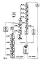
- FIG. 4 illustrates the operating method for the automatic setting of the stimulation intensity, that is to say the energy content of the stimulation pulses. Accordingly, there is no continuous adjustment of the stimulation intensity. Rather, most of the time the pacemaker is in an operating mode designated "NORMAL MODE", in which the second detector device (43) is switched off and the microprocessor (5) does not operate in any way to adjust the energy content of the stimulation pulses. This is done for reasons of energy saving and is possible without disadvantage for the patient, since the As a rule, the stimulus threshold changes only very slowly, so that it is sufficient to make an automatic adjustment of the energy content of the stimulation impulses at longer intervals. In the present case, this takes place at the first points in time, between which there is a time interval in the order of hours.
- the stimulation pulse generator (20) stimulates the heart with stimulation pulses of the energy content A that was set during the last automatic adjustment of the energy content.
- This energy content A is composed of the minimum energy content V, which corresponds to the stimulation threshold, and which is required to trigger a stimulated heartbeat which can be detected by the second detector device (43), and the safety marginal designated by M.
- an additional safety marginal N which can be, for example, 25% of the minimum energy content V, may also be present.
- STIM combined with the statement of a specific energy content A always means that a stimulation pulse of the respective energy content A is emitted.
- the detection of a stimulated heartbeat is illustrated in FIG. 4 by the statement DET, while the absence of detection of a stimulated heartbeat after a stimulation is indicated by the statement NO DET.
- Step I can be, for example, a certain fraction of the maximum possible energy content A max of the stimulation pulses. If this stimulation pulse also leads to the detection of a stimulated heartbeat, this means that the stimulation threshold has dropped. The last available value is therefore set as the new minimum energy content V reduced by step I and the new minimum energy content V increased by the safety marginal M as the new energy content A of the stimulation pulses. This is shown in Fig.
- the stimulus threshold it would be conceivable for the stimulus threshold to drop so far between two successive first times that a lowering of the minimum energy content V by more than one step I would be possible. Nevertheless, in the interest of the patient's safety, only a step I is lowered. Should the stimulus threshold actually stabilize at a level that permits a further reduction in the energy content A, the further reduction takes place early enough in the course of the next automatic setting (s) of the energy content A.
- a stimulation pulse with the maximum possible energy content A max is first emitted to ensure that no more than one stimulation pulse remains unsuccessful.
- the minimum energy content V is increased by a further step I. Before stimulation with the further increased minimum energy content V, however, there is first a stimulation with the maximum energy content A max . Only when a stimulated heartbeat is subsequently detected does the stimulation take place with the increased minimum energy content V. This is repeated until a minimum energy content V is found which leads to the detection of a stimulated heartbeat, whereupon the new energy content A for the "NORMAL MODE" is set as described immediately above, which is corresponding to the number of steps I and the additional safety marginal N higher than the previously available energy content A.
- the maximum energy content A max is set as energy content A for all further stimulations and the second detector device (43) is switched off.
- SIGNAL measures are taken which, when the programmer (37) next communicates with the pacemaker (1), result in a message being output by which the treating physician can recognize that an automatic Setting the energy content A of the stimulation pulses was not possible and therefore the maximum energy content A max was used.
- the next step is a stimulation with the maximum energy content A max .
- a new minimum energy content V and a new energy content A V + M + N of the stimulation pulses are set in the manner already described and this value is returned to "NORMAL MODE".
- the control described at the second points in time is also carried out in the interest of the patient's safety in order to be able to quickly take into account any disturbances or abnormal changes in the stimulus threshold.
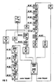
- the operating method shown in FIG. 5 for automatically adjusting the sensitivity of the first detector device (27) is similar to the operating method for automatically adjusting the energy content of the stimulation pulses.
- the pacemaker is in its "NORMAL MODE" mode of operation, in which the second detector device (43) is switched off.
- the adjustment of the sensitivity of the first detector device (27) this is possible without disadvantage for the patient, since the conditions do not generally change so quickly that a continuous adjustment of the sensitivity of the first detector device (27) would be necessary. It is therefore sufficient to set the sensitivity at the first points in time, between which there is a time interval with a duration in the order of hours.
- the first points in time for the automatic setting of the sensitivity of the first detector device (27) are expediently chosen such that they are immediately before or immediately after the first points in time at which the energy content of the stimulation pulses is set automatically.
- the sensitivity of the first detector device (27) corresponds to the sensitivity set in the last automatic setting.
- This sensitivity S is composed of the minimum sensitivity T, which is required in order to be able to also detect a natural heartbeat detected by means of the second detector device (43) with the first detector device (27), and the safety marginal denoted by X. Sensitivity. In special cases, which will be explained later, an additional safety marginal of sensitivity Y, e.g. 25% of the minimum sensitivity T may be present.
- the safety margins X and Y are subtracted from the minimum sensitivity T, since a higher sensitivity S generally corresponds to a smaller numerical value of the sensitivity S. 5, the indication SENSE combined with the indication of a specific sensitivity S always means that the sensitivity S of the first detector device (27) is set to the respective value.
- the detection of a natural heartbeat by means of the first detector device (27) is illustrated in FIG. 5 by the indication DET. If the first detector device (27) fails to detect a heartbeat detected by means of the second detector device (43), this is illustrated by the indication NO DET.
- Step E can be, for example, a certain fraction or a multiple of the maximum possible sensitivity S max of the first detector device (27).
- the sensitivity S is first set to its maximum value S max until the detection of the next natural heartbeat, but this is chosen such that disorders and muscle twitches do not lead to incorrect detection being able to lead. If the next natural heartbeat detected by means of the second detector device (43) is also detected with the first detector device (27) set to maximum sensitivity S max , the first detector device (27) is set to a sensitivity S that corresponds to the last one to the step E corresponds to increased minimum sensitivity T.
- the new minimum sensitivity T is set accordingly.
- S TXY in "NORMAL MODE". This is done so that in the event that a further increase in the minimum sensitivity T should become necessary, appropriate precautions are taken in the interest of the patient's safety.
- the additional safety marginal Y is again eliminated, as is evident from the above explanations.
- the minimum sensitivity T of the first detector device (27) increased by a step E is not sufficient to also detect a natural heartbeat detected by the second detector device (43), the minimum sensitivity T is increased by a further step E.
- the sensitivity of the first detector device (27) is set to its maximum value S max in order to enable the detection of the next natural heartbeat. Only when this detection has been carried out is it checked for the subsequent natural heartbeat detected by means of the second detector device (43) whether detection is also carried out by means of the first detector device (27) with the sensitivity S increased by a further step E. This is repeated until a new minimum sensitivity T is found, with which the first detector device (27) also detects a natural heartbeat detected by means of the second detector device (43). Then the new minimum sensitivity T and the new sensitivity S as described immediately above and set to "NORMAL MODE" with these values, in which case the safety marginal X and the additional safety marginal Y are present.
- the sensitivity S of the first detector device (27 ) set to their maximum value S max .
- measures are taken to ensure that the next time the programmer (37) communicates with the pacemaker (1), the attending physician is informed that the sensitivity of the first detector device (27) has been set to its maximum value S max .
- the first detector device (27) is deactivated and the second detector device (43) takes its place.
- the system returns to "NORMAL MODE". If the detection by means of the first detector device (27) fails to occur for one of the natural heartbeats, the minimum sensitivity T is first newly set, specifically to a value which corresponds to the sensitivity S previously present in "NORMAL MODE". This is followed by the determination of a new minimum sensitivity T in the manner already described above, and after the setting and setting of a new sensitivity S for the first detector device (27) the return to "NORMAL MODE".
- the first and second points in time are expediently determined by the microprocessor (5) counting a corresponding number of clock pulses generated by means of the quartz (14).
- Essential functions of the pacemaker according to the described embodiment are controlled by a suitably programmed microprocessor (5).
- the corresponding functions can also be easily implemented using a conventionally designed control logic.
- the described embodiment of the second detector device (43) is a preferred embodiment of this detector device.
- other suitable detector devices can also be used which likewise detect natural heartbeats in a signal corresponding to the temporal course of the electrical impedance of the heart or also another signal.
Priority Applications (4)
| Application Number | Priority Date | Filing Date | Title |
|---|---|---|---|
| DE89109157T DE58906041D1 (de) | 1989-05-22 | 1989-05-22 | Implantierbares medizinisches Gerät zur Detektion von bezüglich einer physiologischen Funktion auftretenden Ereignissen mit einstellbarer Empfindlichkeit und Verfahren zum Betrieb eines solchen Gerätes. |
| EP89109157A EP0399059B2 (fr) | 1989-05-22 | 1989-05-22 | Appareil médical implantable pour détecter un évènement relatif à une fonction physiologique à sensibilité réglable et son procédé d'utilisation |
| US07/525,133 US5050599A (en) | 1989-05-22 | 1990-05-17 | Implantable medical device for detecting events occurring with respect to a physiological function with variable sensitivity and a method for the operation of such a device |
| JP2132414A JPH034876A (ja) | 1989-05-22 | 1990-05-21 | 植え込み可能な医学装置 |
Applications Claiming Priority (1)
| Application Number | Priority Date | Filing Date | Title |
|---|---|---|---|
| EP89109157A EP0399059B2 (fr) | 1989-05-22 | 1989-05-22 | Appareil médical implantable pour détecter un évènement relatif à une fonction physiologique à sensibilité réglable et son procédé d'utilisation |
Publications (3)
| Publication Number | Publication Date |
|---|---|
| EP0399059A1 true EP0399059A1 (fr) | 1990-11-28 |
| EP0399059B1 EP0399059B1 (fr) | 1993-10-27 |
| EP0399059B2 EP0399059B2 (fr) | 2003-08-20 |
Family
ID=8201384
Family Applications (1)
| Application Number | Title | Priority Date | Filing Date |
|---|---|---|---|
| EP89109157A Expired - Lifetime EP0399059B2 (fr) | 1989-05-22 | 1989-05-22 | Appareil médical implantable pour détecter un évènement relatif à une fonction physiologique à sensibilité réglable et son procédé d'utilisation |
Country Status (4)
| Country | Link |
|---|---|
| US (1) | US5050599A (fr) |
| EP (1) | EP0399059B2 (fr) |
| JP (1) | JPH034876A (fr) |
| DE (1) | DE58906041D1 (fr) |
Cited By (9)
| Publication number | Priority date | Publication date | Assignee | Title |
|---|---|---|---|---|
| WO1993008873A1 (fr) * | 1991-10-31 | 1993-05-13 | Medtronic, Inc. | Reglage automatique de la sensibilite pour stimulateurs cardiaques |
| EP0653225A1 (fr) * | 1993-11-17 | 1995-05-17 | ELA MEDICAL (Société anonyme) | Procédé de commande automatique du seuil de détection du rythme cardiaque dans un appareil implantable |
| US10806428B2 (en) | 2015-02-12 | 2020-10-20 | Foundry Innovation & Research 1, Ltd. | Implantable devices and related methods for heart failure monitoring |
| US11039813B2 (en) | 2015-08-03 | 2021-06-22 | Foundry Innovation & Research 1, Ltd. | Devices and methods for measurement of Vena Cava dimensions, pressure and oxygen saturation |
| US11206992B2 (en) | 2016-08-11 | 2021-12-28 | Foundry Innovation & Research 1, Ltd. | Wireless resonant circuit and variable inductance vascular monitoring implants and anchoring structures therefore |
| US11564596B2 (en) | 2016-08-11 | 2023-01-31 | Foundry Innovation & Research 1, Ltd. | Systems and methods for patient fluid management |
| US11701018B2 (en) | 2016-08-11 | 2023-07-18 | Foundry Innovation & Research 1, Ltd. | Wireless resonant circuit and variable inductance vascular monitoring implants and anchoring structures therefore |
| US11779238B2 (en) | 2017-05-31 | 2023-10-10 | Foundry Innovation & Research 1, Ltd. | Implantable sensors for vascular monitoring |
| US11944495B2 (en) | 2017-05-31 | 2024-04-02 | Foundry Innovation & Research 1, Ltd. | Implantable ultrasonic vascular sensor |
Families Citing this family (13)
| Publication number | Priority date | Publication date | Assignee | Title |
|---|---|---|---|---|
| SE9203642D0 (sv) * | 1992-12-03 | 1992-12-03 | Siemens Elema Ab | Detekor foer avkaennande av haendelser i levande vaevnad |
| US5282839A (en) * | 1992-12-14 | 1994-02-01 | Medtronic, Inc. | Rate responsive cardiac pacemaker and method for providing an optimized pacing rate which varies with a patient's physiologic demand |
| US5476485A (en) * | 1993-09-21 | 1995-12-19 | Pacesetter, Inc. | Automatic implantable pulse generator |
| FR2714611B1 (fr) * | 1993-12-31 | 1996-03-15 | Ela Medical Sa | Procédé de contrôle d'un dispositif implantable actif. |
| SE9502430D0 (sv) * | 1995-07-04 | 1995-07-04 | Pacesetter Ab | Device for varying the threshold detection level of a sensor |
| US5620466A (en) * | 1995-08-14 | 1997-04-15 | Cardiac Pacemakers, Inc. | Digital AGC using separate gain control and threshold templating |
| US5658317A (en) * | 1995-08-14 | 1997-08-19 | Cardiac Pacemakers, Inc. | Threshold templating for digital AGC |
| US5662688A (en) * | 1995-08-14 | 1997-09-02 | Cardiac Pacemakers, Inc. | Slow gain control |
| US5800466A (en) * | 1997-04-14 | 1998-09-01 | Sulzer Intermedics Inc. | Dynamic atrial detection sensitivity control in an implantable medical cardiac simulator |
| US5755738A (en) * | 1997-04-22 | 1998-05-26 | Cardiac Pacemakers, Inc. | Automatic sensing level adjustment for implantable cardiac rhythm management devices |
| US6463334B1 (en) | 1998-11-02 | 2002-10-08 | Cardiac Pacemakers, Inc. | Extendable and retractable lead |
| US6501990B1 (en) | 1999-12-23 | 2002-12-31 | Cardiac Pacemakers, Inc. | Extendable and retractable lead having a snap-fit terminal connector |
| US6865414B1 (en) | 2001-09-20 | 2005-03-08 | Pacesetter, Inc. | Apparatus and method for automatically sensing threshold histogram with differentiation of sinus from ectopic beats |
Citations (5)
| Publication number | Priority date | Publication date | Assignee | Title |
|---|---|---|---|---|
| US4552154A (en) * | 1984-03-12 | 1985-11-12 | Medtronic, Inc. | Waveform morphology discriminator and method |
| EP0220916A2 (fr) * | 1985-10-25 | 1987-05-06 | David Wyn Davies | Appareil de détection et de correction de tachycardies et de fibrillations ventriculaires |
| US4766902A (en) * | 1986-06-04 | 1988-08-30 | Telectronics N.V. | Automatic sensitivity control for cardiac pacer |
| US4768511A (en) * | 1986-07-10 | 1988-09-06 | Telectronics N.V. | Automatic sensitivity control for implantable cardiac pacemakers |
| US4773401A (en) * | 1987-08-21 | 1988-09-27 | Cardiac Pacemakers, Inc. | Physiologic control of pacemaker rate using pre-ejection interval as the controlling parameter |
-
1989
- 1989-05-22 DE DE89109157T patent/DE58906041D1/de not_active Expired - Fee Related
- 1989-05-22 EP EP89109157A patent/EP0399059B2/fr not_active Expired - Lifetime
-
1990
- 1990-05-17 US US07/525,133 patent/US5050599A/en not_active Expired - Lifetime
- 1990-05-21 JP JP2132414A patent/JPH034876A/ja active Pending
Patent Citations (5)
| Publication number | Priority date | Publication date | Assignee | Title |
|---|---|---|---|---|
| US4552154A (en) * | 1984-03-12 | 1985-11-12 | Medtronic, Inc. | Waveform morphology discriminator and method |
| EP0220916A2 (fr) * | 1985-10-25 | 1987-05-06 | David Wyn Davies | Appareil de détection et de correction de tachycardies et de fibrillations ventriculaires |
| US4766902A (en) * | 1986-06-04 | 1988-08-30 | Telectronics N.V. | Automatic sensitivity control for cardiac pacer |
| US4768511A (en) * | 1986-07-10 | 1988-09-06 | Telectronics N.V. | Automatic sensitivity control for implantable cardiac pacemakers |
| US4773401A (en) * | 1987-08-21 | 1988-09-27 | Cardiac Pacemakers, Inc. | Physiologic control of pacemaker rate using pre-ejection interval as the controlling parameter |
Cited By (12)
| Publication number | Priority date | Publication date | Assignee | Title |
|---|---|---|---|---|
| WO1993008873A1 (fr) * | 1991-10-31 | 1993-05-13 | Medtronic, Inc. | Reglage automatique de la sensibilite pour stimulateurs cardiaques |
| EP0653225A1 (fr) * | 1993-11-17 | 1995-05-17 | ELA MEDICAL (Société anonyme) | Procédé de commande automatique du seuil de détection du rythme cardiaque dans un appareil implantable |
| FR2712500A1 (fr) * | 1993-11-17 | 1995-05-24 | Ela Medical Sa | Procédé de commande automatique du seuil de détection du rythme cardiaque dans un appareil implantable. |
| US5564430A (en) * | 1993-11-17 | 1996-10-15 | Ela Medical S.A. | Automatic control of the sensing threshold for monitoring cardiac rhythm in a implantable device |
| US10806428B2 (en) | 2015-02-12 | 2020-10-20 | Foundry Innovation & Research 1, Ltd. | Implantable devices and related methods for heart failure monitoring |
| US10905393B2 (en) | 2015-02-12 | 2021-02-02 | Foundry Innovation & Research 1, Ltd. | Implantable devices and related methods for heart failure monitoring |
| US11039813B2 (en) | 2015-08-03 | 2021-06-22 | Foundry Innovation & Research 1, Ltd. | Devices and methods for measurement of Vena Cava dimensions, pressure and oxygen saturation |
| US11206992B2 (en) | 2016-08-11 | 2021-12-28 | Foundry Innovation & Research 1, Ltd. | Wireless resonant circuit and variable inductance vascular monitoring implants and anchoring structures therefore |
| US11564596B2 (en) | 2016-08-11 | 2023-01-31 | Foundry Innovation & Research 1, Ltd. | Systems and methods for patient fluid management |
| US11701018B2 (en) | 2016-08-11 | 2023-07-18 | Foundry Innovation & Research 1, Ltd. | Wireless resonant circuit and variable inductance vascular monitoring implants and anchoring structures therefore |
| US11779238B2 (en) | 2017-05-31 | 2023-10-10 | Foundry Innovation & Research 1, Ltd. | Implantable sensors for vascular monitoring |
| US11944495B2 (en) | 2017-05-31 | 2024-04-02 | Foundry Innovation & Research 1, Ltd. | Implantable ultrasonic vascular sensor |
Also Published As
| Publication number | Publication date |
|---|---|
| JPH034876A (ja) | 1991-01-10 |
| EP0399059B2 (fr) | 2003-08-20 |
| DE58906041D1 (de) | 1993-12-02 |
| EP0399059B1 (fr) | 1993-10-27 |
| US5050599A (en) | 1991-09-24 |
Similar Documents
| Publication | Publication Date | Title |
|---|---|---|
| EP0399063B1 (fr) | Appareil médical implantable pour stimuler des contractions dans les tissus avec une intensité de stimulation réglable et son procédé d'utilisation | |
| EP0399059B1 (fr) | Appareil médical implantable pour détecter un évènement relatif à une fonction physiologique à sensibilité réglable et son procédé d'utilisation | |
| DE69832639T2 (de) | Implantierbares Herzschrittmachersystem | |
| DE60222071T2 (de) | Implantierbares Herzschrittmachersystem mit Kalibrierung für automatische Erregungsbestätigung | |
| DE3046681C2 (fr) | ||
| DE69531115T2 (de) | Herzschrittmacher mit Detektion einer erfolgreichen Stimulation des Ventrikel und Suche nach dem Stimulation-Schwellenwert | |
| EP0392032B1 (fr) | Appareil médical implantable comportant des moyens de transmission télémétrique de données | |
| EP0422271B1 (fr) | Appareil médical implantable dans le corps d'un être vivant comportant des moyens de stimulation de contraction de tissus | |
| DE69827420T2 (de) | Herzschrittmacher mit variabler Stimulationsenergie | |
| EP0416138A1 (fr) | Appareil médical coopérant avec le corps d'un être vivant pour la stimulation et/ou la surveillance d'une fonction physiologique | |
| DE3831809A1 (de) | Zur mindestens teilweisen implantation im lebenden koerper bestimmtes geraet | |
| EP0464252B1 (fr) | Dispositif de stimulation de tissus | |
| DE60308203T2 (de) | Gerät zur bestimmung des stimulationschwellwertes | |
| EP0063097A1 (fr) | Stimulateur cardiaque | |
| DE2254928A1 (de) | Herzschrittmacher | |
| EP0783902A2 (fr) | Dispositif de contrÔle extracorporel pour un dispositif médical implantable | |
| WO1991016102A1 (fr) | Stimulateur de tissus | |
| EP0414928B1 (fr) | Appareil médical de stimulation d'un processus physiologique dans un corps vivant où l'intensité de stimulation est automatiquement adaptée à l'activité corporelle | |
| EP2676697B1 (fr) | Capteur de dislocation | |
| EP0490985B1 (fr) | Appareil medical pour stimuler les contractions tissulaires | |
| DE60307767T2 (de) | Implantierbarer Herzschrittmacher und System mit einem solchem Gerät | |
| DE69532500T2 (de) | Herzschrittmacher mit detektion eines vasoneurotischen kollapses | |
| DE60013608T2 (de) | Herzschrittmacher | |
| DE10003339A1 (de) | Schrittmachersystem mit vereinfachter Detektion der Anbindung an den Herzvorhof, basierend auf dem QT-Intervall | |
| DE4416779B4 (de) | Vorrichtung zur Vermeidung des zeitlichen Zusammenfallens von stimulierten und spontanen Herzreaktionen |
Legal Events
| Date | Code | Title | Description |
|---|---|---|---|
| PUAI | Public reference made under article 153(3) epc to a published international application that has entered the european phase |
Free format text: ORIGINAL CODE: 0009012 |
|
| AK | Designated contracting states |
Kind code of ref document: A1 Designated state(s): DE FR GB IT NL SE |
|
| 17P | Request for examination filed |
Effective date: 19901205 |
|
| 17Q | First examination report despatched |
Effective date: 19930401 |
|
| GRAA | (expected) grant |
Free format text: ORIGINAL CODE: 0009210 |
|
| AK | Designated contracting states |
Kind code of ref document: B1 Designated state(s): DE FR GB IT NL SE |
|
| PG25 | Lapsed in a contracting state [announced via postgrant information from national office to epo] |
Ref country code: SE Effective date: 19931027 |
|
| REF | Corresponds to: |
Ref document number: 58906041 Country of ref document: DE Date of ref document: 19931202 |
|
| ITF | It: translation for a ep patent filed |
Owner name: STUDIO JAUMANN |
|
| ET | Fr: translation filed | ||
| GBT | Gb: translation of ep patent filed (gb section 77(6)(a)/1977) |
Effective date: 19940107 |
|
| PLBE | No opposition filed within time limit |
Free format text: ORIGINAL CODE: 0009261 |
|
| PLBE | No opposition filed within time limit |
Free format text: ORIGINAL CODE: 0009261 |
|
| PLBI | Opposition filed |
Free format text: ORIGINAL CODE: 0009260 |
|
| PLAA | Information modified related to event that no opposition was filed |
Free format text: ORIGINAL CODE: 0009299DELT |
|
| 26N | No opposition filed | ||
| 26 | Opposition filed |
Opponent name: BIOTRONIK MESS- UND THERAPIEGERAETE GMBH & CO INGE Effective date: 19940727 |
|
| 26N | No opposition filed | ||
| NLR1 | Nl: opposition has been filed with the epo |
Opponent name: BIOTRONIK MESS- UND THERAPIEGERAETE GMBH & CO. |
|
| RAP2 | Party data changed (patent owner data changed or rights of a patent transferred) |
Owner name: PACESETTER AB |
|
| ITPR | It: changes in ownership of a european patent |
Owner name: CESSIONE;PACESETTER AB |
|
| REG | Reference to a national code |
Ref country code: GB Ref legal event code: 732E |
|
| REG | Reference to a national code |
Ref country code: FR Ref legal event code: TP |
|
| NLT2 | Nl: modifications (of names), taken from the european patent patent bulletin |
Owner name: PACESETTER AB TE SOLNA, ZWEDEN. |
|
| NLS | Nl: assignments of ep-patents |
Owner name: PACESETTER AB |
|
| PLBO | Opposition rejected |
Free format text: ORIGINAL CODE: EPIDOS REJO |
|
| RAP2 | Party data changed (patent owner data changed or rights of a patent transferred) |
Owner name: PACESETTER AB |
|
| PGFP | Annual fee paid to national office [announced via postgrant information from national office to epo] |
Ref country code: GB Payment date: 19980414 Year of fee payment: 10 |
|
| NLT2 | Nl: modifications (of names), taken from the european patent patent bulletin |
Owner name: PACESETTER AB |
|
| APAC | Appeal dossier modified |
Free format text: ORIGINAL CODE: EPIDOS NOAPO |
|
| APAE | Appeal reference modified |
Free format text: ORIGINAL CODE: EPIDOS REFNO |
|
| APAC | Appeal dossier modified |
Free format text: ORIGINAL CODE: EPIDOS NOAPO |
|
| PG25 | Lapsed in a contracting state [announced via postgrant information from national office to epo] |
Ref country code: GB Free format text: LAPSE BECAUSE OF NON-PAYMENT OF DUE FEES Effective date: 19990522 |
|
| PGFP | Annual fee paid to national office [announced via postgrant information from national office to epo] |
Ref country code: NL Payment date: 19990531 Year of fee payment: 11 |
|
| GBPC | Gb: european patent ceased through non-payment of renewal fee |
Effective date: 19990522 |
|
| PG25 | Lapsed in a contracting state [announced via postgrant information from national office to epo] |
Ref country code: NL Free format text: LAPSE BECAUSE OF NON-PAYMENT OF DUE FEES Effective date: 20001201 |
|
| RAP2 | Party data changed (patent owner data changed or rights of a patent transferred) |
Owner name: ST. JUDE MEDICAL AB |
|
| PLBQ | Unpublished change to opponent data |
Free format text: ORIGINAL CODE: EPIDOS OPPO |
|
| NLV4 | Nl: lapsed or anulled due to non-payment of the annual fee |
Effective date: 20001201 |
|
| PLAB | Opposition data, opponent's data or that of the opponent's representative modified |
Free format text: ORIGINAL CODE: 0009299OPPO |
|
| R26 | Opposition filed (corrected) |
Opponent name: BIOTRONIK MESS- UND THERAPIEGERAETE GMBH & CO INGE Effective date: 19940727 |
|
| APAC | Appeal dossier modified |
Free format text: ORIGINAL CODE: EPIDOS NOAPO |
|
| PLAW | Interlocutory decision in opposition |
Free format text: ORIGINAL CODE: EPIDOS IDOP |
|
| PUAH | Patent maintained in amended form |
Free format text: ORIGINAL CODE: 0009272 |
|
| STAA | Information on the status of an ep patent application or granted ep patent |
Free format text: STATUS: PATENT MAINTAINED AS AMENDED |
|
| 27A | Patent maintained in amended form |
Effective date: 20030820 |
|
| AK | Designated contracting states |
Designated state(s): DE FR GB IT NL SE |
|
| ET3 | Fr: translation filed ** decision concerning opposition | ||
| APAH | Appeal reference modified |
Free format text: ORIGINAL CODE: EPIDOSCREFNO |
|
| PGFP | Annual fee paid to national office [announced via postgrant information from national office to epo] |
Ref country code: DE Payment date: 20070524 Year of fee payment: 19 |
|
| PGFP | Annual fee paid to national office [announced via postgrant information from national office to epo] |
Ref country code: IT Payment date: 20070530 Year of fee payment: 19 |
|
| PGFP | Annual fee paid to national office [announced via postgrant information from national office to epo] |
Ref country code: FR Payment date: 20070430 Year of fee payment: 19 |
|
| REG | Reference to a national code |
Ref country code: FR Ref legal event code: ST Effective date: 20090119 |
|
| PG25 | Lapsed in a contracting state [announced via postgrant information from national office to epo] |
Ref country code: FR Free format text: LAPSE BECAUSE OF NON-PAYMENT OF DUE FEES Effective date: 20080602 Ref country code: DE Free format text: LAPSE BECAUSE OF NON-PAYMENT OF DUE FEES Effective date: 20081202 |
|
| PG25 | Lapsed in a contracting state [announced via postgrant information from national office to epo] |
Ref country code: IT Free format text: LAPSE BECAUSE OF NON-PAYMENT OF DUE FEES Effective date: 20080522 |