EP0397692B1 - Hydrostatische hilfskraft-lenkeinrichtung, insbesondere für kraftfahrzeuge - Google Patents
Hydrostatische hilfskraft-lenkeinrichtung, insbesondere für kraftfahrzeuge Download PDFInfo
- Publication number
- EP0397692B1 EP0397692B1 EP19890900808 EP89900808A EP0397692B1 EP 0397692 B1 EP0397692 B1 EP 0397692B1 EP 19890900808 EP19890900808 EP 19890900808 EP 89900808 A EP89900808 A EP 89900808A EP 0397692 B1 EP0397692 B1 EP 0397692B1
- Authority
- EP
- European Patent Office
- Prior art keywords
- section
- control valve
- piston
- line
- cross
- Prior art date
- Legal status (The legal status is an assumption and is not a legal conclusion. Google has not performed a legal analysis and makes no representation as to the accuracy of the status listed.)
- Expired - Lifetime
Links
- 230000002706 hydrostatic effect Effects 0.000 title claims abstract description 10
- 238000006073 displacement reaction Methods 0.000 claims abstract description 15
- 230000007935 neutral effect Effects 0.000 claims abstract description 15
- 230000001419 dependent effect Effects 0.000 description 5
- 238000010438 heat treatment Methods 0.000 description 1
- 230000001105 regulatory effect Effects 0.000 description 1
- 238000009966 trimming Methods 0.000 description 1
Images

Classifications
-
- B—PERFORMING OPERATIONS; TRANSPORTING
- B62—LAND VEHICLES FOR TRAVELLING OTHERWISE THAN ON RAILS
- B62D—MOTOR VEHICLES; TRAILERS
- B62D5/00—Power-assisted or power-driven steering
- B62D5/06—Power-assisted or power-driven steering fluid, i.e. using a pressurised fluid for most or all the force required for steering a vehicle
- B62D5/09—Power-assisted or power-driven steering fluid, i.e. using a pressurised fluid for most or all the force required for steering a vehicle characterised by means for actuating valves
- B62D5/093—Telemotor driven by steering wheel movement
- B62D5/097—Telemotor driven by steering wheel movement gerotor type
Definitions
- the invention relates to a hydrostatic power steering device, in particular for motor vehicles.
- An orifice is arranged in the pressure line, by means of the pressure difference of which an adjusting device of the variable pump or the flow control valve can be actuated.
- the inflow from the pressure line into the valve bore is controlled via a central piston collar which is arranged on a valve piston which is displaceably mounted in the valve bore.
- Such a hydrostatic power steering device is known, for example, from DE-PS 31 32 342. With such a steering device, the pressure medium flow is fed to the preferential steering system depending on the load.
- the panel for load-dependent power allocation is designed with a constant cross-section.
- a constant pilot flow is conveyed via the orifice.
- the pilot current must then be throttled to regulate a pressure that corresponds to the steering resistance.
- the pressure increases with increasing valve adjustment.
- pressure medium is branched off in front of the orifice and fed to the steering motor via the metering device. This causes the pressure difference across the orifice changed so that the adjustment of the variable pump starts.
- the variable displacement pump will only get a control signal when the control valve is almost fully deflected. The late control signal leads to dynamic problems, e.g. B. vibrations in the steering system.
- the invention has for its object to improve the known hydrostatic power steering device in such a way that a control signal is supplied to the variable pump early, regardless of the steering resistance.
- the new device is to be accommodated within the dimensions of the known control valve device.
- the orifice plate has a cross section that can be changed as a function of the switching position of the control valve, which has its smallest value in the neutral central position of the control valve and can be enlarged in both directions when the valve is adjusted.
- the variable orifice and its control means can be accommodated in the dimensions of the known control valve device. As a result of the arrangement and configuration of the diaphragm according to the invention, a control signal is fed to the variable displacement pump even after a very small adjustment path of the control valve, so that the variable displacement pump can be controlled without vibration.
- the pressure line is in the neutral middle position of the control valve device closed. In this position, the smallest cross-section of the aperture has the value zero.
- the section of the pressure line behind the orifice and the control line are expediently connected to the piston bore by a common connection which is located in the region of the central piston collar. If the width of the central piston collar is designed to be smaller than the smallest axial extent of the cross section of the common connection, the control line is simply connected to the return line in the neutral central position of the control valve device.
- the central piston collar is expediently provided with a circumferential groove on its circumference. This makes it possible to connect the cross-section of the outlet of the pressure line into the valve bore with the common connection for the section of the pressure line behind the orifice and the control line and thus with the return line.
- an internally toothed toothed ring 1 is arranged between a cover 2 and a deflection intermediate ring 3 of a housing 4 and is connected to this and a further end cover 5 by screws, not shown.
- An externally toothed gear 6 has one tooth less than the toothed ring 1 and, together with the latter, forms a metering device 7 in the form of a manual gear pump.
- Displacement chambers 8 are formed between the teeth of the toothed ring 1 and gear 6 and the end faces of the cover 2 and the intermediate deflection ring 3 adjoining the two parts.
- the gear wheel 6 is connected to a drive shaft 12 via a cardan shaft 10 and a driving pin 11 with backlash.
- the drive shaft 12 carries a hollow actuating sleeve 13.
- a valve piston 15 is mounted coaxially to the actuating sleeve 13 in a valve bore 14 arranged in the housing 4.
- the valve piston 15 is axially displaceable in both directions by means of steep thread profiles 16 arranged between the actuating sleeve 13 and the valve piston 15 when the drive shaft 12 rotates.
- a spring element 17 is arranged between the propeller shaft 10 and the drive shaft 12.
- the valve piston 15 forms a control valve device 18 in the valve bore 14 together with the surrounding parts. Grooves for the control of the pressure medium to and from the displacement chambers 8 of the metering device 7 and to and from the are in a known manner on the valve piston 15 and in the valve bore 14 Pressure chambers of a steering motor 20 arranged.
- the valve piston 15 has a central piston collar 21 and adjacent thereto a piston groove 22 or 23, which are delimited by another piston collar 24 or 25.
- variable pump a high pressure pump 28 with a variable delivery volume (hereinafter referred to as "variable pump") is directed.
- the junction 26 is located in a cylindrical housing web 31, to each of which a return groove 32 or 33 connects.
- the return grooves 32 and 33 are connected to the pressure medium container 30 via a return line 34.
- a diaphragm 35 in the form of two variable control openings 35A and 35B is formed between the cross section of the opening 26 of the pressure line 27 into the valve bore 14 and the central piston collar 21.
- the control openings 35A and 35B and thus the diaphragm 35 are closed in the neutral central position of the valve piston 15.
- the orifice 35 serves to generate a pressure difference which is required for the adjustment of the variable displacement pump 28.
- a common connection 36 opens into the valve bore 14 for a section 37 of the pressure line 27 behind the orifice 35 and for a control line 38.
- the pressure behind the orifice 35 is passed to the control line 38 Transfer adjustment device 40 of the adjustment pump 28.
- a constant displacement pump with a flow-dependent valve which can be adjusted as a function of the load can be provided.
- the width of the central piston collar 21 is smaller than the smallest axial extension of the cross section of the common connection 36.
- the width of the cylindrical housing web 31 is smaller than the distance between the two piston collars 24 and 25. This ensures that the control line 38 in the neutral central position of the valve piston 15 is connected to the pressure medium container 30 via the piston grooves 22 and 23, the return grooves 32 and 33 and the return line 34.
- a circumferential row of distributor longitudinal grooves 41 and 42 is arranged, which are connected to one of two pressure spaces 43 and 44 adjacent to the valve piston 15 at the end when the valve piston 15 is axially displaced.
- the longitudinal distribution grooves 41 and 42 also serve as commutation grooves and are connected via two lines 45 and 46 in a known manner to the pressure chambers 8 of the metering device 7.
- junction 26 in one plane and the common connection 36 in opposite directions in each case twice.
- the second embodiment shown in FIG. 3 differs from the first embodiment shown in FIGS. 1 and 2 only in that the orifice here is not completely closed in the neutral central position of the control valve device 18, but has a small minimum cross section.
- a circumferential groove 47 is attached to the central piston collar 21 of the valve piston 15, through which a connection is created from the mouth 26 of the pressure line 27 into the valve bore 14 to the common connection 36.
- variable displacement pump 28 is designed such that it tries to maintain a constant pressure difference between the pressure line 27 and the control line 38. Since the axial extent of the confluence cross section 26 of the pressure line 27 into the valve bore 14 is smaller than the width of the central piston collar 21, this is possible in the neutral central position of the valve piston 15 with a pressure medium flow of the variable displacement pump 28 approaching zero, and precisely because of the Connection cross section between the pressure line 27 and the control line 38 also goes to zero. The connection of the control line 38 to the pressure medium container 30 is required in the neutral central position of the valve piston 15 so that the pressure difference can be maintained at an overall low pressure level.
- valve piston 15 If the valve piston 15 is moved to the left, for example, the connection from the piston groove 22 to the common connection 36 and between the piston groove 23 and the return groove 33 is interrupted. The connection from the control line 38 to the pressure medium container 30 is thus disconnected. At approximately the same time, the connection from the mouth 26 of the pressure line 27 to the piston groove 23 is established. As a result, the pressure line 27 is connected to the control line 38 via the control opening 35B with a cross section dependent on the position of the valve piston 15. The control opening 35B forms the variable diaphragm 35, as described above. In order to maintain the constant pressure difference between the pressure line 27 and the control line 38, a pressure medium flow dependent on the cross section of the diaphragm 35 must flow via the diaphragm 35.
- This flow of pressure medium flows via the piston groove 23, the common connection 36 and the section 37 of the pressure line 27 behind the orifice 35 to the right-hand end pressure chamber 44, inside through the valve piston 15 to the left-hand end pressure chamber 43. From there the pressure medium is transferred the left longitudinal distribution grooves 41 and the line 45 passed to the metering device 7. From the displacement chambers 8 on the discharge side of the metering device 7, the pressure medium is supplied to the steering motor 20 in a known manner via the line 46 and the right commutation grooves 42. Without taking flow losses into account, the pressure in the pressure line 27 changes according to the resistance on the steering motor Set 20. With the valve piston 15 deflected to the maximum, the orifice 35 has reached its maximum cross section. A connection of the mouth 26 of the pressure line 27 into the valve bore 14 and the common connection 36 with the return grooves 32 or 33 is excluded because of the arrangement of the piston collars 24 and 25 described above.
Landscapes
- Engineering & Computer Science (AREA)
- Chemical & Material Sciences (AREA)
- Combustion & Propulsion (AREA)
- Transportation (AREA)
- Mechanical Engineering (AREA)
- Power Steering Mechanism (AREA)
- Valve Housings (AREA)
Description
- Die Erfindung betrifft eine hydrostatische Hilfskraft-Lenkeinrichtung, insbesondere für Kraftfahrzeuge, nach dem Oberbegriff des Anspruches 1. Die Hilfskraft-Lenkeinrichtung enthält eine Dosiereinrichtung und eine Steuerventileinrichtung, die das von einer Verstellpumpe bzw. von einer Konstantpumpe über ein Stromteilventil geförderte Druckmittel einem Lenkmotor zusteuert. In der Druckleitung ist eine Blende angeordnet, durch deren Druckdifferenz eine Verstelleinrichtung der Verstellpumpe bzw. des Stromteilventils betätigbar ist. Der Zulauf aus der Druckleitung in die Ventilbohrung wird dabei über einen zentralen Kolbenbund gesteuert, der an einem in der Ventilbohrung verschiebbar gelagerten Ventilkolben angeordnet ist.
- Eine derartige hydrostatische Hilfskraft-Lenkeinrichtung ist beispielsweise bekannt aus der DE-PS 31 32 342. Mit einer solchen Lenkeinrichtung wird der Druckmittelstrom lastabhängig der bevorrechtigten Lenkung zugeführt. Dabei ist die Blende für die lastabhängige Leistungszuteilung mit konstantem Querschnitt ausgeführt.
- Über die Blende wird in Neutralstellung der Steuerventileinrichtung ein ständiger Pilotstrom gefördert. Bei einer Verstellung der Steuerventileinrichtung werden bereits nach einem kleinen Ventilverstellweg die Verbindungen zu der Dosiereinrichtung und zu dem Lenkmotor gesteuert. Der Pilotstrom muß dann gedrosselt werden, damit ein Druck angeregelt wird, der dem Lenkwiderstand entspricht. Der Druck steigt mit zunehmender Ventilverstellung an. Wenn der angeregelte Druck den Lenkwiderstand überwindet, so wird vor der Blende Druckmittel abgezweigt und über die Dosiereinrichtung dem Lenkmotor zugeführt. Dadurch wird die Druckdifferenz über der Blende verändert, so daß die Verstellung der Verstellpumpe einsetzt. Bei hohen Lenkwiderständen wird die Verstellpumpe erst bei nahezu vollständig ausgelenktem Steuerventil ein Regelsignal bekommen. Das späte Regelsignal führt zu dynamischen Problemen, z. B. zu Schwingungen im Lenksystem.
- Der Erfindung liegt die Aufgabe zugrunde, die bekannte hydrostatische Hilfskraft-Lenkeinrichtung derart zu verbessern, daß der Verstellpumpe unabhängig vom Lenkwiderstand bereits frühzeitig ein Regelsignal zugeführt wird. Dabei soll die neue Einrichtung innerhalb der Abmessungen der bekannten Steuerventileinrichtung untergebracht werden.
- Diese Aufgabe wird erfindungsgemäß durch die im Anspruch 1 gekennzeichnete hydrostatische Hilfskraft-Lenkeinrichtung gelöst. Dabei weist die Blende einen in Abhängigkeit von der Schaltstellung des Steuerventils veränderbaren Querschnitt auf, der in der neutralen Mittelstellung des Steuerventils seinen kleinsten Wert besitzt und bei einer Verstellung des Ventils in beiden Richtungen vergrößerbar ist. Dies wird dadurch erreicht, daß die Blende zwischen dem Einmündungsquerschnitt der Druckleitung in die Ventilbohrung und dem zentralen Kolbenbund gebildet ist. Da der Ventilkolben hinsichtlich der Blende nach beiden Richtungen symmetrisch ausgebildet ist, ist die Veränderung des Blendenquerschnittes in beiden Lenkrichtungen gleich. Die veränderbare Blende und ihre Steuerungsmittel können in den Abmessungen der bekannten Steuerventileinrichtung untergebracht werden. Durch die erfindungsgemäße Anordnung und Ausgestaltung der Blende wird der Verstellpumpe bereits nach einem sehr kleinen Verstellweg des Steuerventils ein Regelsignal zugeleitet, so daß eine schwingungsfreie Regelung der Verstellpumpe möglich ist.
- Wird die Breite des zentralen Kolbenbundes größer ausgeführt als die größte axiale Erstreckung des Einmündungsquerschnitts der Druckleitung in die Ventilbohrung, so ist die Druckleitung in der neutralen Mittelstellung der Steuerventileinrichtung geschlossen. Der kleinste Querschnitt der Blende hat in dieser Stellung den Wert Null. Zweckmäßigerweise wird der hinter der Blende liegende Abschnitt der Druckleitung und die Steuerleitung durch einen gemeinsamen Anschluß, der im Bereich des zentralen Kolbenbundes liegt, an die Kolbenbohrung angeschlossen. Wird dabei die Breite des zentralen Kolbenbundes kleiner ausgelegt als die kleinste axiale Erstreckung des Querschnittes des gemeinsamen Anschlusses, so wird auf einfache Weise die Steuerleitung in der neutralen Mittelstellung der Steuerventileinrichtung mit der Rücklaufleitung verbunden.
- Soll die erfindungsgemäße Einrichtung bei einer hydrostatischen Hilfskraft-Lenkeinrichtung eingesetzt werden, bei der auch in der neutralen Mittelstellung ein kleiner Kurzschlußölstrom zur Erwärmung durch die Steuerventileinrichtung geführt werden soll, so wird zweckmäßigerweise der zentrale Kolbenbund an seinem Umfang mit einem umlaufenden Einstich versehen. Dadurch ist eine Verbindung des Einmündungsquerschnittes der Druckleitung in die Ventilbohrung mit dem gemeinsamen Anschluß für den hinter der Blende liegenden Abschnitt der Druckleitung und die Steuerleitung und damit mit der Rücklaufleitung möglich.
- Im folgenden wird die Erfindung anhand zweier in der Zeichnung dargestellter Ausführungsbeispiele näher erläutert. Es zeigen:
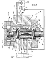
- Fig. 1 einen Querschnitt durch die erfindungsgemäße hydrostatische Hilfskraft-Lenkeinrichtung, teilweise in schematischer Darstellung;
- Fig. 2 einen Querschnitt durch die Steuerventileinrichtung eines ersten Ausführungsbeispieles in vereinfachter Darstellung;
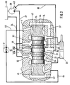
- Fig. 3 einen Querschnitt durch die Steuerventileinrichtung eines zweiten Ausführungsbeispieles in vereinfachter Darstellung.
- In der erfindungsgemäßen hydrostatischen Hilfskraft-Lenkeinrichtung ist ein innenverzahnter Zahnring 1 zwischen einem Deckel 2 und einem Umlenkzwischenring 3 eines Gehäuses 4 angeordnet und mit diesem und einem weiteren Abschlußdeckel 5 durch nicht dargestellte Schrauben verbunden. Ein außenverzahntes Zahnrad 6 weist einen Zahn weniger als der Zahnring 1 auf und bildet zusammen mit diesem eine Dosiereinrichtung 7 in der Form einer Handzahnradpumpe. Zwischen den Zähnen von Zahnring 1 und Zahnrad 6 und den an den beiden Teilen angrenzenden Stirnflächen des Deckels 2 und des Umlenkzwischenringes 3 werden Verdrängerkammern 8 gebildet.
- Das Zahnrad 6 ist über eine Gelenkwelle 10 und einen Mitnehmerstift 11 mit Verdrehspiel mit einer Antriebswelle 12 verbunden. Die Antriebswelle 12 trägt eine hohle Betätigungshülse 13.
- In einer in dem Gehäuse 4 angeordneten Ventilbohrung 14 ist ein Ventilkolben 15 koaxial zu der Betätigungshülse 13 gelagert. Der Ventilkolben 15 ist über zwischen der Betätigungshülse 13 und dem Ventilkolben 15 angeordnete Steilgewindeprofile 16 bei einer Drehbewegung der Antriebswelle 12 in beiden Richtungen axial verschiebbar. Zwischen der Gelenkwelle 10 und der Antriebswelle 12 ist ein Federelement 17 angeordnet.
- Der Ventilkolben 15 bildet in der Ventilbohrung 14 zusammen mit den umgebenden Teilen eine Steuerventileinrichtung 18. An dem Ventilkolben 15 und in der Ventilbohrung 14 sind in bekannter Weise Nuten für die Steuerung des Druckmittels zu und von den Verdrängerkammern 8 der Dosiereinrichtung 7 und zu und von den Druckräumen eines Lenkmotors 20 angeordnet. Für die erfindungsgemäße Funktion der Lenkeinrichtung ist von Bedeutung, daß der Ventilkolben 15 einen zentralen Kolbenbund 21 und benachbart dazu je eine Kolbennut 22 bzw. 23 aufweist, die durch je einen weiteren Kolbenbund 24 bzw. 25 begrenzt sind. Im Bereich der axialen Erstreckung des zentralen Kolbenbundes 21 ist eine zu der Ventilbohrung 14 führende Einmündung 26 einer Druckleitung 27 angeordnet, durch die von einer Hochdruckpumpe 28 mit veränderbarem Fördervolumen (im folgenden kurz "Verstellpumpe" genannt) Druckmittel aus einem Druckmittelbehälter 30 zu der Steuerventileinrichtung 18 geleitet wird. Die Einmündung 26 befindet sich in einem zylindrischen Gehäusesteg 31, an den sich beiderseits je eine Rücklaufnut 32 bzw. 33 anschließt. Die Rücklaufnuten 32 und 33 stehen über eine Rücklaufleitung 34 mit dem Druckmittelbehälter 30 in Verbindung.
- Zwischen dem Querschnitt der Einmündung 26 der Druckleitung 27 in die Ventilbohrung 14 und dem zentralen Kolbenbund 21 ist eine Blende 35 in der Form von zwei veränderbaren Steueröffnungen 35A und 35B gebildet. Die Steueröffnungen 35A und 35B und damit die Blende 35 sind in der neutralen Mittelstellung des Ventilkolbens 15 geschlossen.
- Die Blende 35 dient zur Erzeugung einer Druckdifferenz, die für die Verstellung der Verstellpumpe 28 benötigt wird. Im Bereich der axialen Erstreckung des zentralen Kolbenbundes 21 mündet in die Ventilbohrung 14 ein gemeinsamer Anschluß 36 für einen hinter der Blende 35 liegenden Abschnitt 37 der Druckleitung 27 und für eine Steuerleitung 38. Über die Steuerleitung 38 wird der hinter der Blende 35 herrschende Druck an eine Verstelleinrichtung 40 der Verstellpumpe 28 übertragen. Anstelle der Verstellpumpe 28 kann eine Kontantpumpe mit einem lastabhängig verstellbaren Stromteilventil vorgesehen werden.
- Die Breite des zentralen Kolbenbundes 21 ist kleiner als die kleinste axiale Erstreckung des Querschnittes des gemeinsamen Anschlusses 36. Die Breite des zylindrischen Gehäusesteges 31 ist kleiner als der Abstand der beiden Kolbenbunde 24 und 25. Dadurch ist gewährleistet, daß die Steuerleitung 38 in der neutralen Mittelstellung des Ventilkolbens 15 über die Kolbennuten 22 und 23, die Rücklaufnuten 32 und 33 und die Rücklaufleitung 34 mit dem Druckmittelbehälter 30 verbunden ist.
- An den beiden Enden des Ventilkolbens 15 ist je eine Umfangsreihe von Verteilerlängsnuten 41 bzw. 42 angeordnet, die bei einer Axialverschiebung des Ventilkolbens 15 mit einem von zwei stirnseitig an den Ventilkolben 15 angrenzenden Druckräumen 43 bzw. 44 verbunden werden. Die Verteilerlängsnuten 41 und 42 dienen außerdem als Kommutierungsnuten und sind über zwei Leitungen 45 und 46 in bekannter Weise an die Druckkammern 8 der Dosiereinrichtung 7 angeschlossen.
- Um einen vollständigen radialen Druckausgleich in der Steuerventileinrichtung 18 zu erreichen, ist es zweckmäßig, in einer Ebene die Einmündung 26 und in einer anderen Ebene den gemeinsamen Anschluß 36 jeweils zweimal gegenüberliegend auszuführen.
- Das zweite, in Fig. 3 dargestellte Ausführungsbeispiel unterscheidet sich von dem ersten in den Fig. 1 und 2 dargestellten Ausführungsbeispiel nur dadurch, daß die Blende hier in der neutralen Mittelstellung der Steuerventileinrichtung 18 nicht vollständig geschlossen ist, sondern einen geringen Mindestquerschnitt besitzt. Dazu ist an dem zentralen Kolbenbund 21 des Ventilkolbens 15 ein umlaufender Einstich 47 angebracht, durch den eine Verbindung geschaffen wird von der Einmündung 26 der Druckleitung 27 in die Ventilbohrung 14 zu dem gemeinsamen Anschluß 36. Über dem Einstich 47 fließt bei nicht betätigter Lenkung ein von dem Querschnitt des Einstiches 47 abhängiger Druckmittelstrom zum Temperieren durch die Steuerventileinrichtung 18.
- Es wäre vorstellbar, eine derartige Kurzschlußverbindung durch die Steuerventileinrichtung 18 dadurch herzustellen, daß die axiale Erstreckung des Querschnittes der Einmündung 26 in die Ventilbohrung 14 größer ist als die Breite des zentralen Kolbenbundes 21. Bei einer solchen Anordnung ist jedoch die Größe des Verbindungsquerschnittes zwischen der Einmündung 26 und dem gemeinsamen Anschluß 36 von der exakten Mittelstellung des Ventilkolbens 15 abhängig. Bei einem Einstich 47 ist der Querschnitt unabhängig von der exakten Mittelstellung des Ventilkolbens 15.
- Im folgenden wird die Funktion der Lenkeinrichtung anhand des Ausführungsbeispieles der Fig. 2 näher beschrieben. Die Verstellpumpe 28 ist so ausgeführt, daß sie versucht, zwischen der Druckleitung 27 und der Steuerleitung 38 eine konstante Druckdifferenz aufrechtzuerhalten. Da die axiale Erstreckung des Einmündungsquerschnittes 26 der Druckleitung 27 in die Ventilbohrung 14 kleiner ist als die Breite des zentralen Kolbenbundes 21, ist dies in der neutralen Mittelstellung des Ventilkolbens 15 bei einem gegen Null gehenden Druckmittelstrom der Verstellpumpe 28 möglich, und zwar deshalb, weil der Verbindungsquerschnitt zwischen der Druckleitung 27 und der Steuerleitung 38 ebenfalls gegen Null geht. Die Verbindung der Steuerleitung 38 mit dem Druckmittelbehälter 30 ist in der neutralen Mittelstellung des Ventilkolbens 15 erforderlich, damit die Druckdifferenz bei einem insgesamt niedrigen Druckniveau aufrechterhalten werden kann.
- Wird der Ventilkolben 15 beispielsweise nach links verschoben, so wird die Verbindung von der Kolbennut 22 zu dem gemeinsamen Anschluß 36 und zwischen der Kolbennut 23 und der Rücklaufnut 33 unterbrochen. Damit ist die Verbindung von der Steuerleitung 38 zu dem Druckmittelbehälter 30 getrennt. Etwa gleichzeitig wird die Verbindung von der Einmündung 26 der Druckleitung 27 zu der Kolbennut 23 hergestellt. Dadurch ist die Druckleitung 27 über die Steueröffnung 35B mit einem von der Stellung des Ventilkolbens 15 abhängigen Querschnitt mit der Steuerleitung 38 verbunden. Die Steueröffnung 35B bildet dabei die variable Blende 35, wie dies oben beschrieben ist. Zur Aufrechterhaltung der konstanten Druckdifferenz zwischen der Druckleitung 27 und der Steuerleitung 38 muß über die Blende 35 ein von dem Querschnitt der Blende 35 abhängiger Druckmittelstrom fließen. Dieser Druckmittelstrom fließt über die Kolbennut 23, den gemeinsamen Anschluß 36 und den hinter der Blende 35 liegenden Abschnitt 37 der Druckleitung 27 zu dem rechten stirnseitigen Druckraum 44, innen durch den Ventilkolben 15 hindurch zu dem linken stirnseitigen Druckraum 43. Von dort wird das Druckmittel über die linken Verteilerlängsnuten 41 und die Leitung 45 zu der Dosiereinrichtung 7 geleitet. Von den auf der Ablaufseite der Dosiereinrichtung 7 liegenden Verdrängerkammern 8 erfolgt die Zuführung des Druckmittels zu dem Lenkmotor 20 in bekannter Weise über die Leitung 46 und die rechten Kommutierungsnuten 42. Ohne Berücksichtigung von Strömungsverlusten wird sich der Druck in der Druckleitung 27 entsprechend dem Widerstand am Lenkmotor 20 einstellen. Bei maximal ausgelenktem Ventilkolben 15 hat die Blende 35 ihren maximalen Querschnitt erreicht. Eine Verbindung der Einmündung 26 der Druckleitung 27 in die Ventilbohrung 14 und des gemeinsamen Anschlusses 36 mit den Rücklaufnuten 32 oder 33 ist dabei ausgeschlossen wegen der oben beschriebenen Anordnung der Kolbenbunde 24 und 25.
-
- 1
- Zahnring
- 2
- Deckel
- 3
- Umlenkzwischenring
- 4
- Gehäuse
- 5
- Abschlußdeckel
- 6
- Zahnrad
- 7
- Dosiereinrichtung
- 8
- Verdrängerkammer
- 9
- -
- 10
- Gelenkwelle
- 11
- Mitnehmerstift
- 12
- Antriebswelle
- 13
- Betätigungshülse
- 14
- Ventilbohrung
- 15
- Ventilkolben
- 16
- Steilgewindeprofil
- 17
- Federelement
- 18
- Steuerventileinrichtung
- 19
- -
- 20
- Lenkmotor
- 21
- zentraler Kolbenbund
- 22
- Kolbennut
- 23
- Kolbennut
- 24
- Kolbenbund
- 25
- Kolbenbund
- 26
- Einmündung
- 27
- Druckleitung
- 28
- Verstellpumpe
- 29
- -
- 30
- Druckmittelbehälter
- 31
- zylindrischer Gehäusesteg
- 32
- Rücklaufnut
- 33
- Rücklaufnut
- 34
- Rücklaufleitung
- 35
- Blende
- 35A
- Steueröffnung
- 35B
- Steueröffnung
- 36
- gemeinsamer Anschluß
- 37
- beschnitt der Druckleitung 27
- 38
- Steuerleitung
- 39
- -
- 40
- Verstelleinrichtung
- 41
- Verteilerlängsnut
- 42
- Verteilerlängsnut
- 43
- Druckraum
- 44
- Druckraum
- 45
- Leitung
- 46
- Leitung
- 47
- Einstich
Claims (5)
Applications Claiming Priority (2)
| Application Number | Priority Date | Filing Date | Title |
|---|---|---|---|
| DE3740120 | 1987-11-26 | ||
| DE3740120 | 1987-11-26 |
Publications (2)
| Publication Number | Publication Date |
|---|---|
| EP0397692A1 EP0397692A1 (de) | 1990-11-22 |
| EP0397692B1 true EP0397692B1 (de) | 1992-01-29 |
Family
ID=6341346
Family Applications (1)
| Application Number | Title | Priority Date | Filing Date |
|---|---|---|---|
| EP19890900808 Expired - Lifetime EP0397692B1 (de) | 1987-11-26 | 1988-11-12 | Hydrostatische hilfskraft-lenkeinrichtung, insbesondere für kraftfahrzeuge |
Country Status (8)
| Country | Link |
|---|---|
| US (1) | US5072586A (de) |
| EP (1) | EP0397692B1 (de) |
| CN (1) | CN1020435C (de) |
| BR (1) | BR8807817A (de) |
| DE (2) | DE3868279D1 (de) |
| DK (1) | DK118590A (de) |
| WO (1) | WO1989004788A1 (de) |
| YU (1) | YU180488A (de) |
Families Citing this family (9)
| Publication number | Priority date | Publication date | Assignee | Title |
|---|---|---|---|---|
| DK0494195T3 (da) * | 1989-09-08 | 1994-03-21 | Zahnradfabrik Friedrichshafen | Hydrostatisk hjælpekraftstyring, især til motorkøretøjer |
| JP2833954B2 (ja) * | 1993-01-29 | 1998-12-09 | 住友イートン機器株式会社 | 油圧式トルク増幅装置 |
| IT1280908B1 (it) * | 1995-08-11 | 1998-02-11 | Dayco Europe Spa | Impianto di idroguida per un veicolo |
| US6581704B2 (en) | 2001-06-21 | 2003-06-24 | Deere & Company | Steering controls |
| US8056768B2 (en) * | 2007-12-28 | 2011-11-15 | Snodgrass David L | Foam pump assembly |
| CN102282059B (zh) * | 2009-11-05 | 2014-11-05 | 傅黎明 | 一种液压转向控制阀及一种逆向自锁转向系统 |
| EP2610142B1 (de) | 2011-12-27 | 2014-03-05 | Sauer-Danfoss ApS | Hydraulische Lenkvorrichtung |
| EP2610137B1 (de) | 2011-12-28 | 2014-03-05 | Sauer-Danfoss ApS | Hydraulische Lenkvorrichtung |
| EP2610136B1 (de) | 2011-12-28 | 2014-01-22 | Sauer-Danfoss ApS | Hydraulische Lenkvorrichtung |
Family Cites Families (13)
| Publication number | Priority date | Publication date | Assignee | Title |
|---|---|---|---|---|
| US3455210A (en) * | 1966-10-26 | 1969-07-15 | Eaton Yale & Towne | Adjustable,metered,directional flow control arrangement |
| GB1210382A (en) * | 1967-03-22 | 1970-10-28 | Cam Gears Ltd | Improvements relating to spool valves and to hydraulic control systems incorporating such valves |
| DE2336195C3 (de) * | 1973-07-17 | 1980-07-24 | Robert Bosch Gmbh, 7000 Stuttgart | Servolenkung für Kraftfahrzeuge |
| US4109679A (en) * | 1976-04-23 | 1978-08-29 | Eaton Corporation | Controller for fluid pressure operated devices |
| US4043419A (en) * | 1976-06-04 | 1977-08-23 | Eaton Corporation | Load sensing power steering system |
| US4096883A (en) * | 1976-08-24 | 1978-06-27 | Eaton Corporation | Closed-center controller and neutral bypass arrangement therefor |
| DE2919051C2 (de) * | 1979-05-11 | 1986-09-18 | Zahnradfabrik Friedrichshafen Ag, 7990 Friedrichshafen | Hydrostatische Hilfskraftlenkung |
| DE3037660C2 (de) * | 1980-10-04 | 1982-12-02 | Zahnradfabrik Friedrichshafen Ag, 7990 Friedrichshafen | Hydrostatische Hilfskraftlenkung |
| US4665695A (en) * | 1981-03-13 | 1987-05-19 | Trw Inc. | Hydrostatic load sense steering system |
| DE3132342C2 (de) * | 1981-08-17 | 1987-01-29 | Zahnradfabrik Friedrichshafen Ag, 7990 Friedrichshafen | Hydrostatische Hilfskraft-Lenkeinrichtung |
| US4454716A (en) * | 1982-02-03 | 1984-06-19 | Trw Inc. | Load sense hydrostatic vehicle steering system |
| US4618017A (en) * | 1983-03-23 | 1986-10-21 | Zahnradfabrik Friedrichshafen, Ag. | Hydraulic auxiliary power steering for motor vehicles |
| US4860635A (en) * | 1986-05-12 | 1989-08-29 | Nissan Motor Co., Ltd. | Steering control valve for variable power assist steering system |
-
1988
- 1988-09-26 YU YU01804/88A patent/YU180488A/xx unknown
- 1988-11-12 DE DE8989900808T patent/DE3868279D1/de not_active Expired - Lifetime
- 1988-11-12 WO PCT/EP1988/001034 patent/WO1989004788A1/de not_active Ceased
- 1988-11-12 DE DE3838441A patent/DE3838441A1/de not_active Withdrawn
- 1988-11-12 US US07/469,575 patent/US5072586A/en not_active Expired - Fee Related
- 1988-11-12 EP EP19890900808 patent/EP0397692B1/de not_active Expired - Lifetime
- 1988-11-12 BR BR888807817A patent/BR8807817A/pt unknown
- 1988-11-22 CN CN88109242A patent/CN1020435C/zh not_active Expired - Fee Related
-
1990
- 1990-05-14 DK DK118590A patent/DK118590A/da not_active Application Discontinuation
Also Published As
| Publication number | Publication date |
|---|---|
| YU180488A (en) | 1991-02-28 |
| DK118590D0 (da) | 1990-05-14 |
| US5072586A (en) | 1991-12-17 |
| DE3838441A1 (de) | 1989-03-23 |
| WO1989004788A1 (fr) | 1989-06-01 |
| DE3868279D1 (de) | 1992-03-12 |
| BR8807817A (pt) | 1990-10-23 |
| DK118590A (da) | 1990-05-14 |
| EP0397692A1 (de) | 1990-11-22 |
| CN1020435C (zh) | 1993-05-05 |
| CN1034512A (zh) | 1989-08-09 |
Similar Documents
| Publication | Publication Date | Title |
|---|---|---|
| DE69807011T2 (de) | Dynamischer Lastsignal-Fluidregler mit sofortiger Strömungsverstäkung | |
| DE3736423C2 (de) | Hydrostatische Hilfskraft-Lenkreinrichtung | |
| DE2902751C2 (de) | Steuerventil | |
| EP0397692B1 (de) | Hydrostatische hilfskraft-lenkeinrichtung, insbesondere für kraftfahrzeuge | |
| EP0323972B1 (de) | Drehschieberventil für hydraulische hilfskraftlenkungen | |
| DE2553748A1 (de) | Hydraulische steuereinrichtung, insbesondere fuer fahrzeuglenkungen | |
| DE3802904A1 (de) | Servounterstuetzte lenkanlage | |
| DE3436246C2 (de) | Steuereinrichtung für einen hydraulisch betriebenen Verbraucher | |
| EP0232269B1 (de) | Servolenkung, insbesondere für kraftfahrzeuge | |
| DE69934200T2 (de) | Lastreaktive Lenkeinheit für Lenkzylinder mit ungleichen Flächen | |
| EP0160639B1 (de) | Servolenkung, insbesondere für kraftfahrzeuge | |
| DE3820876C2 (de) | Hydrostatische Lenkungseinrichtung | |
| DE2944883C2 (de) | Hydrostatische Lenkeinrichtung | |
| EP1654148B1 (de) | Rückwirkungsanordnung | |
| EP0651709B1 (de) | Hilfskraftlenkung, insbesondere für kraftfahrzeuge | |
| DE2807464C2 (de) | Hilfskraftlenkung | |
| EP0839703B1 (de) | Hydraulische Lenkeinrichtung mit Übersetzungsänderung und Stromverstärkung | |
| DE69916573T2 (de) | Steuerventil eines hydromotors | |
| EP0494195B1 (de) | Hydrostatische hilfskraftlenkeinrichtung, insbesondere für kraftfahrzeuge | |
| DE2917298C2 (de) | Drehschiebereinrichtung zur Steuerung eines hydrostatischen Servoantriebs | |
| DD227102A1 (de) | Hydrostatische lenkeinrichtung mit mitteln zur ansteuerung eines stromteilers | |
| EP0808267B1 (de) | Hydraulische lenkeinrichtung mit lastsignal | |
| DE3839784A1 (de) | Hydrostatische hilfskraft-lenkeinrichtung, insbesondere fuer kraftfahrzeuge | |
| DE10321109B4 (de) | Leckagekompensierungsanordnung in einer Steuereinrichtung für ein vollhydraulisches Lenksystem | |
| DE10065554B4 (de) | Lenksystem für ein Fahrzeug |
Legal Events
| Date | Code | Title | Description |
|---|---|---|---|
| PUAI | Public reference made under article 153(3) epc to a published international application that has entered the european phase |
Free format text: ORIGINAL CODE: 0009012 |
|
| 17P | Request for examination filed |
Effective date: 19900328 |
|
| AK | Designated contracting states |
Kind code of ref document: A1 Designated state(s): DE FR GB IT |
|
| 17Q | First examination report despatched |
Effective date: 19910304 |
|
| ITF | It: translation for a ep patent filed | ||
| GRAA | (expected) grant |
Free format text: ORIGINAL CODE: 0009210 |
|
| AK | Designated contracting states |
Kind code of ref document: B1 Designated state(s): DE FR GB IT |
|
| REF | Corresponds to: |
Ref document number: 3868279 Country of ref document: DE Date of ref document: 19920312 |
|
| RAP4 | Party data changed (patent owner data changed or rights of a patent transferred) |
Owner name: ZF FRIEDRICHSHAFEN AKTIENGESELLSCHAFT |
|
| GBT | Gb: translation of ep patent filed (gb section 77(6)(a)/1977) | ||
| ET | Fr: translation filed | ||
| PGFP | Annual fee paid to national office [announced via postgrant information from national office to epo] |
Ref country code: GB Payment date: 19921022 Year of fee payment: 5 |
|
| PGFP | Annual fee paid to national office [announced via postgrant information from national office to epo] |
Ref country code: FR Payment date: 19921109 Year of fee payment: 5 |
|
| PLBE | No opposition filed within time limit |
Free format text: ORIGINAL CODE: 0009261 |
|
| STAA | Information on the status of an ep patent application or granted ep patent |
Free format text: STATUS: NO OPPOSITION FILED WITHIN TIME LIMIT |
|
| 26N | No opposition filed | ||
| PG25 | Lapsed in a contracting state [announced via postgrant information from national office to epo] |
Ref country code: GB Effective date: 19931112 |
|
| GBPC | Gb: european patent ceased through non-payment of renewal fee |
Effective date: 19931112 |
|
| PG25 | Lapsed in a contracting state [announced via postgrant information from national office to epo] |
Ref country code: FR Effective date: 19940729 |
|
| REG | Reference to a national code |
Ref country code: FR Ref legal event code: ST |
|
| PGFP | Annual fee paid to national office [announced via postgrant information from national office to epo] |
Ref country code: DE Payment date: 20041124 Year of fee payment: 17 |
|
| PG25 | Lapsed in a contracting state [announced via postgrant information from national office to epo] |
Ref country code: IT Free format text: LAPSE BECAUSE OF NON-PAYMENT OF DUE FEES;WARNING: LAPSES OF ITALIAN PATENTS WITH EFFECTIVE DATE BEFORE 2007 MAY HAVE OCCURRED AT ANY TIME BEFORE 2007. THE CORRECT EFFECTIVE DATE MAY BE DIFFERENT FROM THE ONE RECORDED. Effective date: 20051112 |
|
| PG25 | Lapsed in a contracting state [announced via postgrant information from national office to epo] |
Ref country code: DE Free format text: LAPSE BECAUSE OF NON-PAYMENT OF DUE FEES Effective date: 20060601 |