EP0397580A1 - Verfahren, um eine thermisch schrumpfbare Muffe auf einen zu beschichtenden Artikel aufzuschrumpfen und Apparat zu dessen Durchführung - Google Patents
Verfahren, um eine thermisch schrumpfbare Muffe auf einen zu beschichtenden Artikel aufzuschrumpfen und Apparat zu dessen Durchführung Download PDFInfo
- Publication number
- EP0397580A1 EP0397580A1 EP90401263A EP90401263A EP0397580A1 EP 0397580 A1 EP0397580 A1 EP 0397580A1 EP 90401263 A EP90401263 A EP 90401263A EP 90401263 A EP90401263 A EP 90401263A EP 0397580 A1 EP0397580 A1 EP 0397580A1
- Authority
- EP
- European Patent Office
- Prior art keywords
- sleeve
- gripping
- tunnel oven
- horizontal position
- members
- Prior art date
- Legal status (The legal status is an assumption and is not a legal conclusion. Google has not performed a legal analysis and makes no representation as to the accuracy of the status listed.)
- Ceased
Links
Images


Classifications
-
- B—PERFORMING OPERATIONS; TRANSPORTING
- B65—CONVEYING; PACKING; STORING; HANDLING THIN OR FILAMENTARY MATERIAL
- B65B—MACHINES, APPARATUS OR DEVICES FOR, OR METHODS OF, PACKAGING ARTICLES OR MATERIALS; UNPACKING
- B65B53/00—Shrinking wrappers, containers, or container covers during or after packaging
- B65B53/02—Shrinking wrappers, containers, or container covers during or after packaging by heat
- B65B53/06—Shrinking wrappers, containers, or container covers during or after packaging by heat supplied by gases, e.g. hot-air jets
- B65B53/063—Tunnels
-
- B—PERFORMING OPERATIONS; TRANSPORTING
- B29—WORKING OF PLASTICS; WORKING OF SUBSTANCES IN A PLASTIC STATE IN GENERAL
- B29C—SHAPING OR JOINING OF PLASTICS; SHAPING OF MATERIAL IN A PLASTIC STATE, NOT OTHERWISE PROVIDED FOR; AFTER-TREATMENT OF THE SHAPED PRODUCTS, e.g. REPAIRING
- B29C63/00—Lining or sheathing, i.e. applying preformed layers or sheathings of plastics; Apparatus therefor
- B29C63/38—Lining or sheathing, i.e. applying preformed layers or sheathings of plastics; Apparatus therefor by liberation of internal stresses
- B29C63/42—Lining or sheathing, i.e. applying preformed layers or sheathings of plastics; Apparatus therefor by liberation of internal stresses using tubular layers or sheathings
- B29C63/423—Lining or sheathing, i.e. applying preformed layers or sheathings of plastics; Apparatus therefor by liberation of internal stresses using tubular layers or sheathings specially applied to the mass-production of externally coated articles, e.g. bottles
-
- B—PERFORMING OPERATIONS; TRANSPORTING
- B65—CONVEYING; PACKING; STORING; HANDLING THIN OR FILAMENTARY MATERIAL
- B65C—LABELLING OR TAGGING MACHINES, APPARATUS, OR PROCESSES
- B65C3/00—Labelling other than flat surfaces
- B65C3/06—Affixing labels to short rigid containers
- B65C3/065—Affixing labels to short rigid containers by placing tubular labels around the container
-
- B—PERFORMING OPERATIONS; TRANSPORTING
- B65—CONVEYING; PACKING; STORING; HANDLING THIN OR FILAMENTARY MATERIAL
- B65C—LABELLING OR TAGGING MACHINES, APPARATUS, OR PROCESSES
- B65C3/00—Labelling other than flat surfaces
- B65C3/06—Affixing labels to short rigid containers
- B65C3/20—Affixing labels to short rigid containers to bottle closures
- B65C3/24—Affixing labels indicating original state of bottle snap or screw closure
Definitions
- the present invention relates to the field of decoration and / or protection of objects, more particularly packaging or various containers, by sections of sheath or sleeves made of heat-shrinkable plastic material, generally printed and which, when subjected to a calorific contribution, conform by shrinking the shape of the object.
- These films are generally stretched essentially in the direction of the perimeter of the objects to be coated, so that they acquire a memory in the stretching direction (or percentage of shrinkage) of up to 70% (in fact the commonly used films have a percentage between 50 and 60%); the memory in the longitudinal direction, that is to say that corresponding to the height of the sheath section is only of the order of 3 to 7%.
- Such films which generally are printed and / or decorated to serve as labels on the object to be coated, are called “mono-oriented” or “predominantly mono-oriented”. If crystal polyvinyl chloride films are used, printing can be done backwards, resulting in an external gloss combined with protection of the printing against the risk of erasure. In addition to the decorative aspect, it can be a question of protection, not only for the inviolability of a container, but also as a barrier, for example to reduce losses of perfume with a polypropylene packaging, or losses of carbon dioxide for carbonated drinks in polypropylene terephthalate packaging.
- the temperature must first be precise.
- the temperature must then be constant, because it is easy, for the specialist who knows the shrinkage curves of a film as a function of the temperature (see FIG. 4, the curves RL of longitudinal shrinkage and RT of corresponding transverse shrinkage).
- the curves RL of longitudinal shrinkage and RT of corresponding transverse shrinkage understand that at a given time, if the film is subjected to a temperature of 80 ° C., it is possible to obtain a shrinkage percentage which is around 32% in the transverse direction, but only if at another time the temperature is no more than 75 ° C., the part of the film which has been subjected to this temperature can only undergo a percentage of shrinking of 20%, in the transverse direction: such a difference in terms of the percentage of shrinking (or shrinkage rate) for such a small temperature difference shows the need for a constant temperature.
- This temperature must also be uniform over the entire surface of the film.
- This temperature should finally be as low as possible.
- the strong mono-orientation of the film makes it possible, for example, to release 50% of transverse retraction for only 7 to 8% of longitudinal retraction.
- the temperature to which the film is heated were to notably exceed that which makes it possible to release 50% of transverse retraction, in addition to the fact that one could not obtain these 50%, one would increase the percentage of longitudinal retraction.
- the transverse retraction on longitudinal retraction ratio would then increase, to reach a value resulting in an uncontrolled deformation of the impression, since a point of the decoration would move at the same time on a vertical axis and a horizontal axis, its position then becoming totally random. Under these conditions, the decoration cannot be amplified in both directions when it is printed to take account of the shrinkage of the film.
- the applicant has proposed to inject a gaseous fluid between the object and the loose sleeve to be shrunk in order to inflate the sleeve and keep it out of contact with the object to be coated, the temperature of the gaseous fluid being chosen to be significantly lower than that of the softening of the film constituting the sleeve, which allows the temperatures of the inner and outer faces of the sleeve to be progressively balanced, and the thermal gradient in the film to be controlled in order to achieve film-object contact at the desired instant (see this effect the French Patent N ° 2 588 828).
- this temperature control is crucial in order to achieve effective shrinkage of the sleeve by simultaneously bringing the inner and outer faces of said sleeve to the same predetermined temperature, which is precisely that corresponding to the separation between the elastic zone and the amorphous zone. of the film.
- any object or packaging circulating inside the tunnel oven is thus subjected, from its base to its top, to temperature differences all the more important as its height, and in particular cannot be subjected in all points to an identical temperature, condition of a homogeneous retraction: it is therefore very difficult to prevent the upper part of the sleeve from shrinking before the lower part, even if a blowing of air in a generally vertical direction flow, which causes air to be trapped inside the sleeve, which must be exhausted in an unnatural direction.
- the front face of the sleeve which is the first exposed, undergoes a more pronounced retraction effect than the rear face of said sleeve: it can be seen that there generally follows a deformation of the impression at the level of the front face.
- the object of the invention is to propose a method and an implementation device which make it possible to ensure a perfectly homogeneous retraction for a heat-shrinkable sleeve, without deformation of the impressions, or formation of folds, crimps or craters, whatever the shape and size of the object to decorate and / or protect.
- another object of the invention is to be able to operate this controlled retraction under average temperatures at the surface of the film, for example 100 ° C., which avoids the many aforementioned drawbacks of random retractions under temperatures conventionally reaching 180 to 250 ° C, and further reduces energy consumption as well as the length of the shrink tunnel oven used.
- the object is tilted before entering the tunnel oven, so as to pass through the whole of said tunnel oven in a substantially horizontal position, and / or again tilted in a substantially vertical position at the outlet of the oven. tunnel, in order to be conveyed by traditional conveying means after the gripping means have been released.
- the object When the object is a packaging having a neck, this object is advantageously gripped by its neck before being tilted into an essentially horizontal position. In the case of a packaging having a bottom whose shape allows an external or internal grip, the object can then be gripped by its bottom before being tilted into an essentially horizontal position.
- the object after being coated with a sleeve, circulates on a conveyor in a horizontal position (in the case of pencils, pharmaceutical ampoules, batteries), it will be gripped by one of the gripping means, then raised to the height desired to circulate in a horizontal position inside the tunnel oven.
- the object When the object has two ends allowing a grip between points, for example an electric battery, the object will in principle be grasped by its ends in an essentially horizontal position, then raised to the desired height.
- the object will preferably be tilted in a vertical plane substantially parallel to the conveying direction, in a direction such that the gripping means are arranged in front of or behind said object when the latter is in a position essentially horizontal.
- the object will be tilted in a vertical plane substantially perpendicular to the conveying direction, so that the gripping means are arranged laterally with respect to said object when the latter is in an essentially horizontal position.
- a gaseous fluid is blown between the object and the sleeve to be shrunk, to inflate the sleeve and keep it out of contact with the object to be coated, the temperature of said gaseous fluid being chosen for realize before actual retraction, progressive balancing of the temperatures of the inner and outer faces of said sleeve at the softening threshold of the constituent film; in particular, the blowing of gaseous fluid is carried out by the gripping means, so as to organize a flow licking the object beyond said gripping means.
- the invention also relates to an apparatus for implementing the aforementioned method, comprising means for conveying objects provided with a sleeve into a tunnel oven open at its two ends and equipped with heating means organized along its walls lateral: according to an essential characteristic of the invention, the conveying means in the tunnel oven are constituted by gripping means capable of gripping the object provided with its sleeve, and of tilting it in an essentially horizontal position, c that is to say substantially parallel to the conveying direction.
- the device comprises a succession of gripping members organized in a continuous chain.
- the continuous chain of gripping members moves in a substantially horizontal plane, with a strand passing between the side walls of the tunnel oven, which is for example suitable for taking packages by their neck.
- the continuous chain of gripping members moves in a substantially vertical plane, with a strand passing between the side walls of the tunnel oven, which is for example suitable for taking packages by their bottom (this grip can also be indoor or outdoor).
- the advancement of the continuous chain of gripping members is synchronized with the advancement of traditional conveying means provided upstream and / or downstream of said continuous chain.
- the gripping members are essentially constituted by a tilting clamp connected to a common connecting chain: more specifically, the tilting clamp is essentially constituted by a stirrup suspended from the common connecting chain, and a system of jaw mounted on said stirrup so as to be able tilt around an essentially horizontal axis, first cam means being further provided, upstream and downstream of the tunnel oven, to rotate said jaw system by an angle substantially equal to 90 °, and second means cam is also provided for actuating said jaw system.
- the axis of the jaw system will preferably be extended on one side of the caliper, by a roller lever capable of cooperating with a fixed outer cam, and on the other side of said caliper, by a subject lever. to the action of a spring beyond a hard point, so as to have two stable angular orthogonal positions.
- the jaw system is adapted to grip an end of an object externally, for example the neck of a package, or on the contrary adapted to grip an end of an object internally, by the bottom of a package.
- the apparatus further comprise blowing means capable of blowing a gaseous fluid between the object and the sleeve to be shrunk, in a direction essentially parallel to the conveying direction.
- the blowing means are integrated into the gripping members of the objects.
- the jaws of the tilting clamp further constitute blowing members, the gaseous fluid preferably being conveyed by the axis of the jaw system; in particular, the axis of the jaw system is extended on each side of the stirrup of the tilting clamp, until it enters a fixed associated blowing box, by a flap slot of said box.
- these members will essentially consist of members having contact by direct contact, such as magnets or suction cups according to the type of object concerned, said members being able to tilt about a horizontal axis, or even essentially constituted by members with a point-to-point connection, said members being equipped with a lifting means in the case where the object is grasped in a horizontal position , or being able to tilt around a horizontal axis in the case where the object is seized in a vertical position.
- a tunnel oven 100 can be distinguished, open at its two ends, which rests on a fixed structure 101.
- This tunnel oven essentially comprises two lateral boxes 102 on the inner wall of which heating means are provided. organized along the latter, these means here being produced in the form of a succession of heating elements 104, preferably constituted by elements with infrared radiation (it goes without saying that these heating means could be also made in the form of elements for blowing hot air).
- the method of the invention makes it possible to apply, by retraction, to an object 1, a heat-shrinkable sleeve 2 which has been threaded loosely onto said object.
- the shrinking of the heat-shrinkable sleeve 2 is carried out in the tunnel oven 100, when the object 1 coated with its sleeve 2 passes through a predetermined area of said tunnel oven.
- the object 1 provided with its sleeve 2 is gripped by gripping means 3 to be tilted in a substantially horizontal position, that is to say substantially parallel to the conveying direction : in this way, the retraction of the sleeve 2 on said object is carried out in this position, gradually from front to rear, the gripping means 3 then ensuring only the conveying of the object with its sleeve in the tunnel oven 100.
- horizontal position should be understood as a position in which the sleeve threaded on the object and considered as a cylindrical surface has a direction of generatrices extending horizontally, regardless of the external shape of the object concerned.
- the terms "front” and “rear” should be understood as referring respectively to the upstream and downstream areas of the sleeve with regard to the conveying direction: in fact, the object can be tilted in a vertical plane substantially parallel to the conveying direction, in one direction or the other (as illustrated in FIG. 11a), in which case the front and the rear correspond to the upstream and downstream end zones of the sleeve, or else in a substantially vertical plane perpendicular to the conveying direction as illustrated in Figure 11b), in which case the front and rear correspond to the zones of the upstream and downstream guidelines of said sleeve.
- the object 1 on which a sleeve 2 has been slackened loosely arrives by a conveyor 4 of the traditional type upstream of the entrance to the tunnel oven 100, until the object is grasped by the gripping means 3, which then only provide the function of conveying the object coated with its sleeve in the tunnel oven 100.
- the conveying downstream of the tunnel oven 100 is then taken up by a traditional conveyor 5.
- the gripping of objects thus makes it possible not only to eliminate any physical contact with a support conveyor, but also to move the object coated with its sleeve to a predetermined level in the tunnel oven 100: the conveying is thus done in a stratum located at a given height, in a direction parallel to the conveying direction of the objects, and corresponding to a zone in which the thermal field can be considered as homogeneous. It goes without saying that the narrower this zone, the more constant the temperature in said zone. The precise level of the stratum concerned will be chosen according to the temperature sought, mainly according to the film considered.
- the tilting of the object in a horizontal position, bringing said object into a stratum of low height makes it possible to radically eliminate the drawbacks of traditional techniques: the irregularity of the thermal field in the furnace- tunnel, from the bottom to the top of it, is then much less sensitive insofar as the objects move in a stratum of low height; in addition, the retraction generally relates to the upper part of the sleeve, which is then in front of the lower part thereof, which allows the sleeve to be retracted progressively from front to back. This succeeds in avoiding any deformation of the printing on the sleeve at one face of the latter.
- the method of the invention also makes it possible to easily solve the problems of retraction for certain objects whose shape hitherto considerably complicated the retraction of a sleeve.
- the conventional technique of conveying in a vertical position in the tunnel oven generally had the consequence of trapping air in the part concave, all this being due to the fact that the film, by shrinking, is first in contact with the convex parts of the packaging: specialists have thus found that the trapped air often adversely affects good shrinkage on the part concave, so that the film then had a crisp appearance.
- the progressive mode of retraction from front to rear which is obtained by implementing the method of the invention, on the contrary makes it possible to gradually expel the air from the interior of the film as and when advancement of the object inside the tunnel oven: we are then guaranteed to avoid the creation of air trapping zones.
- the method of the invention makes it possible to easily resolve this difficulty, since the fact that the sleeve protrudes from the two ends of the object does not in any way harm the gripping of said object by these ends, followed by the bringing of the object in horizontal position in the predetermined stratum of the tunnel oven: thanks to such a method of gripping the object, physical contact of the heat-shrinkable sleeve with a support zone is avoided, which not only promotes the homogeneity of the retraction of the sleeve, but also easily allows the formation of a cover flap on one or the other end of said object.
- the object 1 will preferably be tilted before entering the tunnel oven 100, so as to pass through the whole of said tunnel oven in an essentially horizontal position. This avoids any risk of irregular heating of the heat-shrinkable sleeve at the entrance to the tunnel oven 100.
- the object coated with its heat-shrunk sleeve will preferably be tilted again into an essentially vertical position, in order to be conveyed by the traditional conveying means 5, after the gripping means 3 have been released.
- FIGs 1 to 3 there is shown an object 1 having a neck 6, and the gripping means 3 grip the object by its neck, before said object is tilted into an essentially horizontal position.
- FIG. 12a it is an object 1 ′, having an annular shoulder 7 below with a hollow bottom 8 (such packages are found for example in the field of toothpaste); in this case, the method of the invention easily makes it possible to organize an interior hold of the object 1 ′, by its bottom 8, by means of a support 10 ′ having clamps 9 radially expandable, said clamps penetrating into the hollow bottom 8, the object 1 ′ coated with its sleeve 2 then being subsequently tilted into a substantially horizontal position.
- the gripping members are then here constituted by members with direct contact, such as a magnet 10 (Figure 12b) or a suction cup 11 ( Figure 12c), said direct contact members being naturally arranged to be able to tilt around a horizontal axis.
- the gripping members 3 are here constituted by members with inter-point grips, said members being furthermore equipped with a lifting means (not shown here) in the case where the object 1 ⁇ is grasped in a horizontal position:
- the typical case of such 1 ⁇ objects is that illustrated here of cylindrical electric cells, for which one wishes to make one or two cover flaps at the ends of the object (it goes without saying, however, that one could also organize the grip between points of such objects in a vertical position, in which case the bodies with grip between points must be able to tilt around a horizontal axis, in order to bring the object into the desired position).
- the apparatus for implementing the method of the invention comprises means for conveying into the tunnel oven 100 which are constituted by gripping means 3 capable of grasping the object 1 provided with its sleeve 2, and of tilt it in an essentially horizontal position, that is to say in a plane substantially parallel to the conveying direction.
- the apparatus of the invention will comprise a succession of gripping members 3 organized in a continuous chain, as illustrated in FIGS. 1 to 3.
- FIGS. 1 to 3 Before describing more precisely the constituent members of the apparatus, and in particular the structure of the gripping members organized in a continuous chain, it should be noted that the arrangement illustrated in FIGS. 1 to 3 is only one possible example.
- the schematic figures 10a and 10b thus illustrate two possible modes of arrangement of the continuous chain of gripping members 3: - Figure 10a: the continuous chain 12 of gripping members 3 moves in a substantially horizontal plane, with a strand passing between the side walls of the tunnel oven 100; according to this arrangement, which moreover corresponds to that of FIGS.
- an object 1 coated with its sleeve is brought by a traditional conveyor 4 until the passage of the continuous chain 12 of gripping members, in a location where a gripping member 3 grasps the object 1, and then ensures its conveying in the tunnel oven 100 after tilting of the said object to bring it into a horizontal position, with a view to the retraction of the sleeve, after which the object 1 is to new released at a traditional downstream conveyor 5.
- the continuous chain 12 ′ of gripping members 3 moves here in a substantially vertical plane, with a strand passing between the side walls of the tunnel oven 100; the object 1 brought by the conveyor 4 thus arrives at a gripping member 3 which then ensures the conveying in the tunnel oven, after tilting of said object to bring it into a horizontal position, after which the object is again tilted in the standing position, then released to be evacuated by the conveyor 5 (the strand corresponding to the release of the gripping members 3 after release of the object is here the upper strand, but it goes without saying that we could organize also a clearance under the tunnel oven).
- FIGS. 5 to 7 illustrating a forceps tilting gripping
- FIGS. 8 and 9 illustrating another variant in which blowing means are also used, more especially integrated in the gripping pliers, in order to inject air between the object and the sleeve before the retraction of it.
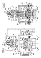
- the tilting clamp 200 illustrated in FIGS. 5 to 7 is essentially constituted by a stirrup 203 suspended from the common connecting chain 12, and a jaw system 210 mounted on said stirrup so as to be able to tilt around an essentially horizontal axis 216, first cam means 16 being further provided, upstream and downstream of the tunnel oven, for pivoting said jaw system by an angle substantially equal to 90 °, and second cam means 15 being also provided for actuating said jaw system.
- the tilting clamp 200 is not directly suspended from the common connecting chain 12, but comprises a carriage 201 rolling by means of rollers 202 on a fixed slide 13 defining the raceway of the tilting clamps 200.
- the slide 13 is carried by an upper cover 14 connected to the fixed structure of the device: in this way, the weight of the tilting clamp 200 and the object it carries is supported by the slide 13, no vertical force being thus transmitted to the link chain 12, the sole function of which is to connect the succession of tilting clamps 200 along the raceway.
- the tilting clamps 200 comprise a central actuating rod 205 slidably mounted in a support 204 integral with the stirrup 203.
- the upper end of the actuating rod 205 is connected to a lever 206 mounted oscillating on the carriage 201, said lever carrying a roller 207 which can cooperate with a fixed cam 15 used for actuating the rod 205, for the purpose of opening the clamping jaws 210.
- the lower end of the rod 205 thus constitutes an actuating pusher capable of cooperate with a member 209 connected to the clamping jaws 210.
- a return spring 213 here ensures the ascent of the actuating rod 205, with a view to good contact with the fixed cam 15, when that -this cooperates with the roller 207.
- the member 209 slides telescopically in a body 223 secured to elements 215 supporting the clamping jaws 210.
- a flange 224 provides the connection between the member 209 and the jaws 210 by means of links 212 , arranged above the axes 211 of pivoting of said jaws.
- Each of the clamping jaws 210 thus pivots about an axis 211 carried by the associated element 215, to which an axis 216 is coupled by means of a pin 217.
- the axis 216 is essentially horizontal, and constitutes the tilting axis of the jaw system 210.
- the axis 216 of the jaw system 210 is extended, on one side of the stirrup 203, by a lever 218 carrying a roller 219; the roller lever can cooperate with a fixed outer cam 16 used to control the tilting of the jaw system 210.
- the axis 216 is extended by a lever 220 subjected to the action a spring with protrusion from hard point 221, the other end of which is integral with a pin 222 projecting from the stirrup 203, so as to have two stable angular orthogonal positions: one of these positions, illustrated in solid line in Figure 6, corresponds to a position for gripping or releasing objects for the jaw system 210; the other position, illustrated in dashed lines in FIG. 6, corresponds to a tilted position, in which the gripped object is conveyed in an essentially horizontal position. Note also the presence of a spring 214, ensuring the return of the jaws 210 in the clamping position.
- the roller 219 initiates the rotation of axis 216, and, beyond the hard point of spring 221, there is a tilt to the other stable position, in which the object is then supported in a horizontal position.
- the tilting clamp and the object it supports thus remain in this position during the crossing of the tunnel furnace 100, with a view to the retraction of the heat-shrinkable sleeve on the object, after which the tilting clamp meets another fixed cam 16 provided downstream of the tunnel oven 100, which cam controls the reverse tilting of the system, which brings the object back to its initial vertical position.
- FIGS 1 to 3 also make it possible to distinguish other equipment of the device.
- motor-reduction means 20 are distinguished ensuring the drive of the continuous chain of gripping members 3, said means being mounted on a structure 21.
- Line 23 symbolically recalls the functional connection between means 20 and 22, ensuring synchronization between the respective drive of the continuous chain of gripping members 3 and of conveyor 4, so that the objects 1 appear suitably compared to the associated pliers.
- FIG. 3 makes it possible to distinguish the end 25 of the element supporting the structure 14, and therefore the gripping members 3 via their associated carriage: it is advantageous to be able to adjust in height the continuous chain of gripping, which is here provided in a particularly simple manner thanks to the presence of two columns 26, the lower end of which is in the form of a rack cooperating with an associated actuating pinion 27.
- a thermal protection vault of the mechanical means between the side walls 102 of the tunnel oven 100 arranged here in the form of a vault 105 of trapezoidal section.
- a thermal protection cover 106 is also provided, in order to close the enclosure of the tunnel oven 100 below, this allows the passage to remind that there is no conveyor in the lower part of the tunnel oven, unlike known devices.
- the arch 105 and the cowling 106 thus make it possible to isolate a well-defined enclosure, through which the gripping members 3 supporting the objects pass with their sleeve to be shrunk. Note also the presence here of a cover 17 associated with the return strand of the continuous chain of gripping members.
- blowing means are also used, these means being here integrated into the gripping means, in order to inject air between the object and the sleeve before the latter shrinks.
- a gaseous fluid is blown between the object 1 and the sleeve 2 to be shrunk, and this in a direction essentially parallel to the conveying direction, to inflate the sleeve 2 and keep it out of contact with the object to be coated, the temperature of said gaseous fluid being preferably chosen to achieve, before the actual shrinkage, a progressive balancing of the temperatures inner and outer faces of said sleeve at the softening threshold of the constituent film.
- Such a variant is especially advantageous in the case of objects of non-cylindrical shape, such as objects of conical shape or the like.
- the blowing of gaseous fluid is carried out by the gripping means 3 themselves, so as to organize a flow licking the object 1 beyond said gripping means.
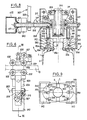
- FIG. 8 thus illustrate such blowing means 350 which are in this case integrated into the gripping members 3 of the objects.
- a tilting clamp 300 is thus distinguished, the jaws 310 of which constitute gaseous fluid blowing members. Only the lower part of the tilting clamp is distinguished here, which comprises a large number of members identical to those of the tilting clamp 200 previously described: therefore identical or homologous members will simply be given the same references increased by one hundred , and will therefore not be described again.
- the essential difference compared to the tilting clamp described above lies in the structure of the tilting pins 316 and the clamping jaws 310.
- the pins 316 are in fact here hollow, and communicate, by a section of flexible tube 351, with a bore central 352 of the associated clamping jaw 310.
- This bore 352 communicates with a transverse recess 353, from which a number of blowing conduits 354 emerge.
- the top view of FIG. 9 thus makes it possible to distinguish a set of five blowing conduits 354, the arrangement of which makes it possible to organize an extremely favorable blowing, since it is carried out very close to the upper surface of the object, which makes it possible to achieve a very favorable bloating effect before the actual shrinkage of the sleeve occurs.
- the means for supplying the gaseous fluid are here produced in the form of a fixed blowing box 400, into which one end of the axis 316 penetrates, through a slot 401 of said box which is closed, on either side from the end of the axis 316, by a flexible double flap 402 (this assembly recalls that conventionally used for cylinders without rod).
Landscapes
- Engineering & Computer Science (AREA)
- Manufacturing & Machinery (AREA)
- Mechanical Engineering (AREA)
- Auxiliary Devices For And Details Of Packaging Control (AREA)
- Shaping By String And By Release Of Stress In Plastics And The Like (AREA)
Applications Claiming Priority (2)
| Application Number | Priority Date | Filing Date | Title |
|---|---|---|---|
| FR8906181A FR2646804B3 (fr) | 1989-05-11 | 1989-05-11 | Procede pour appliquer, par retraction, un manchon thermoretractable sur un objet a revetir, et appareil pour la mise en oeuvre du procede |
| FR8906181 | 1989-05-11 |
Publications (1)
| Publication Number | Publication Date |
|---|---|
| EP0397580A1 true EP0397580A1 (de) | 1990-11-14 |
Family
ID=9381575
Family Applications (1)
| Application Number | Title | Priority Date | Filing Date |
|---|---|---|---|
| EP90401263A Ceased EP0397580A1 (de) | 1989-05-11 | 1990-05-11 | Verfahren, um eine thermisch schrumpfbare Muffe auf einen zu beschichtenden Artikel aufzuschrumpfen und Apparat zu dessen Durchführung |
Country Status (3)
| Country | Link |
|---|---|
| EP (1) | EP0397580A1 (de) |
| CA (1) | CA2016263A1 (de) |
| FR (1) | FR2646804B3 (de) |
Cited By (3)
| Publication number | Priority date | Publication date | Assignee | Title |
|---|---|---|---|---|
| EP0549121A2 (de) * | 1991-11-19 | 1993-06-30 | McNEIL-PPC, INC. | Vorrichtung zum Aufbringen einer wärmeschrumpfbaren Hülse auf einen Behälter |
| ES2322751A1 (es) * | 2009-02-16 | 2009-06-25 | Etiquetas Y Graficas Del Vinalopo S.L. | Maquina para aplicacion en un recubrimiento de plastico sobre un palo de fregona, cepillo o similar. |
| EP2128029A1 (de) * | 2008-05-28 | 2009-12-02 | Ferag AG | Vorrichtung und Verfahren zum Verpacken von flachen Gegenständen |
Families Citing this family (1)
| Publication number | Priority date | Publication date | Assignee | Title |
|---|---|---|---|---|
| CN111674029B (zh) * | 2020-06-30 | 2021-12-14 | 烟台三环锁业集团浦江有限公司 | 锁具薄膜包覆装置及其包覆方法 |
Citations (2)
| Publication number | Priority date | Publication date | Assignee | Title |
|---|---|---|---|---|
| DE2610051A1 (de) * | 1976-03-11 | 1977-09-15 | Owens Illinois Inc | Verbessertes verfahren und vorrichtung zur erzeugung von behaeltern mit einer plastikabdeckung |
| FR2346129A1 (fr) * | 1976-03-31 | 1977-10-28 | Owens Illinois Inc | Procede pour la retraction par chauffage de manchons d'emballage thermoplastiques sur des recipients en verre |
-
1989
- 1989-05-11 FR FR8906181A patent/FR2646804B3/fr not_active Expired - Lifetime
-
1990
- 1990-05-08 CA CA 2016263 patent/CA2016263A1/fr not_active Abandoned
- 1990-05-11 EP EP90401263A patent/EP0397580A1/de not_active Ceased
Patent Citations (2)
| Publication number | Priority date | Publication date | Assignee | Title |
|---|---|---|---|---|
| DE2610051A1 (de) * | 1976-03-11 | 1977-09-15 | Owens Illinois Inc | Verbessertes verfahren und vorrichtung zur erzeugung von behaeltern mit einer plastikabdeckung |
| FR2346129A1 (fr) * | 1976-03-31 | 1977-10-28 | Owens Illinois Inc | Procede pour la retraction par chauffage de manchons d'emballage thermoplastiques sur des recipients en verre |
Cited By (7)
| Publication number | Priority date | Publication date | Assignee | Title |
|---|---|---|---|---|
| EP0549121A2 (de) * | 1991-11-19 | 1993-06-30 | McNEIL-PPC, INC. | Vorrichtung zum Aufbringen einer wärmeschrumpfbaren Hülse auf einen Behälter |
| EP0549121A3 (en) * | 1991-11-19 | 1993-08-18 | Mcneil-Ppc, Inc. | System for applying a heat shrinkable sleeve to a container |
| US5390477A (en) * | 1991-11-19 | 1995-02-21 | Mcneilab, Inc. | System for applying a heat shrinkable sleeve to a container |
| US5475969A (en) * | 1991-11-19 | 1995-12-19 | Mcneil-Ppc, Inc. | System for applying a heat-shrinkable sleeve to a container |
| US5628847A (en) * | 1991-11-19 | 1997-05-13 | Mcneil-Ppc, Inc. | System for applying a heat-shrinkable sleeve to a container |
| EP2128029A1 (de) * | 2008-05-28 | 2009-12-02 | Ferag AG | Vorrichtung und Verfahren zum Verpacken von flachen Gegenständen |
| ES2322751A1 (es) * | 2009-02-16 | 2009-06-25 | Etiquetas Y Graficas Del Vinalopo S.L. | Maquina para aplicacion en un recubrimiento de plastico sobre un palo de fregona, cepillo o similar. |
Also Published As
| Publication number | Publication date |
|---|---|
| FR2646804B3 (fr) | 1991-09-13 |
| CA2016263A1 (fr) | 1990-11-11 |
| FR2646804A1 (fr) | 1990-11-16 |
Similar Documents
| Publication | Publication Date | Title |
|---|---|---|
| EP0527091B1 (de) | Verfahren und Vorrichtung für die Umverpackung von Gepäck von Benutzern verschiedener Transportmittel | |
| EP1951577B1 (de) | Verfahren und maschine zur herstellung und anordnung einer dehnfolienverpackungshülle auf einer palettierten last | |
| EP1188676A1 (de) | Satz von Zuschnitten, Verfahren und Vorrichtung zum Verpacken eines Produktes oder einer Menge Artikeln nichtspezifischer Form | |
| FR2630995A1 (fr) | Procede et appareil pour appliquer sur des conteneurs des etiquettes d'enveloppement circonferentielles | |
| FR2484365A1 (fr) | Procede et appareil pour appliquer des manchons en matiere plastique sur des recipients | |
| EP0351308A1 (de) | Verfahren zur Temperaturregelung eines beidseitig offenen Tunnelofens und Einrichtung zu dessen Durchführung | |
| CH448865A (fr) | Procédé d'emballage et machine pour sa mise en oeuvre | |
| EP0397579A1 (de) | Verfahren zum Kontrollieren der Temperatur eines an beiden Enden offenen Tunnelofens und dazugehörige Vorrichtung | |
| EP0000851B1 (de) | Automatische Vorrichtung zum Zerteilen eines thermoplastischen Schlauches und zum Überziehen von Behältern mittels dieser Schlauchteilen | |
| CA1074070A (fr) | Apparreillage de pose de troncons de gaine thermoplastique autour de recipients | |
| CA2286383A1 (fr) | Procede et dispositif pour thermoretracter une gaine en matiere synthetique sur une bouteille de gaz et bouteille obtenue | |
| EP0397580A1 (de) | Verfahren, um eine thermisch schrumpfbare Muffe auf einen zu beschichtenden Artikel aufzuschrumpfen und Apparat zu dessen Durchführung | |
| EP0389315B1 (de) | Positionierung einer Glasscheibe gegenüber Vorrichtungen zum Biegen und/oder für andere thermische Behandlungen | |
| EP0069011B1 (de) | Vorrichtung zum Anbringen und Zentrieren eines thermoplastischen Schlauches um Gegenstände durch ein vertikales mit schwebenden Dorn versehenes Element | |
| FR2613703A1 (fr) | Convoyeur a plaques permettant notamment le transport de recipients | |
| FR2588828A1 (fr) | Procede et appareil pour l'application, par retraction, d'un troncon de gaine thermoretractable autour d'objets a revetir | |
| CA2182307A1 (fr) | Manipulation de pneumatiques vulcanises, en particulier refroidissement de ceux-ci | |
| CA1259049A (fr) | Machine de pose de manchons autour d'objets poses a plat | |
| FR2459176A1 (fr) | Procede et appareil pour monter des manchons tubulaires preformes sur des recipients places en alignement precis | |
| EP2429798A1 (de) | Verfahren und vorrichtung zum warmfomen und verzieren von behältern | |
| FR2490590A1 (fr) | Dispositif pour machine d'ouverture, transfert de decoupe de gaine thermoplastique en manchons pour pose autour de recipients | |
| FR2463726A1 (fr) | Procede et machine pour la retraction d'une housse en matiere plastique recouvrant une charge palettisee | |
| FR2948922A1 (fr) | Installation d'emballage comprenant au moins deux modules distincts dont un au moins est mobile par rapport a une direction de convoyage des produits a emballer | |
| EP0059674A1 (de) | Siebdruckvorrichtung für Flakons oder dgl. | |
| CA2453011C (fr) | Procede et installation de pose de manchons etirables |
Legal Events
| Date | Code | Title | Description |
|---|---|---|---|
| PUAI | Public reference made under article 153(3) epc to a published international application that has entered the european phase |
Free format text: ORIGINAL CODE: 0009012 |
|
| AK | Designated contracting states |
Kind code of ref document: A1 Designated state(s): AT BE CH DE DK ES FR GB GR IT LI LU NL SE |
|
| 17P | Request for examination filed |
Effective date: 19910506 |
|
| 17Q | First examination report despatched |
Effective date: 19921127 |
|
| STAA | Information on the status of an ep patent application or granted ep patent |
Free format text: STATUS: THE APPLICATION HAS BEEN REFUSED |
|
| 18R | Application refused |
Effective date: 19930517 |