EP0397472A2 - Verfahren und Aufzeichnungs- und Wiedergabegerät mit einem rotierenden Kopf - Google Patents
Verfahren und Aufzeichnungs- und Wiedergabegerät mit einem rotierenden Kopf Download PDFInfo
- Publication number
- EP0397472A2 EP0397472A2 EP90304995A EP90304995A EP0397472A2 EP 0397472 A2 EP0397472 A2 EP 0397472A2 EP 90304995 A EP90304995 A EP 90304995A EP 90304995 A EP90304995 A EP 90304995A EP 0397472 A2 EP0397472 A2 EP 0397472A2
- Authority
- EP
- European Patent Office
- Prior art keywords
- tracks
- digital information
- samples
- regions
- information signals
- Prior art date
- Legal status (The legal status is an assumption and is not a legal conclusion. Google has not performed a legal analysis and makes no representation as to the accuracy of the status listed.)
- Granted
Links
Images


Classifications
-
- G—PHYSICS
- G11—INFORMATION STORAGE
- G11B—INFORMATION STORAGE BASED ON RELATIVE MOVEMENT BETWEEN RECORD CARRIER AND TRANSDUCER
- G11B20/00—Signal processing not specific to the method of recording or reproducing; Circuits therefor
- G11B20/10—Digital recording or reproducing
- G11B20/10527—Audio or video recording; Data buffering arrangements
-
- G—PHYSICS
- G11—INFORMATION STORAGE
- G11B—INFORMATION STORAGE BASED ON RELATIVE MOVEMENT BETWEEN RECORD CARRIER AND TRANSDUCER
- G11B20/00—Signal processing not specific to the method of recording or reproducing; Circuits therefor
- G11B20/10—Digital recording or reproducing
- G11B20/18—Error detection or correction; Testing, e.g. of drop-outs
- G11B20/1806—Pulse code modulation systems for audio signals
- G11B20/1809—Pulse code modulation systems for audio signals by interleaving
Definitions
- the present invention relates to apparatus with a rotary head for recording and playing back digital audio signals or other digital information signals.
- VTRs Video-tape recorders with a rotary head for recording high definition television signals (hereinafter referred to as HDTV signals), by forming helical tracks on a magnetic tape, and playing back the recorded signals have been developed.
- HDTV signals high definition television signals
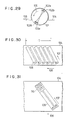
- a magnetic tape 104 moving in the direction of an arrow 106 is passed around a rotary drum 101 rotating in the direction indicated by an arrow 105.
- a pair of heads 102a and 102b are disposed adjacent to each other and serve for channels A and B (hereinafter referred to as CH.A and CH.B), and another pair of heads 103a and 103b adjacent to each other are disposed 180° spaced apart from the heads 102a and 102b to serve for a pair of channels.
- the magnetic heads mounted on the periphery of the rotary drum 101 scan the magnetic tape 104 in the direction indicated by an arrow 107 (Fig. 30). During recording, such scanning form tracks 108, each of which is formed by one scanning by a head for one channel.
- a video signal of one field is recorded over an area T which comprises several tracks.
- a pair of tracks CH.A and CH.B formed by the pair of heads are called a segment.
- a video signal of one field is therefore recorded in three segments.
- the VTR recording HDTV signals records signals of a frequency band wider than the conventional TV signals. The following methods are therefore employed.
- a scheme widely adopted in recording and playing back the HDTV signals is to divide the video signal of one field or one frame into a plurality of segments each consisting of a plurality of channels.
- VTRs described above when a digital audio signal is to be recorded in addition to the video, for the purpose of facilitating independent rewriting of the video and the audio (after-recording), it is contemplated to dispose a region for digital audio recording on the extension of the video tracks, as in an 8 mm VTR.
- Fig. 31 is a schematic diagram showing the track patterns recorded by such a device.
- a video signal of one field is divided into 2. channels, A and B, and recorded in a single segment.
- the signal area for the video signal on one track is denoted by 109.
- the audio signal of the two channels in the one field is recorded in the digital audio signal areas 110 formed in each track, being separated from the video signal areas by a gap of a predetermined length.
- the audio signal of one channel is recorded in association with the area for the video signal for one channel, CH.A, and the audio signal of the other channel is recorded in association with the area for the video signal of the other channel, CH.B.
- Another problem is that the recording system does not have sufficient error correcting or error compensating capability against burst errors due to an extended scratch on the tape.
- An object of the invention is to provide a rotary head digital signal recording and playback apparatus having a capability of correcting and compensating the loss of signals throughout one complete track or the burst errors due for example to an extended scratch on the tape.
- a rotary-head recording/playback apparatus digital signals of a plurality of channels are recorded, being distributed in m x n tracks (m and n being an integer equal to or greater than 2), digital signals for each channel in a unit time are divided into m x n sample groups, i.e., (m x n x 1)-th to ⁇ (m x n x 1) + (m x n -1) ⁇ -th sample groups according to the order of input or sample, and disposed so that each track contains only one of the (m x n) sample groups and the sample groups containing adjacent samples of the same channel are disposed being spaced in the longitudinal direction of the tracks.
- At least part of the error correcting codeword is formed to interleave a plurality of tracks of the m x n tracks (in other words, to extend across such a plurality of tracks), and the same error correcting codeword does not contain adjacent samples.
- the digital audio signals of one field or one frame are divided into (2 x j) sample groups so that the even-numbered samples and odd-numbered samples belong to different groups, and one even sample group and one odd sample group are selected out of the (2 x j) sample groups so that the sample groups are divided into j groups
- the sample groups containing adjacent samples in the same channel are disposed in regions spaced apart from each other in the longitudinal direction of the tracks, and the error correcting codeword for the digital audio signals contained in each track are formed to be completed across a plurality of tracks and adjacent samples in the same channel are contained in different error-correcting codewords.
- any arbitrary sample data and sample data adjacent thereto are recorded on different tracks, being spaced apart from each other in the longitudinal direction of the tracks.
- the error correction is made using the error-correcting code that is recorded being distributed on different tracks.
- the error correcting capability against burst errors within a track can be improved. Where a burst error which is beyond the error correcting capability occurs, at least one of the adjacent data can be corrected without being affected by the burst error, and a correct sample is obtained, and also an adequate compensating capability is obtained.
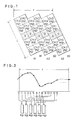
- audio information signals are recorded and played back in four channels: channel 1, channel 2, channel 3, and channel 4.
- the three even groups eg1 to eg3 comprise all the even-numbered samples in each field, and three odd groups og1 to og3 comprise all the odd-numbered samples.
- the areas marked Q in Fig. 1 contain check symbols (error check redundant symbols) for detecting and correcting errors in the PCM audio sample values.
- the check symbols (P) are also contained in the areas for the audio data symbols, marked CH.1eg1, CH.2eg1, etc. being distributed among the audio data symbols.
- the interleaving rule in Fig. 1 is that a single track contains only one of the m x n sample groups for each audio channel, and adjacent sample groups in each channel are separated from each other in the longitudinal direction of the tracks, i.e., they are disposed in differently-numbered regions in different tracks.
- the rule ensures that, in each channel, samples that are consecutive or adjacent in time are disposed in different tracks in locations separated by at least one-half the audio track length (L) measured in the direction in which the tracks are scanned.
- the reason for locating the area marked Q, which contains part of the check symbols, in the middle is that adjacent samples will bc separated by the additional length of the Q area, thus enhancing the interleaving effect of the invention.
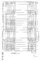
- Fig. 4 shows the structure of error-correcting code comprising the PCM audio data symbols and check symbols for one field f as it would be stored in a signal memory device used in the recording and playback apparatus.
- the memory can be written and read eight bits (one byte) at a time.
- the sixteen-bit audio sample values are divided into eight upper bits and eight lower bits, each eight bits being stored in a one-byte slot.
- the eight-bit data in a slot is referred to as a symbol.
- the signal data structure in one plane in Fig. 4 corresponds to the PCM audio data symbols arid check symbols for one track.
- the planes A1 to A3 and B1 to B3 correspond to the tracks A1 to A3 and B1 to B3 in Fig. 1.
- Each audio data symbol is denoted by the capital letter D followed by a suffix indicating its sample number and whether it is the upper (u) or lower (l) byte of the sample.
- the 0-th sample in each channel comprises two symbols denoted D0u and D01.
- Pxx denotes a check symbol (P symbol) belonging to a first or vertical error-correcting code.
- Qxx denotes a check symbol (Q symbol) belonging to a second or horizontal error-correcting code.
- Each of the vertical error-correcting codewords in Fig. 4 consists of 38 symbols, comprising 34 audio data symbols or Q symbols and four P symbols.
- the 38 symbols in a vertical error-correcting codeword are treated as a data block. Blocks are read from memory and written on the tape in the order of the block addresses shown in Fig. 4, thus permuting or interleaving the data as illustrated in Fig. 1.
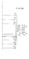
- Fig. 2 shows the arrangement of data on a track of the tape.
- each region e.g., CH.1eg1 contains 8 blocks
- each block contains 34 audio data symbols and 4 check symbols plus synchronous (sync. ) code, block address signal, and a parity code for detecting errors in block address signal.
- the sampled audio data for the four channels are written in the designated slots in the six-track memory area in a recording memory shown in Fig. 4, and are then recorded on the tape sequentially.
- the audio data that are sequentially read from the tape are stored in the designated slots in the six-track memory area in a playback memory and are then read from the specified slots and output in the original sample order.
- RS Reed-Solomon
- the P and Q error-correcting codes comprise four symbols per codeword, enabling the correction of two incorrect symbols of arbitrary location in the error-correcting codeword (referred to as error correction), or up to four incorrect symbols if the locations of the incorrect symbols are known by other means (referred to as erasure correction).
- the general procedure for correcting errors is first to use the P symbols to determine whether there is a symbol error in the vertical error-correcting code and store the result of the decoding of the vertical error-correcting code in a separate flag memory as flag information, then use the Q symbols to perform erasure correction, the positions of the errors being indicated by the flags.
- the horizontal error-correcting codewords can be structured and the Q check symbols generated according to two methods.
- One method is to proceed in the straight horizontal direction in Fig. 4, so that each error-correcting codeword is extend in one plane, that is, within one track.
- An advantage of this method is that an uncorrectable error in one track does not affect other tracks.
- a disadvantage is that burst errors continuing for more than four blocks per track cannot be corrected, but must be replaced by compensation, such as mean value interpolation. This method is accordingly unsuitable for systems prone to burst errors in the longitudinal direction of the tracks.
- the second method is to interleave the error-correcting codewords across two or more segments (i.e., to make the error-correcting codeword to extend across two or more segments), thus enabling longer burst errors to be corrected.
- a disadvantage of this method is that if all the data in a certain track are incorrect, due to head clogging for example, the error will affect other tracks that are part of the same error-correcting code structure, thus increasing the amount of data that must be compensated.
- the error-correcting codes must therefore be structured so that it will not be necessary to compensate the values of adjacent samples.
- Fig. 5 is a schematic view of the A1, A2, and A3 planes (or B1, B2, and B3 planes) in Fig. 4 as seen from above, looking parallel to the planes, showing an embodiment of the structure of a horizontal error-correcting codeword.
- the error-correcting codeword comprises samples from three tracks, one track in each of the three segments making up the field.
- the arrow labeled Qseq in Fig. 5 indicates an error-correcting codeword starting in the plane A1 (or B1), comprising 36 symbols joined by solid and dashed lines, 32 of which are audio data symbols and four of which are Q check symbols.
- the codeword in Fig. 5 does not contain any pair of adjacent samples. If an uncorrectable burst error occurs, such as a burst error comprising 13 consecutive blocks in a track, even though all audio data symbols in the codeword are regarded as incorrect, their adjacent symbols are not affected because they are part of codewords disposed across different tracks, hence the correct adjacent values can be obtained for compensation. Thus adequate compensating capability is assured as well as adequate error-correcting capability.
- Fig. 5 shows only the codword beginning in the A1 (or B1) plane. Similar codewords are generated beginning in the A2 (or B2) and A3 (or B3) planes.
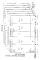
- Fig. 6 is a block diagram showing the configuration of a VTR for an HDTV signal according to this embodiment.
- Fig. 7 is a diagram showing the timing of the recording and playback of a PCM audio signal according to this embodiment.
- 201a to 201d denote analog audio signal input terminals of the four channels
- 202a to 202d denote low-pass filters (LPFs) in the recording circuit of the four channels
- 203a and 203b are selectors for selecting the audio signals, each provided for two channels, and outputting a signal of one circuit.
- 204a and 204b are analog-to-digital converters (A/D converters).
- 205 is a data bus for the memory for the recording circuit.
- 207 is a memory address controller.
- 208 is a coding circuit.
- 209a and 209b are a synchronous signal and block address signal appending circuit (hereinafter referred to as sync. signal appending circuit).
- 210a and 210b denote digital modulators
- 214 is an HDTV video signal processing circuit.
- 215 is a video signal input terminal.
- 216 is a video signal output terminal.
- 211a and 211b are selectors which make selection between the PCM audio recording signal and the video recording signal.
- 212a and 212b are recording amplifiers, 213a and 213b denote recording/playback signal selecting switch.
- 218a and 218b are playback amplifiers, 219a and 219b denote playback equalizers.
- 220a and 220b denote synchronous signal detecting circuits.
- 221a and 221b denote demodulators.
- 222 is a memory data bus for the playback circuit.
- correcting circuit denotes an error detecting and correcting circuit (hereinafter referred to as correcting circuit).
- 225a and 225b denote compensating circuit.
- 226a and 226b denote digital-to-analog converters (D/A converters).
- 227a and 227b denote channel separators.
- 228a to 228b denote low-pass filters (LPFs) for the playback circuit.
- 229a to 229d denote analog output terminals of the four channels.
- 230 denotes a timing generating circuit for generating clocks required by each circuit block.
- 231 denotes a quartz oscillator for generating a master clock.
- Audio signals of the four channel input through the analog audio signal input terminals are passed through the LPFs 202a to 202d where their high frequency components are suppressed, and selected by the selectors 203a and 204b, and are then input into the A/D converters 204a and 204b.
- two A/D converters are provided because the A/D conversion is made after the selection.
- separate A/D converters may be provided for the respective channels.
- the audio signal of each channel is converted into a digital signal of 16 bits.
- the digitized audio signal is then passed through the memory bus 205 of the recording circuit, and written in a recording memory 206.
- the recording memory 206 has three times the capacity for storing the audio data and error correcting codewords of the four channels for one field period.
- the audio data input during one field period (the period IN in the figure) is read during the next field period (the period ENC in the figure), and passed through the data bus 205 to the correcting circuit 208, where error correcting codes P and Q are generated, and the generated error correcting codes P and Q are passed through the data bus 205 and written in the recording memory 206.
- the data written in the recording memory 206 are then divided into three segments, and read, with the time-axis-compressed, to be recorded in the above described audio regions.
- the recording on the tape is made segment by segment, i.e., with two adjacent heads forming simultaneously two adjacent tracks.
- two sets of circuits including the sync. signal appending circuits 209a and 209b, and the circuits that follow them are provided.
- Data read from the recording memory 206 with the time-axis-compressed are supplied to the sync. signal appending circuits 209a and 209b where a block sync. signal, a block address, and a parity code for error detection for the block address signal are appended to the head of each block.
- the data are then modulated at the modulators 210a and 210b.
- the modulation employed is an 8-14 modulation in which 8-bit data are modulated into 14-bit data.
- the video processing circuit 214 converts the HDTV video signal supplied to the video signal input terminal 215 in a recording signal in accordance with a predefined sequence. During playback, the reverse processing is made to output the video signal at the video signal output terminal 216. But as these operations are not relevant to the gist of the invention, so their description is omitted.
- the selectors 211a and 211b select the video signal and the time-axis-compressed audio signal so that they will be recorded in the respective divided regions, and the selected signals are amplified at the recording amplifiers 212a and 212b, passed through the recording switches 213a and 213b and supplied to two pairs of heads 102a and 102b; and 103a and 103b by means of which the signals are recorded on the track pattern on the tape, shown in Fig. 1.
- the playback memory 223 juxtaposed to the area for storing the audio data and error correcting codewords is an area for storing flag information indicating the result of the error detection and the result of correction. In this area, flags corresponding to the audio data on which error has been detected but which could not been corrected.
- the audio data of one field on which correction has been completed are then read from the playback memory 223 with the time axis expanded during the next field period, and input to the compensating circuits 225a and 225b. Flags corresponding to the audio data 223 are also supplied to the compensating circuits 225a and 225b.
- the compensating circuits 225a and 225b identify, by means of flag, the audio data on which error has been detected but which has not been corrected, and perform the compensation processing, and minimize the possibility of such erroneous audio signal being heard as an unpleasant sound.
- the preceding value hold method in which the incorrect values are replaced by the immediately preceding correct value is employed, or whereas when the values of the preceding sample and the succeeding sample are correct, the mean value compensating method in which the incorrect values are replaced by the mean value between them are used in place. The latter method is preferred because the unpleasant sound is smaller.
- the compensated audio data are converted into analog signals at the D/A coverters 226a and 226b, and separated into two channels at the channel separators 227a and 227b, and passed through the LPFs 228a to 228d where the high-frequency components are suppressed.
- the signals are then output through the audio output terminals 229a to 229d.
- the memory address controller 207 provides memory addresses to the recording memory 206 and the playback memory 223 during data writing and data reading.
- the recording circuit and the playback circuit are shown to be separate, but where the recording and playback operation need not be carried out simultaneously, some of the circuit blocks or part thereof may be used to serve both for recording and playback.
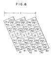
- Fig. 8 is a data arrangement diagram showing the interleaving pattern in this embodiment.
- the allocation of data samples into sample groups is identical to that shown in Fig. 3, but the disposition of the sample groups is different.
- the advantages similar to those derived from the interleaving pattern shown in Fig. 1 is also obtained.
- Apparatus for implement this interleaving can be structured by changing the configuration of the memory and the memory address controller.
- Fig. 9 is a data arrangement diagram showing data interleaving
- Fig. 10 is a schematic diagram showing the allocation of data in one audio channel.
- samples of one channel input or sampled during one field period for each of the channels CH.1, CH.2, CH.3 and CH.4 are divided substantially evenly into 18 groups. If the samples generated per field period are denoted by D0, D1, D2, ..., these samples are divided into sample groups CH.1e1, CH.1o1, CH.1e2, CH.1o2, ...CH.1e9, CH.1o9.
- the suffix e signifies groups consisting of even samples
- suffix o signifies groups consisting of odd samples.
- the sample groups formed for each channel are disposed on tracks as shown in Fig. 9.
- Q denote check symbols.
- a group of even samples and a group of odd samples of each channel are disposed, being spaced, in the former part and a latter part within the audio area in tracks.
- Sample groups containing adjacent samples in each channel are disposed on different tracks, and separated in the longitudinal direction of the tracks, i.e., they are disposed in differently-numbered regions in different tracks.
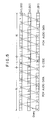
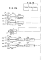
- Fig. 11 is a code structure diagram (like Fig. 4) and Fig. 12 which is an error-correcting codeword diagram (like Fig. 5).
- the number of samples (Nsf) per channel in one field period f is 800.
- each track must have audio data slots for 356 samples or 712 symbols.
- each track is provided with slots for 720 audio data symbols, the unused slots being treated as dummy symbols.
- Each block consists of 34 symbols aligned vertically, and the recording on the tape is in the order of the block addresses shown in Fig. 11, so the symbols are read from the memory, one block at a time, and recorded to realize the interleave pattern shown in Fig. 9.
- the sampled audio data of the 4 channels are written in the memory, being allocated in tlie designated slots in the memory areas for the 9 tracks shown in Fig. 11.
- the audio data are read from the designated slots and the original order is restored and output to the compensating circuit.
- each of the Q error-correcting codewords is completed in three tracks A1, A2 and A3, in the same way as in Fig. 5.
- the data correcting capability and compensating capability as described earlier are also attained.
- FIG. 13 An embodiment of the recording and playback apparatus for implementing the interleaving of the audio samples and code structure as described above will now be described with reference to Fig. 13.
- the apparatus shown in Fig. 13 is similar to the apparatus shown in Fig. 6, but differs in the following respects. That is, there are heads for the three channels, and the circuits for recording and playback for the additional channel is added.
- the recording memory 206 and the playback memory 223 have a different memory configuration corresponding to the different interleaving structure.
- the memory address controller for data writing and data reading also has different configuration.
- the procedure for the recording and playback is identical to that shown in the timing chart of Fig. 7.
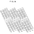
- Fig. 14 shows a further embodiment of data interleaving according to the invention.
- groups containing adjacent samples are disposed in different segments of the same field.
- the video signal for one field is divided into 3 channels x 3 segments.
- the concept described is however applicable to the case where there are 3 channels x 2 segments.
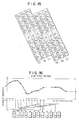
- Fig. 15 shows an interleaving pattern for such a case.
- This example correspond to the division of 3 channels x 2 segments shown in Fig. 15.
- the audio is signals are confined within one field, but audio can be distributed across two fields or one frame.
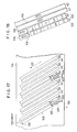
- Fig. 17 shows a track pattern according to another embodiment of the invention.
- each track has a region 110 for recording audio signals, but in this embodiment, every third segment has regions 501 to 504 for audio signals in the form of PCM signals.
- the segments with even suffixes "n" (of An, Bn) are recorded by means of the pair of heads 102a and 102b. Part of the vertical blanking period of the video signal is used for the regions of the PCM signals. Accordingly, the digitized audio signals can be recorded without altering the video format.
- the vertical sync. signal is recorded in the sync. signal region 510 provided at the head of the video signal region 109 following the PCM signal regions 501 to 504.
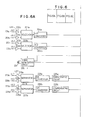
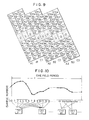
- Fig. 18 shows the recording pattern for recording audio signals of four channels (A, B, C, D), and is an enlarged view of the regions 501 and 502 of Fig. 17.
- the audio signals for each channel sampled in one video field are divided into a group of even samples and a group of odd samples, which are then recorded in the former part and a latter part of the area for the audio on different tracks.
- the suffixes "e” and "o" of the reference marks A, B, C, D signify the even sample and odd samples.
- the symbols Q are check symbols of the error correction code completed in one track.
- the preceding and succeeding samples are unaffected, so the dropped sample can be replaced by a mean value of the preceding and succeeding samples, i.e., by interpolation. If a burst error which extends one half the area for the audio, i.e., the regions 501 and 502 in the direction of the width of the tape occurs, the interpolation is possible.
- Fig. 19 shows the timing for recording and playback of audio signals in this embodiment, and corresponds to Fig. 7.
- the method shown in Fig. 19 differs from the method shown in Fig. 7 in that the signals in one field is recorded on the tape, being concentrated at the beginning of each field.
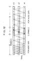
- Fig. 20 is a memory map for the above embodiment.
- the audio signal sampling rate is 48kHz
- the number of samples (Nsf) per channel in one filed is 800.
- each track must have audio data slots for 1600 samples or 3200 symbols.
- each of the four audio regions has data slots for 924 symbols, 44 symbols in each vertical array, and 21 symbols in each horizontal array.
- the signals of Ach, Bch, Cch, and Dch are respectively stored at the locations with the x address of 0 to 20, 21 to 41, 54 to 74, and 75 to 95.
- Q denotes check symbols of the horizontal error-correcting code and stored in the region of the x addresses of 42 to 53.
- P denotes check symbols of the vertical error-correcting code.
- the first suffix denotes the order of the sample and the second suffix denotes whether it is an upper (u) or lower (1) byte of the sample.
- the audio signals input in one field period are stored in the recording memory 206, before being recorded in the audio regions 501 in the A1 track, and the audio region 502 in the B1 track.
- each data symbol belongs two error-correcting codewords, and the data syinbols are coded, taking each byte as a unit, by means for example of the Reed Solomon code which is often employed for error correction of audio signals.
- Each of P error-correcting codewords is formed of 44 symbols aligned vertically.
- B1 track memory map can be obtained by substituting the even samples Ce of the Cch channel for the even samples Ae of the Ach channel, substituting the even samples De of the Dch channel for the even samples Be of the Bch channel, odd samples Ao of the Ach channel for the odd sample Co of the Cch channel, and odd samples of the Bch channel for the odd samples Do of the Dch channel, and the pattern of Fig. 18 can then be obtained by a similar procedure.
- “id” in the figure denote additional information indicating the sample frequency, presence or absence of the emphasis, the number of the channels, the number of quantization bits, or the like, related to the audio signal.
- the control over writing and reading is conducted by the memory control circuit 207.
- the even samples Ce and odd samples Co of the C channel, and the even samples De and the odd samples Do of the D channels may be interchanged.
- an identification signal, other than the vertical sync. signal, with which the start of the video signal of each field can be identified may be recorded in the vertical sync. signal region 510.
- each segment consists of two tracks, but each segment may alternatively consist of three tracks.
- three heads proximate to each other are used for recording and playback.
- Fig. 21 shows a track pattern of this embodiment. Recording in audio regions (such as those 601a, 601b, and 601c or 602a, 602b, and 602c) in adjacent tracks is made substantially simultaneously using three heads.
- Fig. 22 shows arrangement of data on the audio regions 601a to 601c.
- the area preceding the area for the check symbols of the Q error correction codeword (Q check symbols) and the area succeeding the area for the Q check symbols are respectively divided into four regions, and allocated to four audio channels A, B, C and D, and the even samples and the odd samples of each audio channel are divided into three, and allocated to three tracks.
- the even samples of the A channel are represented by Ae1, Ae2, Ae3.
- Fig. 23 shows a modification of Fig. 22.
- the even samples and the odd samples obtained by dividing each channel into three are disposed being separated in the longitudinal direction of the tracks so that they are not juxtaposed, i.e., they are in the differently-numbered regions of the different tracks.
- interleaving was confined within one field period, but it may spreads across two field periods or one frame period.
- the tracks 601a to 601c are in a field different from the field in which the tracks 602a to 602c are in. That is, in the interleaving completed in two fields, the audio data generated in two field periods are divded into even groups and odd groups, which are then distributed in the audio regions in two fields.
- Fig. 24 An example of such an arrangement is shown in Fig. 24. In this example, the number of samples in each region is about twice that of the embodiment of Fig. 23.
- the embodiment described above can be implemented by changing the clock generating circuit 230 and the memory control circuit 207.
- Fig. 25 is a modification of the embodiment of Fig. 18. In this modification, the interleaving is made across two fields.
- Fig. 26 is a schematic diagram of the memory configuration of this embodiment.
- each track must have audio data slots for 1600 samples or 3200 symbols.
- a memory is shown to have 8 audio regions for about 1600 symbols, each audio region having 32 symbols in each vertical array and 50 symbols in each horizontal array. The even samples and odd samples of the audio data of one frame are stored being separated. Then, check symbols are generated from the fifty symbols in the Ae region and Co region, and stored in the Qo region. Similarly, check symbols for x direction are also generated for other samples.
- the audio data with the check symbols being appended are read one block at a time, each block consisting of 36 symbols, and blocks stored at the x addresses 0 to 111 are recorded on the A1 track. Similarly, data are read from the memory and recorded on the audio regions in B1 track, A4 track, B4 track. In this way, the recording pattern of Fig. 25 is obtained.
- the control over the writing and recording is made by the memory control circuit 207.
- Fig. 27A and Fig. 27B show track patterns in further embodiments of the invention. They are modifications of Fig. 25.
- the difference of Fig. 27A from Fig. 25 is that Ao and Bo are interchanged.
- the difference of Fig. 27B from Fig. 25 is that Co and Ce; and Do and De are interchanged.
- the track patterns shown in Fig. 27A and Fig. 27B can be realized by changing the order of reading from the memory, which is determined by the memory control circuit 207.
- the audio data comprise 4 channels, but the audio data may comprise two channels.
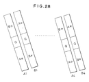
- An example is shown in Fig. 28.
- the audio data of two channels are written in duplicate (i.e., the same audio data are written at two locations), and the even samples and the odd samples of each channel are written in different tracks and at the former part and the latter part. Accordingly, even if drop-out of the signal occurs over one track, or over in half the area in the direction of the width of the tape, no compensation need be made but the correct audio data can be reproduced.
- the track pattern of this embodiment can also be realized by changing the order of the reading from the memory.
- the data generated in one frame are recorded in 2 segments, but by recording a flag indicating the number of recorded samples audio data over a period a shifted from the one frame period of video signal may be recorded as a unit. This modification is useful where the video frame and the audio sampling frequency are not synchronous.
- the embodiments described relate to audio signals, but the invention is also applicable to digital data other than audio digital data.
- the digital information signals are divided according to their order of input or sampling into m x n sample groups, i.e., ⁇ (m x n) x 1 ⁇ -th sample group to ⁇ (m x n) x 1 + (m x n) - 1 ⁇ -th sample group, and one of m x n sample groups is disposed in one track, and the sample groups containing adjacent samples are separated from each other in the longitudinal direction of the tracks, and the error-correcting codeword is formed to interleave across a plurality of tracks in the m x n tracks, and not to contain adjacent samples. Accordingly, compensating capability against head clogging and a burst error due to a scratch is enhanced.
- data interleaving is so made that any arbitrary sample and the sample adjacent thereto are not contained in the same track, and separated from each other in the longitudinal direction of the tracks, and the error-correcting codeword is so formed to interleave across a plurality of tracks, so compensating capability is enhanced.
- the conventional video signal recording format need not be changed, so the compatibility with the conventional apparatus is retained.
Landscapes
- Engineering & Computer Science (AREA)
- Multimedia (AREA)
- Signal Processing (AREA)
- Signal Processing For Digital Recording And Reproducing (AREA)
Applications Claiming Priority (10)
| Application Number | Priority Date | Filing Date | Title |
|---|---|---|---|
| JP119208/89 | 1989-05-12 | ||
| JP11920789 | 1989-05-12 | ||
| JP11920889 | 1989-05-12 | ||
| JP119207/89 | 1989-05-12 | ||
| JP119209/89 | 1989-05-12 | ||
| JP11920989 | 1989-05-12 | ||
| JP27435389 | 1989-10-20 | ||
| JP274353/89 | 1989-10-20 | ||
| JP34143689 | 1989-12-26 | ||
| JP341436/89 | 1989-12-26 |
Publications (3)
| Publication Number | Publication Date |
|---|---|
| EP0397472A2 true EP0397472A2 (de) | 1990-11-14 |
| EP0397472A3 EP0397472A3 (de) | 1991-01-16 |
| EP0397472B1 EP0397472B1 (de) | 1995-11-29 |
Family
ID=27526827
Family Applications (1)
| Application Number | Title | Priority Date | Filing Date |
|---|---|---|---|
| EP90304995A Expired - Lifetime EP0397472B1 (de) | 1989-05-12 | 1990-05-09 | Verfahren und Aufzeichnungs- und Wiedergabegerät mit einem rotierenden Kopf |
Country Status (4)
| Country | Link |
|---|---|
| US (1) | US5491590A (de) |
| EP (1) | EP0397472B1 (de) |
| JP (1) | JP2902049B2 (de) |
| DE (1) | DE69023808T2 (de) |
Cited By (9)
| Publication number | Priority date | Publication date | Assignee | Title |
|---|---|---|---|---|
| EP0464698A1 (de) * | 1990-06-29 | 1992-01-08 | Matsushita Electric Industrial Co., Ltd. | Verfahren zur Aufzeichnung digitaler Signale |
| EP0476630A3 (en) * | 1990-09-18 | 1993-03-17 | Matsushita Electric Industrial Co., Ltd | Data rearrangement processing apparatus for digital video signal recording apparatus |
| EP0504779A3 (en) * | 1991-03-17 | 1993-08-11 | Sony Corporation | A data recording and/or reproducing apparatus |
| EP0504849A3 (en) * | 1991-03-18 | 1994-11-23 | Hitachi Ltd | Pcm signal recording system |
| WO1996020474A3 (en) * | 1994-12-23 | 1996-09-19 | Philips Electronics Nv | A method and device for use with helical scan data recording by implementing a reed-solomon product code, a unitary medium comprising such data, and a cassette comprising such medium |
| EP0506103B1 (de) * | 1991-03-28 | 1997-07-23 | Sony Corporation | Methode zur Datenaufzeichnung |
| EP0682343A3 (de) * | 1994-05-12 | 1999-04-14 | Sony Corporation | Digitalsignalaufzeichnungsgerät |
| CN1100318C (zh) * | 1996-02-13 | 2003-01-29 | 日本胜利株式会社 | 螺线式扫描数据记录设备和螺线式扫描数据再现设备 |
| US7376888B2 (en) | 2004-10-19 | 2008-05-20 | International Business Machines Corporation | Interleaved recording of separated error correction encoded information |
Families Citing this family (11)
| Publication number | Priority date | Publication date | Assignee | Title |
|---|---|---|---|---|
| CN1060905C (zh) * | 1993-02-26 | 2001-01-17 | 三星电子株式会社 | 用于盒式磁带录像机音频信号的记录格式、方法及装置 |
| EP0913826A1 (de) * | 1997-10-31 | 1999-05-06 | Hewlett-Packard Company | Kratzschutz in einem Magnetbandspeichersystem |
| JP4505110B2 (ja) * | 2000-06-28 | 2010-07-21 | インターナショナル・ビジネス・マシーンズ・コーポレーション | 磁気テープ記録装置の試験方法および装置 |
| US6978414B2 (en) * | 2001-07-17 | 2005-12-20 | Hewlett-Packard Development Company, L.P. | Method and apparatus for protecting against errors occurring in data storage device buffers |
| US6958873B2 (en) * | 2001-07-31 | 2005-10-25 | Hewlett-Packard Development Company, L.P. | Data rewrite control in data transfer and storage apparatus |
| US6883122B2 (en) * | 2001-07-31 | 2005-04-19 | Hewlett-Packard Development Company, L.P. | Write pass error detection |
| US7042667B2 (en) * | 2001-07-31 | 2006-05-09 | Hewlett-Packard Development Company, L.P. | Data storage |
| KR100619021B1 (ko) * | 2004-05-24 | 2006-08-31 | 삼성전자주식회사 | 오디오 에러 복원 방법 및 장치 및 그를 적용한 디지털오디오 신호 처리 시스템 |
| US7421640B2 (en) * | 2005-08-17 | 2008-09-02 | International Business Machines Corporation | Method and apparatus for providing error correction capability to longitudinal position data |
| US8111477B2 (en) * | 2008-07-11 | 2012-02-07 | Sony Corporation | Recording medium, recording apparatus, reproducing apparatus, and reproducing method |
| US8675649B2 (en) * | 2008-11-18 | 2014-03-18 | Yamaha Corporation | Audio network system and method of detecting topology in audio signal transmitting system |
Family Cites Families (9)
| Publication number | Priority date | Publication date | Assignee | Title |
|---|---|---|---|---|
| JPH07118159B2 (ja) * | 1982-12-06 | 1995-12-18 | ソニー株式会社 | Pcm信号記録方法 |
| DE3340113A1 (de) * | 1983-11-05 | 1985-05-15 | Robert Bosch Gmbh, 7000 Stuttgart | System zur speicherung digital codierter signale auf magnetband |
| US4675754A (en) * | 1984-02-21 | 1987-06-23 | Mitsubishi Denki Kabushiki Kaisha | Magnetic recorder/reproducer |
| JPH07122966B2 (ja) * | 1984-03-19 | 1995-12-25 | 株式会社日立製作所 | 回転ヘッド型pcmレコーダの記録方法及び再生方法 |
| US4807055A (en) * | 1985-09-11 | 1989-02-21 | Pioneer Electronic Corporation | Multi-speed magnetic recording playback |
| JPH01160289A (ja) * | 1987-12-17 | 1989-06-23 | Sony Corp | ディジタル映像信号の伝送方式 |
| JP2615788B2 (ja) * | 1988-03-29 | 1997-06-04 | ソニー株式会社 | デイジタルオーデイオ信号再生装置 |
| JP3050553B2 (ja) * | 1988-04-08 | 2000-06-12 | ソニー株式会社 | データ再生装置 |
| GB2220521B (en) * | 1988-06-07 | 1993-04-28 | Mitsubishi Electric Corp | Digital signal recording method a digital video tape recorder and a recorded tape |
-
1990
- 1990-05-09 EP EP90304995A patent/EP0397472B1/de not_active Expired - Lifetime
- 1990-05-09 DE DE69023808T patent/DE69023808T2/de not_active Expired - Fee Related
- 1990-05-10 JP JP2121560A patent/JP2902049B2/ja not_active Expired - Lifetime
-
1993
- 1993-03-15 US US08/031,482 patent/US5491590A/en not_active Expired - Fee Related
Cited By (12)
| Publication number | Priority date | Publication date | Assignee | Title |
|---|---|---|---|---|
| EP0464698A1 (de) * | 1990-06-29 | 1992-01-08 | Matsushita Electric Industrial Co., Ltd. | Verfahren zur Aufzeichnung digitaler Signale |
| US5311372A (en) * | 1990-06-29 | 1994-05-10 | Matsushita Electric Industrial Co., Ltd. | Method of recording digital signals in an interleaving array form with enhanced error interpolation |
| EP0476630A3 (en) * | 1990-09-18 | 1993-03-17 | Matsushita Electric Industrial Co., Ltd | Data rearrangement processing apparatus for digital video signal recording apparatus |
| US5289322A (en) * | 1990-09-18 | 1994-02-22 | Matsushita Electric Industrial Co., Ltd. | Data rearrangement processing apparatus for digital video signal recording apparatus |
| EP0504779A3 (en) * | 1991-03-17 | 1993-08-11 | Sony Corporation | A data recording and/or reproducing apparatus |
| EP0504849A3 (en) * | 1991-03-18 | 1994-11-23 | Hitachi Ltd | Pcm signal recording system |
| EP0506103B1 (de) * | 1991-03-28 | 1997-07-23 | Sony Corporation | Methode zur Datenaufzeichnung |
| EP0682343A3 (de) * | 1994-05-12 | 1999-04-14 | Sony Corporation | Digitalsignalaufzeichnungsgerät |
| WO1996020474A3 (en) * | 1994-12-23 | 1996-09-19 | Philips Electronics Nv | A method and device for use with helical scan data recording by implementing a reed-solomon product code, a unitary medium comprising such data, and a cassette comprising such medium |
| US5757808A (en) * | 1994-12-23 | 1998-05-26 | U.S. Philips Corporation | Method and device for use with helical scan data recording by implementing a reed-solomon product code, a unitary medium comprising such data, and a cassette comprising such medium |
| CN1100318C (zh) * | 1996-02-13 | 2003-01-29 | 日本胜利株式会社 | 螺线式扫描数据记录设备和螺线式扫描数据再现设备 |
| US7376888B2 (en) | 2004-10-19 | 2008-05-20 | International Business Machines Corporation | Interleaved recording of separated error correction encoded information |
Also Published As
| Publication number | Publication date |
|---|---|
| US5491590A (en) | 1996-02-13 |
| JP2902049B2 (ja) | 1999-06-07 |
| EP0397472A3 (de) | 1991-01-16 |
| DE69023808D1 (de) | 1996-01-11 |
| JPH03224176A (ja) | 1991-10-03 |
| EP0397472B1 (de) | 1995-11-29 |
| DE69023808T2 (de) | 1996-08-08 |
Similar Documents
| Publication | Publication Date | Title |
|---|---|---|
| US5491590A (en) | Rotary head recording and playback apparatus and method | |
| US5396374A (en) | Method and apparatus for reproducing and after-recording digital information signals on magnetic tape | |
| KR960013768B1 (ko) | 디지탈정보기록방법 | |
| US4541093A (en) | Method and apparatus for error correction | |
| EP0495558B1 (de) | Verfahren und Anordnung zur magnetischen Aufzeichnung und Wiedergabe | |
| US4375100A (en) | Method and apparatus for encoding low redundancy check words from source data | |
| EP0203773B1 (de) | Anordnung zur Dekodierung eines Fehler korrigierenden Codes | |
| US4866636A (en) | Method and apparatus for uniformly encoding data occurring with different word lengths | |
| US4398224A (en) | Time base correcting apparatus | |
| KR850001677B1 (ko) | Pcm신호 기록방법 | |
| US4630272A (en) | Encoding method for error correction | |
| US4685004A (en) | Rotary head type PCM recording and reproduction method and system | |
| EP0222386B1 (de) | Verfahren und Anordnung zur Aufzeichnung und Wiedergabe von PCM-Audiosignalen | |
| US4403261A (en) | Method and apparatus for editing digital signal | |
| US5043830A (en) | System for recording and reproducing digital audio signal | |
| JPS6247375B2 (de) | ||
| US4953168A (en) | Digital signal recording apparatus | |
| US4947271A (en) | Multi-channel recording apparatus | |
| EP0395125A2 (de) | PCM-Aufzeichnungs- und Wiedergabegerät | |
| US5355132A (en) | Method for transmitting digital data | |
| JPH0142069B2 (de) | ||
| US4903148A (en) | Digital signal editing apparatus | |
| JPS6338897B2 (de) | ||
| JPS6244345B2 (de) | ||
| JP2540804B2 (ja) | デジタル信号記録再生装置 |
Legal Events
| Date | Code | Title | Description |
|---|---|---|---|
| PUAI | Public reference made under article 153(3) epc to a published international application that has entered the european phase |
Free format text: ORIGINAL CODE: 0009012 |
|
| AK | Designated contracting states |
Kind code of ref document: A2 Designated state(s): DE FR GB NL |
|
| PUAL | Search report despatched |
Free format text: ORIGINAL CODE: 0009013 |
|
| AK | Designated contracting states |
Kind code of ref document: A3 Designated state(s): DE FR GB NL |
|
| 17P | Request for examination filed |
Effective date: 19901219 |
|
| 17Q | First examination report despatched |
Effective date: 19940505 |
|
| GRAA | (expected) grant |
Free format text: ORIGINAL CODE: 0009210 |
|
| AK | Designated contracting states |
Kind code of ref document: B1 Designated state(s): DE FR GB NL |
|
| REF | Corresponds to: |
Ref document number: 69023808 Country of ref document: DE Date of ref document: 19960111 |
|
| ET | Fr: translation filed | ||
| PLBE | No opposition filed within time limit |
Free format text: ORIGINAL CODE: 0009261 |
|
| STAA | Information on the status of an ep patent application or granted ep patent |
Free format text: STATUS: NO OPPOSITION FILED WITHIN TIME LIMIT |
|
| 26N | No opposition filed | ||
| REG | Reference to a national code |
Ref country code: GB Ref legal event code: 746 Effective date: 19971202 |
|
| REG | Reference to a national code |
Ref country code: FR Ref legal event code: D6 |
|
| REG | Reference to a national code |
Ref country code: GB Ref legal event code: IF02 |
|
| PGFP | Annual fee paid to national office [announced via postgrant information from national office to epo] |
Ref country code: GB Payment date: 20020508 Year of fee payment: 13 Ref country code: FR Payment date: 20020508 Year of fee payment: 13 |
|
| PGFP | Annual fee paid to national office [announced via postgrant information from national office to epo] |
Ref country code: DE Payment date: 20020516 Year of fee payment: 13 |
|
| PGFP | Annual fee paid to national office [announced via postgrant information from national office to epo] |
Ref country code: NL Payment date: 20020529 Year of fee payment: 13 |
|
| PG25 | Lapsed in a contracting state [announced via postgrant information from national office to epo] |
Ref country code: GB Free format text: LAPSE BECAUSE OF NON-PAYMENT OF DUE FEES Effective date: 20030509 |
|
| PG25 | Lapsed in a contracting state [announced via postgrant information from national office to epo] |
Ref country code: NL Free format text: LAPSE BECAUSE OF NON-PAYMENT OF DUE FEES Effective date: 20031201 |
|
| PG25 | Lapsed in a contracting state [announced via postgrant information from national office to epo] |
Ref country code: DE Free format text: LAPSE BECAUSE OF NON-PAYMENT OF DUE FEES Effective date: 20031202 |
|
| GBPC | Gb: european patent ceased through non-payment of renewal fee |
Effective date: 20030509 |
|
| PG25 | Lapsed in a contracting state [announced via postgrant information from national office to epo] |
Ref country code: FR Free format text: LAPSE BECAUSE OF NON-PAYMENT OF DUE FEES Effective date: 20040130 |
|
| NLV4 | Nl: lapsed or anulled due to non-payment of the annual fee |
Effective date: 20031201 |
|
| REG | Reference to a national code |
Ref country code: FR Ref legal event code: ST |