EP0397018B1 - Bremsring-Naben-Verbindung mittels Klemmnuten - Google Patents
Bremsring-Naben-Verbindung mittels Klemmnuten Download PDFInfo
- Publication number
- EP0397018B1 EP0397018B1 EP90108299A EP90108299A EP0397018B1 EP 0397018 B1 EP0397018 B1 EP 0397018B1 EP 90108299 A EP90108299 A EP 90108299A EP 90108299 A EP90108299 A EP 90108299A EP 0397018 B1 EP0397018 B1 EP 0397018B1
- Authority
- EP
- European Patent Office
- Prior art keywords
- hub
- clamping
- section
- cross
- groove
- Prior art date
- Legal status (The legal status is an assumption and is not a legal conclusion. Google has not performed a legal analysis and makes no representation as to the accuracy of the status listed.)
- Expired - Lifetime
Links
Images
Classifications
-
- F—MECHANICAL ENGINEERING; LIGHTING; HEATING; WEAPONS; BLASTING
- F16—ENGINEERING ELEMENTS AND UNITS; GENERAL MEASURES FOR PRODUCING AND MAINTAINING EFFECTIVE FUNCTIONING OF MACHINES OR INSTALLATIONS; THERMAL INSULATION IN GENERAL
- F16D—COUPLINGS FOR TRANSMITTING ROTATION; CLUTCHES; BRAKES
- F16D65/00—Parts or details
- F16D65/02—Braking members; Mounting thereof
- F16D65/12—Discs; Drums for disc brakes
- F16D65/123—Discs; Drums for disc brakes comprising an annular disc secured to a hub member; Discs characterised by means for mounting
-
- B—PERFORMING OPERATIONS; TRANSPORTING
- B61—RAILWAYS
- B61H—BRAKES OR OTHER RETARDING DEVICES SPECIALLY ADAPTED FOR RAIL VEHICLES; ARRANGEMENT OR DISPOSITION THEREOF IN RAIL VEHICLES
- B61H1/00—Applications or arrangements of brakes with a braking member or members co-operating with the periphery of the wheel rim, a drum or the like
-
- F—MECHANICAL ENGINEERING; LIGHTING; HEATING; WEAPONS; BLASTING
- F16—ENGINEERING ELEMENTS AND UNITS; GENERAL MEASURES FOR PRODUCING AND MAINTAINING EFFECTIVE FUNCTIONING OF MACHINES OR INSTALLATIONS; THERMAL INSULATION IN GENERAL
- F16D—COUPLINGS FOR TRANSMITTING ROTATION; CLUTCHES; BRAKES
- F16D65/00—Parts or details
- F16D65/02—Braking members; Mounting thereof
- F16D65/12—Discs; Drums for disc brakes
-
- F—MECHANICAL ENGINEERING; LIGHTING; HEATING; WEAPONS; BLASTING
- F16—ENGINEERING ELEMENTS AND UNITS; GENERAL MEASURES FOR PRODUCING AND MAINTAINING EFFECTIVE FUNCTIONING OF MACHINES OR INSTALLATIONS; THERMAL INSULATION IN GENERAL
- F16D—COUPLINGS FOR TRANSMITTING ROTATION; CLUTCHES; BRAKES
- F16D65/00—Parts or details
- F16D65/02—Braking members; Mounting thereof
- F16D2065/13—Parts or details of discs or drums
- F16D2065/1304—Structure
- F16D2065/1316—Structure radially segmented
-
- F—MECHANICAL ENGINEERING; LIGHTING; HEATING; WEAPONS; BLASTING
- F16—ENGINEERING ELEMENTS AND UNITS; GENERAL MEASURES FOR PRODUCING AND MAINTAINING EFFECTIVE FUNCTIONING OF MACHINES OR INSTALLATIONS; THERMAL INSULATION IN GENERAL
- F16D—COUPLINGS FOR TRANSMITTING ROTATION; CLUTCHES; BRAKES
- F16D65/00—Parts or details
- F16D65/02—Braking members; Mounting thereof
- F16D2065/13—Parts or details of discs or drums
- F16D2065/1304—Structure
- F16D2065/1328—Structure internal cavities, e.g. cooling channels
-
- F—MECHANICAL ENGINEERING; LIGHTING; HEATING; WEAPONS; BLASTING
- F16—ENGINEERING ELEMENTS AND UNITS; GENERAL MEASURES FOR PRODUCING AND MAINTAINING EFFECTIVE FUNCTIONING OF MACHINES OR INSTALLATIONS; THERMAL INSULATION IN GENERAL
- F16D—COUPLINGS FOR TRANSMITTING ROTATION; CLUTCHES; BRAKES
- F16D65/00—Parts or details
- F16D65/02—Braking members; Mounting thereof
- F16D2065/13—Parts or details of discs or drums
- F16D2065/134—Connection
- F16D2065/1356—Connection interlocking
-
- F—MECHANICAL ENGINEERING; LIGHTING; HEATING; WEAPONS; BLASTING
- F16—ENGINEERING ELEMENTS AND UNITS; GENERAL MEASURES FOR PRODUCING AND MAINTAINING EFFECTIVE FUNCTIONING OF MACHINES OR INSTALLATIONS; THERMAL INSULATION IN GENERAL
- F16D—COUPLINGS FOR TRANSMITTING ROTATION; CLUTCHES; BRAKES
- F16D65/00—Parts or details
- F16D65/02—Braking members; Mounting thereof
- F16D2065/13—Parts or details of discs or drums
- F16D2065/134—Connection
- F16D2065/1356—Connection interlocking
- F16D2065/1368—Connection interlocking with relative movement both radially and axially
-
- F—MECHANICAL ENGINEERING; LIGHTING; HEATING; WEAPONS; BLASTING
- F16—ENGINEERING ELEMENTS AND UNITS; GENERAL MEASURES FOR PRODUCING AND MAINTAINING EFFECTIVE FUNCTIONING OF MACHINES OR INSTALLATIONS; THERMAL INSULATION IN GENERAL
- F16D—COUPLINGS FOR TRANSMITTING ROTATION; CLUTCHES; BRAKES
- F16D65/00—Parts or details
- F16D65/02—Braking members; Mounting thereof
- F16D2065/13—Parts or details of discs or drums
- F16D2065/134—Connection
- F16D2065/1392—Connection elements
-
- F—MECHANICAL ENGINEERING; LIGHTING; HEATING; WEAPONS; BLASTING
- F16—ENGINEERING ELEMENTS AND UNITS; GENERAL MEASURES FOR PRODUCING AND MAINTAINING EFFECTIVE FUNCTIONING OF MACHINES OR INSTALLATIONS; THERMAL INSULATION IN GENERAL
- F16D—COUPLINGS FOR TRANSMITTING ROTATION; CLUTCHES; BRAKES
- F16D2250/00—Manufacturing; Assembly
- F16D2250/0038—Surface treatment
- F16D2250/0053—Hardening
-
- F—MECHANICAL ENGINEERING; LIGHTING; HEATING; WEAPONS; BLASTING
- F16—ENGINEERING ELEMENTS AND UNITS; GENERAL MEASURES FOR PRODUCING AND MAINTAINING EFFECTIVE FUNCTIONING OF MACHINES OR INSTALLATIONS; THERMAL INSULATION IN GENERAL
- F16D—COUPLINGS FOR TRANSMITTING ROTATION; CLUTCHES; BRAKES
- F16D65/00—Parts or details
- F16D65/78—Features relating to cooling
Definitions
- the invention relates to a brake ring-hub connection by means of clamping grooves in rail vehicles, wherein the hub carries at least three radially extending clamping grooves between the clamping arms, into which the clamping strips arranged on the brake rings are pressed and the hub is pressed onto the axle shaft.
- the present invention is therefore based on the object of avoiding the known disadvantages of the brake disks previously used and a connection between the brake ring and the hub to create, which can withstand the increased demands of modern traffic and above all can avoid the relatively high loads caused by vertical acceleration.
- the solution to this problem is that the smallest hub cross-section in the clamping groove when the clamping strip is pressed in is larger than the cross-section of the clamping arms in the area with the highest stress requirements and the cross-section of the hub outside the clamping arms is at least partially smaller than the cross-section present in the groove base.
- the base of the groove is advantageously formed by the surface of a half cylinder or by partially straight and tangential areas and / or areas lying concentrically parallel to the hub bore.
- the advantage of the inventive design of the clamping groove is, above all, that the connection of the clamping strip to the clamping groove is maintained even when the brake disk is subjected to very great stress, without the brake ring being able to detach from the hub.
- the clamping arms can be kept considerably shorter and the cross-section of the hub considerably smaller, so that there is a larger friction surface on the brake ring because the brake ring can be kept wider. Nevertheless, the durability of the brake ring-hub connection is considerably better than with the conventional design of the clamp connection.
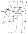
- the drawing shows a side view of a clamping groove 11 designed according to the invention, which is formed by the clamping arms 12.
- the bottom of the groove 13 is formed by a straight and tangentially lying region 14, this region 14 merging with symmetrical circular arcs 15 into the clamping surfaces 16 of the clamping arms 12.
- the cross-section 17 of the hub 18 is smaller than the cross-section 19 lying in the groove base 13.
- This hub cross-section 19 in the groove base 13, which is the smallest cross-section, is larger when the clamping strip 20 is pressed in than the cross-section 21 of the clamping arms 12 in their area which is most highly stressed in terms of strength .
- the base of the groove in the form of a half-cylinder surface and to harden the inner surfaces of the clamping groove 11 evenly and then to temper them at approximately 200.degree.
- the depth of the hardened layer should not be more than 5 mm.
- the hub 18 When using the hub according to the invention for attaching a brake disc to an axle shaft, the hub 18 is first pressed onto the axle shaft 22 which is designed as a hollow tube, the oversize of the shaft 22 being selected such that there is no plastic deformation in any cross section of the hub 18 takes place. However, in order that deformation in the groove 11 is reliably avoided, the cross-section 17 of the hub 18 must be at least partially smaller at individual points than the cross-section 19 present in the groove base 13. After the hub 18 has been applied to the shaft 22, the brake ring with the clamping strips 20 arranged thereon (usually three pieces) can be connected to the hub 18 by pressing the clamping strips 20 into the clamping groove 11.
- the excess of the terminal strips is to be calculated in such a way that the part of the hub 18 lying in the groove base 13 is not permanently deformed. This is achieved in that the smallest cross-section 19 in the clamping groove 11 when the clamping strip 20 is pressed in is larger than the cross-section 21 of the clamping arms 12 in their area which is most highly stressed in terms of strength. This area lies approximately where the straight clamping surfaces 16 end.
- An improvement can be achieved by hardening the inner surfaces in the clamping groove 11 to approximately 52 HRc and tempering at 200 ° C. and not deeper than 5 mm, because residual stresses exist against the operating voltages in the hardened surfaces.
- an area can also be arranged in the groove base 13 without any problem, which region partly consists of a straight region and partly of an region concentrically to the hub bore.
- the straight area can also consist of an area concentric to the hub bore.
- clamping arms 12 can be given other suitable shapes, it only being necessary to ensure that the smallest hub cross-section 19 in the clamping groove 11 when the clamping strip 20 is pressed in is larger than the cross-section 21 of the clamping arms 12 in the area with the highest stress in terms of strength.
Landscapes
- Engineering & Computer Science (AREA)
- General Engineering & Computer Science (AREA)
- Mechanical Engineering (AREA)
- Braking Arrangements (AREA)
Description
- Die Erfindung betrifft eine Bremsring-Naben-Verbindung mittels Klemmnuten bei Schienenfahrzeugen, wobei die Nabe mind. drei radial zwischen Klemmarme sich erstreckende Klemmnuten trägt, in die die an den Bremsringen angeordneten Klemmleisten eingepresst sind und die Nabe auf die Achswelle aufgepresst ist.
- Diese Art der Verbindung von Bremsring und Nabe oder Welle wurde erstmals im DE-PS 1 222 962 vorgeschlagen und hat sich weltweit bewährt, da es einige wesentliche Vorteile besitzt. Dazu gehört vor allem, dass trotz der starken Klemmung der Klemmleisten in der Klemmnut eine radiale Ausdehnung des Bremsrings infolge der Erwärmung beim Bremsen möglich ist, weil die Klemmleiste in der Klemmnut wandern kann, ohne dass gefährliche Spannungen auftreten können, die eine Lösung der Klemmverbindung ergeben.
- Da aber die Beanspruchungen im Eisenbahnverkehr immer grösser wurden, weil die Schienenfahrzeuge auf schlechten Gleisen fahren mussten und/oder höhere Geschwindigkeiten fuhren, wurde die Klemmkraft einerseits und die Ertragbarkeit der Klemmarme andererseits so gross gemacht, dass weder ein Abheben der Klemmleiste auf der in Drehrichtung gesehenen Rückseite erfolgt noch ein plastisches Aufbiegen des im Kontakt mit der Klemmleiste stehennden Klemmarmes der Klemmnut erfolgt. Es kam deshalb zu dem DE-PS 27 42 468, bei dem durch eine bestimmte Form der Klemmnut und Härtung der Klemmnut-Innenfläche ein schneller Verschleiss der Klemmflächen verhindert wird und wobei sich im Breich der Halbzylinder-Bodenfläche der Klemmnut beim Einpressen der Klemmleiste in die Klemmnut Spannungen mit gleichmässigem Verlauf bilden, woraus dann eine grössere Klemmkraft an den Klemmflächen resultiert. Das gehärtete Materialvolumen, welches sich aus der Halbzylinder-Bodenfläche der Klemmnut und der Tiefe der gehärteten Schicht ergibt und Druckeigenspannungen aufweist, dient zur Aufnahme der Bremsbetriebsbeanspruchung, wobei gegen diese Beanspruchung eine grössere Ertragbarkeit der Klemmverbindung gegeben ist als b ei der eingangs genannten Bauweise nach DE-PS 1 222 962.
- Inzwischen haben sich die Beanspruchungen und Anforderungen an Bremsen und Fahrwerk wiederum erheblich gesteigert. Die Klemmverbindungen zwischen Bremsring und Nabe werden zunehmend höher beansprucht. Dabei muss die Klemmkraft einerseits und die Ertragbarkeit der Arme der Klemmverbindung andererseits gegenüber den angreifenden Kräften so gross sein, dass weder ein Abheben der Führungsleiste bzw. Klemmleiste auf der in Drehrichtung gesehenen Rückseite erfolgt, noch ein plastisches Aufbiegen des im Kontakt mit der Führungsleiste bzw. Klemmleiste stehenden Armes der Klemmnut stattfindet. Bei den aus den vorgenannten Beanspruchungen herrührenden Belastungen handelt es sich um Äquivalenzkräfte, die zum Beispiel aus den Vertikalbeschleunigungen resultieren, die auf die Klemmverbindungen einwirken. Ist die Ertragbarkeit der Klemmverbindungen gegenüber diesen Kräften kleiner, so führ dies zum Verlust der Klemmkraft und die Bremsringe lösen sich von der Nabe in Drehrichtung. Wenn damit auch nicht die Sicherheit des Fahrzeugs beim Bremsen verloren geht, weil die Bremsscheibe noch funktionsfähig ist, so muss doch dieser Zustand vermieden werden, damit bei weiterer Benutzung dieser Bremsen keine unzulässigen Beschädigungen im Bremssystem ausgelöst werden.
- Der vorliegenden Erfindung liegt daher die Aufgabe zugrunde, die bekannten Nachteile der bisher benutzten Bremsscheiben zu vermeiden und eine Verbindung zwischen Bremsring und Nabe zu schaffen, die auch den erhöhten Anforderungen des modernen Verkehrs standhalten und vor allem auch die relativ hohen Belastungen durch Vertikalbeschleunigungen vermeiden kann.
- Die Lösung dieser Aufgabe besteht darin, dass der kleinste Nabenquerschnitt in der Klemmnut bei eingepresster Klemmleiste grösser ist als der Querschnitt der Klemmarme im festigkeitsmässig am höchsten beanspruchten Bereich und der Querschnitt der Nabe ausserhalb der Klemmarme mind. teilweise kleiner ist als der im Nutengrund vorhandene Querschnitt.
- Vorteilhaft wird der Nutengrund von der Fläche eines Halbzylinders gebildet bzw. von teilweise geraden sowie tangential liegenden Bereichen und/oder konzentrisch parallel zur Nabenbohrung liegenden Bereichen.
- Der Vorteil der erfindungsgemässen Ausbildung der Klemmnut besteht vor allem darin, dass auch bei sehr grosser Beanspruchung der Bremsscheibe die Verbindung der Klemmleiste mit der Klemmnut erhalten bleibt, ohne dass sich der Bremsring von der Nabe lösen kann. Ausserdem können die Klemmarme erheblich kürzer und der Querschnitt der Nabe erheblich kleiner gehalten werden, so dass sich eine grössere Reibfläche am Bremsring ergibt, weil der Bremsring breiter gehalten werden kann. Trotzdem ist die Haltbarkeit der Verbindung Bremsring-Nabe erheblich besser als bei der herkömmlichen Ausbildung der Klemmverbindung.
- Die Zeichnung zeigt eine Seitenansicht einer erfindungsgemäss ausgebildeten Klemmnut 11, welche von den Klemmarmen 12 gebildet wird. Der Nutengrund 13 wird von einem geraden und tangential liegenden Bereich 14 gebildet, wobei dieser Bereich 14 mit symmetrisch liegenden Kreisbögen 15 in die Klemmflächen 16 der Klemmarme 12 übergeht. Ausserhalb der Klemmarme 12 ist der Querschnitt 17 der Nabe 18 kleiner als der im Nutengrund 13 liegende Querschnitt 19. Dieser Nabenquerschnitt 19 im Nutengrund 13, welcher der kleinste Querschnitt ist, ist bei eingepresster Klemmleiste 20 grösser als der Querschnitt 21 der Klemmarme 12 in deren festigkeitsmässig am höchsten beanspruchten Bereich. Es kann sich als zweckmässig erweisen, den Nutengrund in Form einer Halbzylinderfläche auszubilden und die Innenflächen der Klemmnut 11 gleichmässig oberflächen zu härten und anschliessend bei etwa 200°C anzulassen. Die Tiefe der gehärteten Schicht soll nicht mehr als 5 mm betragen.
- Bei der Benutzung der Nabe nach der Erfindung für die Befestigung einer Bremsscheibe auf einer Achswelle wird zuerst die Nabe 18 auf die als Hohlrohr ausgebildete Achswelle 22 aufgepresst, wobei das Übermass der Welle 22 so gewählt wird, dass in keinem Querschnitt der Nabe 18 eine plastische Verformung stattfindet. Damit aber sicher eine Verformung in der Nut 11 vermieden wird muss der Querschnitt 17 der Nabe 18 mind. teilweise an einzelnen Stellen kleiner als der im Nutengrund 13 vorhandenen Querschnitt 19 sein. Nachdem die Nabe 18 auf die Welle 22 aufgebracht ist, kann der Bremsring mit den daran angeordneten Klemmleisten 20 (meist drei Stück) mit der Nabe 18 verbunden werden, indem die Klemmleisten 20 in die Klemmnut 11 eingepresst wird. Dabei ist das Übermass der Klemmleisten so zu berechnen, dass der im Nutengrund 13 liegende Teil der Nabe 18 nicht bleibend verformt wird. Dies wird dadurch erreicht, dass der kleinste Querschnitt 19 in der Klemmnut 11 bei eingepresster Klemmleiste 20 grösser ist als der Querschnitt 21 der Klemmarme 12 in deren festigkeitsmässig am höchsten beanspruchten Bereich. Dieser Bereich liegt etwa dort, wo die geraden Klemmflächen 16 enden. Eine Verbesserung lässt sich durch eine Härtung der Innenflächen in der Klemmnut 11 auf etwa 52 HRc und Anlassen bei 200°C und nicht tiefer als 5 mm erreichen, weil in den gehärteten Flächen Eigenspannungen vorliegen, gegen die die Betriebsspannungen wirken.
- Im Nutengrund 13 kann auch ohne weiteres anstelle des geraden Bereichs 14 ein Bereich angeordnet sein, welcher teilweise aus einem geraden Bereich besteht und teilweise aus einem konzentrisch zur Nabenbohrung liegenden Bereich. Auch kann der gerade Bereich ohne weiteres aus einem konzentrisch zur Nabenbohrung liegenden Bereich bestehen.
- Darüberhinaus kann man den Klemmarmen 12 andere geeignete Formen geben, wobei nur darauf geachtet werden muss, dass der kleinste Nabenquerschnitt 19 in der Klemmnut 11 bei eingepresster Klemmleiste 20 grösser ist als der Querschnitt 21 der Klemmarme 12 in deren festigkeitsmässig am höchsten beanspruchten Bereich.
Claims (3)
- Bremsring-Naben-Verbindung mittels Klemmnuten bei Schienenfahrzeugen, wobei die Nabe mindestens drei radial zwischen Klemmarme sich erstreckende Klemmnuten trägt, in die die an den Bremsringen angeordneten Klemmleisten eingepresst sind und die Nabe auf die Achswelle aufgepresst ist, dadurch gekennzeichnet, dass der kleinste Nabenquerschnitt (19) in der Klemmnut (11) bei eingepresster Klemmleiste (20) grösser ist als der Querschnitt (21) der Klemmarme (12) im festigkeitsmässig am höchsten beanspruchten Bereich und der Querschnitt (17) der Nabe (18) ausserhalb der Klemmarme (12) mind. teilweise kleiner ist als der im Nutengrund (13) vorhandene Querschnitt (19).
- Bremsring-Naben-Verbindung nach Anspruch 1, dadurch gekennzeichnet, dass der Nutengrund (13) von der Fläche eines Halbzylinders gebildet wird bzw. teilweise gerade sowie tangential liegende Bereiche (14) und/oder konzentrisch parallel zue Nabenbohrung liegende Bereiche aufweist.
- Bremsring-Naben-Verbindung nach Anspruch 1 oder 2, dadurch gekennzeichnet, dass die gesamte Innenfläche (14,15,16) der Klemmnut (11) gleichmässig oberflächengehärtet ist und anschliessend bei 200°C auf eine Härte von ca. 52 HRc angelassen wird, wobei die Tiefe der gehärteten Schicht mind. 1 mm, jedoch nicht mehr als 5 mm beträgt.
Priority Applications (1)
| Application Number | Priority Date | Filing Date | Title |
|---|---|---|---|
| AT90108299T ATE100908T1 (de) | 1989-05-11 | 1990-05-02 | Bremsring-naben-verbindung mittels klemmnuten. |
Applications Claiming Priority (2)
| Application Number | Priority Date | Filing Date | Title |
|---|---|---|---|
| DE3915415A DE3915415A1 (de) | 1989-05-11 | 1989-05-11 | Bremsring-naben-verbindung mittels klemmnuten |
| DE3915415 | 1989-05-11 |
Publications (2)
| Publication Number | Publication Date |
|---|---|
| EP0397018A1 EP0397018A1 (de) | 1990-11-14 |
| EP0397018B1 true EP0397018B1 (de) | 1994-01-26 |
Family
ID=6380460
Family Applications (1)
| Application Number | Title | Priority Date | Filing Date |
|---|---|---|---|
| EP90108299A Expired - Lifetime EP0397018B1 (de) | 1989-05-11 | 1990-05-02 | Bremsring-Naben-Verbindung mittels Klemmnuten |
Country Status (5)
| Country | Link |
|---|---|
| EP (1) | EP0397018B1 (de) |
| KR (1) | KR0147825B1 (de) |
| AT (1) | ATE100908T1 (de) |
| DE (2) | DE3915415A1 (de) |
| ES (1) | ES2050869T3 (de) |
Family Cites Families (3)
| Publication number | Priority date | Publication date | Assignee | Title |
|---|---|---|---|---|
| DE1031337B (de) * | 1957-02-27 | 1958-06-04 | Knorr Bremse Gmbh | Scheibenbremse, insbesondere fuer Schienenfahrzeuge |
| DE2426952C3 (de) * | 1974-06-04 | 1979-03-22 | Bergische Stahl-Industrie, 5630 Remscheid | Bremsscheibe für Scheibenbremsen |
| DE2742468C2 (de) * | 1977-09-21 | 1985-03-21 | Bergische Stahl-Industrie, 5630 Remscheid | Klemmnut an Bremsscheiben für Scheibenbremsen |
-
1989
- 1989-05-11 DE DE3915415A patent/DE3915415A1/de not_active Ceased
-
1990
- 1990-04-26 KR KR1019900005883A patent/KR0147825B1/ko not_active Expired - Fee Related
- 1990-05-02 DE DE90108299T patent/DE59004378D1/de not_active Expired - Lifetime
- 1990-05-02 AT AT90108299T patent/ATE100908T1/de not_active IP Right Cessation
- 1990-05-02 ES ES90108299T patent/ES2050869T3/es not_active Expired - Lifetime
- 1990-05-02 EP EP90108299A patent/EP0397018B1/de not_active Expired - Lifetime
Also Published As
| Publication number | Publication date |
|---|---|
| ES2050869T3 (es) | 1994-06-01 |
| EP0397018A1 (de) | 1990-11-14 |
| KR900017859A (ko) | 1990-12-20 |
| DE3915415A1 (de) | 1990-11-15 |
| KR0147825B1 (ko) | 1998-08-17 |
| ATE100908T1 (de) | 1994-02-15 |
| DE59004378D1 (de) | 1994-03-10 |
Similar Documents
| Publication | Publication Date | Title |
|---|---|---|
| DE2925058C2 (de) | Drehfeste Preßfüge-Verbindung zweier Bauteile zur Übertragung von Drehmomenten | |
| DE3515918C2 (de) | Laufrad für Kettenfahrzeuge | |
| DE102010013160A1 (de) | Bremsscheibe | |
| DE102018212864A1 (de) | Bremsscheibe und Verfahren zur Herstellung einer Bremsscheibe | |
| DE102016103396B4 (de) | Bremsbelag einer Scheibenbremse und Bremsbelagsatz | |
| EP0416103A1 (de) | Eisenbahnrad | |
| DE2649843C2 (de) | Bremsträger für eine Schwimmsattelscheibenbremse | |
| DE60211742T2 (de) | Scheibenbremssattel für fahrzeuge | |
| DE2635823C3 (de) | Zweigeteilter Bremsträger für eine Schwimmsattel-Teilbelag-Scheibenbremse für Fahrzeuge | |
| DE1932057C3 (de) | Teilbelagscheibenbremse, insbesondere für Kraftfahrzeuge | |
| DE3014057A1 (de) | Bremsbackenhalterung fuer eine teilbelagscheibenbremse, insbesondere fuer kraftfahrzeuge | |
| DE3211096A1 (de) | Kugellager | |
| EP0397018A1 (de) | Bremsring-Naben-Verbindung mittels Klemmnuten | |
| DE2742468C2 (de) | Klemmnut an Bremsscheiben für Scheibenbremsen | |
| EP0247588B1 (de) | Innenbacken-Trommelbremse | |
| DE4237372A1 (en) | Brake disc for car disc brakes - has outer, friction annular disc parts as integral grey iron castings | |
| DE3130904C2 (de) | Bremsscheibe für eine Scheibenbremse eines Kraftfahrzeugs, insbesondere Motorrads | |
| DE2160138A1 (de) | Scheibenbremse | |
| DE2228738A1 (de) | Bremsscheibe mit geteiltem bremsring | |
| EP0111212B1 (de) | Schienenrad in Leichtbauweise | |
| DD137910B1 (de) | Ein-oder zweiteilige bremsscheibe fuer scheibenbremsen | |
| DE3536465C2 (de) | ||
| EP0756100A1 (de) | Bremsbelagträger, insbesondere für Nutzfahrzeug-Scheibenbremsen | |
| DE19545744A1 (de) | Teilbelag-Scheibenbremse | |
| DE7441560U (de) | Scheibenbremse mit gelochter Bremsscheibe für Kraftfahrzeuge |
Legal Events
| Date | Code | Title | Description |
|---|---|---|---|
| PUAI | Public reference made under article 153(3) epc to a published international application that has entered the european phase |
Free format text: ORIGINAL CODE: 0009012 |
|
| AK | Designated contracting states |
Kind code of ref document: A1 Designated state(s): AT CH DE ES FR GB IT LI NL SE |
|
| 17P | Request for examination filed |
Effective date: 19910502 |
|
| 17Q | First examination report despatched |
Effective date: 19921026 |
|
| GRAA | (expected) grant |
Free format text: ORIGINAL CODE: 0009210 |
|
| AK | Designated contracting states |
Kind code of ref document: B1 Designated state(s): AT CH DE ES FR GB IT LI NL SE |
|
| REF | Corresponds to: |
Ref document number: 100908 Country of ref document: AT Date of ref document: 19940215 Kind code of ref document: T |
|
| REF | Corresponds to: |
Ref document number: 59004378 Country of ref document: DE Date of ref document: 19940310 |
|
| ITF | It: translation for a ep patent filed | ||
| GBT | Gb: translation of ep patent filed (gb section 77(6)(a)/1977) |
Effective date: 19940422 |
|
| REG | Reference to a national code |
Ref country code: ES Ref legal event code: FG2A Ref document number: 2050869 Country of ref document: ES Kind code of ref document: T3 |
|
| ET | Fr: translation filed | ||
| PLBE | No opposition filed within time limit |
Free format text: ORIGINAL CODE: 0009261 |
|
| STAA | Information on the status of an ep patent application or granted ep patent |
Free format text: STATUS: NO OPPOSITION FILED WITHIN TIME LIMIT |
|
| 26N | No opposition filed | ||
| EAL | Se: european patent in force in sweden |
Ref document number: 90108299.0 |
|
| ITTA | It: last paid annual fee | ||
| REG | Reference to a national code |
Ref country code: GB Ref legal event code: IF02 |
|
| PGFP | Annual fee paid to national office [announced via postgrant information from national office to epo] |
Ref country code: NL Payment date: 20090527 Year of fee payment: 20 Ref country code: ES Payment date: 20090521 Year of fee payment: 20 |
|
| PGFP | Annual fee paid to national office [announced via postgrant information from national office to epo] |
Ref country code: DE Payment date: 20090525 Year of fee payment: 20 Ref country code: IT Payment date: 20090527 Year of fee payment: 20 Ref country code: FR Payment date: 20090513 Year of fee payment: 20 Ref country code: AT Payment date: 20090515 Year of fee payment: 20 Ref country code: SE Payment date: 20090514 Year of fee payment: 20 |
|
| PGFP | Annual fee paid to national office [announced via postgrant information from national office to epo] |
Ref country code: CH Payment date: 20090518 Year of fee payment: 20 |
|
| PGFP | Annual fee paid to national office [announced via postgrant information from national office to epo] |
Ref country code: GB Payment date: 20090522 Year of fee payment: 20 |
|
| REG | Reference to a national code |
Ref country code: NL Ref legal event code: V4 Effective date: 20100502 |
|
| REG | Reference to a national code |
Ref country code: CH Ref legal event code: PL |
|
| REG | Reference to a national code |
Ref country code: GB Ref legal event code: PE20 Expiry date: 20100501 |
|
| EUG | Se: european patent has lapsed | ||
| REG | Reference to a national code |
Ref country code: ES Ref legal event code: FD2A Effective date: 20100503 |
|
| PG25 | Lapsed in a contracting state [announced via postgrant information from national office to epo] |
Ref country code: NL Free format text: LAPSE BECAUSE OF EXPIRATION OF PROTECTION Effective date: 20100502 |
|
| PG25 | Lapsed in a contracting state [announced via postgrant information from national office to epo] |
Ref country code: ES Free format text: LAPSE BECAUSE OF EXPIRATION OF PROTECTION Effective date: 20100503 |
|
| PG25 | Lapsed in a contracting state [announced via postgrant information from national office to epo] |
Ref country code: GB Free format text: LAPSE BECAUSE OF EXPIRATION OF PROTECTION Effective date: 20100501 |
|
| PG25 | Lapsed in a contracting state [announced via postgrant information from national office to epo] |
Ref country code: DE Free format text: LAPSE BECAUSE OF EXPIRATION OF PROTECTION Effective date: 20100502 |