EP0393803A1 - Verfahren und Vorrichtung zum Auswechseln im Erdreich verlegter Rohrleitungen - Google Patents
Verfahren und Vorrichtung zum Auswechseln im Erdreich verlegter Rohrleitungen Download PDFInfo
- Publication number
- EP0393803A1 EP0393803A1 EP90250097A EP90250097A EP0393803A1 EP 0393803 A1 EP0393803 A1 EP 0393803A1 EP 90250097 A EP90250097 A EP 90250097A EP 90250097 A EP90250097 A EP 90250097A EP 0393803 A1 EP0393803 A1 EP 0393803A1
- Authority
- EP
- European Patent Office
- Prior art keywords
- pipe
- old
- pit
- new
- cable
- Prior art date
- Legal status (The legal status is an assumption and is not a legal conclusion. Google has not performed a legal analysis and makes no representation as to the accuracy of the status listed.)
- Withdrawn
Links
- 238000000034 method Methods 0.000 title claims abstract description 17
- 229910000831 Steel Inorganic materials 0.000 claims abstract description 10
- 239000010959 steel Substances 0.000 claims abstract description 10
- 238000009412 basement excavation Methods 0.000 claims abstract 8
- 230000005540 biological transmission Effects 0.000 claims description 11
- 230000006835 compression Effects 0.000 claims description 3
- 238000007906 compression Methods 0.000 claims description 3
- 238000010276 construction Methods 0.000 description 7
- 229910001018 Cast iron Inorganic materials 0.000 description 2
- 229910001141 Ductile iron Inorganic materials 0.000 description 2
- 244000089486 Phragmites australis subsp australis Species 0.000 description 2
- 238000006243 chemical reaction Methods 0.000 description 2
- 238000013461 design Methods 0.000 description 2
- 238000000605 extraction Methods 0.000 description 2
- 238000012986 modification Methods 0.000 description 2
- 230000004048 modification Effects 0.000 description 2
- 239000004698 Polyethylene Substances 0.000 description 1
- 238000007796 conventional method Methods 0.000 description 1
- 230000007423 decrease Effects 0.000 description 1
- 239000012634 fragment Substances 0.000 description 1
- 239000010720 hydraulic oil Substances 0.000 description 1
- 238000009434 installation Methods 0.000 description 1
- XEEYBQQBJWHFJM-UHFFFAOYSA-N iron Substances [Fe] XEEYBQQBJWHFJM-UHFFFAOYSA-N 0.000 description 1
- 229910052742 iron Inorganic materials 0.000 description 1
- 239000000463 material Substances 0.000 description 1
- -1 polyethylene Polymers 0.000 description 1
- 229920000573 polyethylene Polymers 0.000 description 1
- 238000012546 transfer Methods 0.000 description 1
Images


Classifications
-
- F—MECHANICAL ENGINEERING; LIGHTING; HEATING; WEAPONS; BLASTING
- F16—ENGINEERING ELEMENTS AND UNITS; GENERAL MEASURES FOR PRODUCING AND MAINTAINING EFFECTIVE FUNCTIONING OF MACHINES OR INSTALLATIONS; THERMAL INSULATION IN GENERAL
- F16L—PIPES; JOINTS OR FITTINGS FOR PIPES; SUPPORTS FOR PIPES, CABLES OR PROTECTIVE TUBING; MEANS FOR THERMAL INSULATION IN GENERAL
- F16L1/00—Laying or reclaiming pipes; Repairing or joining pipes on or under water
- F16L1/024—Laying or reclaiming pipes on land, e.g. above the ground
- F16L1/06—Accessories therefor, e.g. anchors
-
- F—MECHANICAL ENGINEERING; LIGHTING; HEATING; WEAPONS; BLASTING
- F16—ENGINEERING ELEMENTS AND UNITS; GENERAL MEASURES FOR PRODUCING AND MAINTAINING EFFECTIVE FUNCTIONING OF MACHINES OR INSTALLATIONS; THERMAL INSULATION IN GENERAL
- F16L—PIPES; JOINTS OR FITTINGS FOR PIPES; SUPPORTS FOR PIPES, CABLES OR PROTECTIVE TUBING; MEANS FOR THERMAL INSULATION IN GENERAL
- F16L1/00—Laying or reclaiming pipes; Repairing or joining pipes on or under water
- F16L1/024—Laying or reclaiming pipes on land, e.g. above the ground
- F16L1/028—Laying or reclaiming pipes on land, e.g. above the ground in the ground
-
- F—MECHANICAL ENGINEERING; LIGHTING; HEATING; WEAPONS; BLASTING
- F16—ENGINEERING ELEMENTS AND UNITS; GENERAL MEASURES FOR PRODUCING AND MAINTAINING EFFECTIVE FUNCTIONING OF MACHINES OR INSTALLATIONS; THERMAL INSULATION IN GENERAL
- F16L—PIPES; JOINTS OR FITTINGS FOR PIPES; SUPPORTS FOR PIPES, CABLES OR PROTECTIVE TUBING; MEANS FOR THERMAL INSULATION IN GENERAL
- F16L55/00—Devices or appurtenances for use in, or in connection with, pipes or pipe systems
- F16L55/16—Devices for covering leaks in pipes or hoses, e.g. hose-menders
- F16L55/1608—Devices for covering leaks in pipes or hoses, e.g. hose-menders by replacement of the damaged part of the pipe
Definitions
- the invention relates to a method and a device for replacing pipes laid in the ground.
- the tie rods and thus the entire pipe string or the clamping structure were moved to the target pit by a relatively short cylinder stroke and, after the old pipe section that had been pulled out was destroyed or separated, moved back again by retracting the cylinders.
- the anchor plate or clamp construction required for power transmission now had to be loosened and fixed again to the tube that had already been drawn by a cylinder stroke.
- This construction has the major disadvantage that, due to the discontinuous movement with subsequent shutdown, strongly changing tensile forces have to be introduced. At the beginning of the pulling process, the force must be extremely high, while it decreases towards the end.
- the invention therefore works with a drive wheel which is continuously driven via a plurality of hydraulic motors or via a hydraulic motor coupled to a transmission, the necessary tensile forces being transmitted to a steel cable either by means of steel compression clamps or by a cable drum.
- the hydraulic motors can optionally be switched on and off via a control block, which means that driving forces of different strengths can be generated.
- FIG.1 an old gas pressure pipe 1 is to be replaced by a new pipe 2.
- the old gas pressure pipes exist generally made of cast iron, for the most part have a diameter of about 80 mm and more, are about 6 m long and up to 80 years old.
- the new pipes are made of hard polyethylene, have a slightly larger diameter, are wound on drums of any length and have a lifespan of around 50 years. These drums are located in a pull-in pit 3, while a hydraulic pulling device 5 is accommodated in a target pit 4. Other smaller construction pits 6 are in between for loosening or attaching the house connections. In this way, about 75 m of pipe can be replaced in one continuous operation, the old pipe in the target construction pit being continuously crushed and removed.
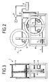
- the drawing device 5 shown in the drawing works with a pull rope 7, which is coupled in the pull-in pit 3 with both the old pipe 1 and the new pipe 2, the old pipe 1 being pressed and the new pipe 2 being pulled during the drawing process.
- the pulling force required to loosen the old pipe 1 is approximately 60 t.
- the pull rope 7 can, for. B. loop around the drive wheel 8 several times as in a capstan (FIG. 7). But you can also provide the rope 7 with steel compression clamps 9 and provide appropriately designed driver plates 10 on the drive wheel 8. The rope is then carried along smoothly and can then be wound onto a rope drum 11, as can be seen in FIGS. 2 and 3 or 4, 5 and 6.
- the pull rope 7 is designed as a double rope (FIG. 6), the rope clamp of course having a smaller diameter than the old pipe 1 must have.
- Another modification is to design the cable drum 11 as a direct drive by providing it with hydraulic motors 12 and drive gear wheels 13. In this way, the entire force is transmitted via the cable drum, where the cable end is fixed, to the pull cable 7, so that the drive wheel 8 would then only have the function of a diversion roller, with cable clamps 9 and driver plates 10 becoming superfluous.
- An advantage of the rope drum is an initially high moment at low speed, then with several wraps and thus a larger diameter, a smaller moment at higher speed.
- the drive takes place by means of hydraulic motors 12 and drive gear wheels 13.
- a hydraulic pump 14, a hydraulic control block 15 and a hydraulic oil tank 16 are indicated in FIG.
- a cutting funnel 17 continuously crushes the old tube 1 that has been pushed out into the target construction pit 4.
- a machine frame 18 is used to anchor the entire pulling device 5 in the target pit 4.
- a special system construction has been developed for accommodating the pulling device 5 in order to fix the pulling device 5 in such a way that all measures are derived into the ground can.
- the end walls of the system structure are designed as steel abutment plates 19, each with a pipe opening 20 for the old pipe 1 to be removed and a receptacle 2 for the machine frame 18.
- the side shoring consists of one Steel frame 22 made of vertical U-iron 23 with horizontal wooden planks 24 and 4 threaded sleeves 25 each with locking rods in order to ensure that the abutment plates 19 fit perfectly against the ground and thus ensure that the forces are ideally applied.
- a common pulling device for the old pipe 1 and the new pipe 2 is of essential importance for the invention, in order to reliably transmit the force of about 60 t which is required to loosen the old pipes 1.
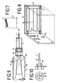
- An exemplary embodiment is shown in FIGS. 9 and 10.
- the traction cable 7 is guided through the pipe 1 to be pulled out before the actual pulling process and coupled at the tail end to a special device 26 for power transmission and for the simultaneous pulling of a new pipe 2.
- the device 26 for power transmission sits in a form-fitting manner in the old pipe 1 to be pulled out, the power transmission taking place via a threaded fitting 27 pressed onto the pull cable 7.
- different expansion cones 28 can be screwed on, as is indicated in FIGS. 9 and 10 by two bores and screws.
- the head end of the pipe to be tightened is fixed with a wedge clamping device 29, the central cone of which in turn is screwed to the expansion cone 28.
- the threaded fitting 27 of the pull cable 7 is firmly screwed into a threaded bore 30 of the device 26.
- the pipe 1 which is preferably made of cast iron, is continuously broken in front of the drive wheel 8 in a cutting funnel 17.
- the cutting knives tapering in the pulling direction cause relatively small fragments which fall over a chute onto a continuous conveyor and out of the target construction pit 4 into a collection containers are promoted.
- the traction cable 7 running from the drive wheel 8 is wound on a cable drum 11 which is under a slight pretension.
- the expansion cone 28 is arranged between the two, which usually has an angle of 30 °. In order to reduce the skin friction of the new tube 2, the expansion cone 28 is dimensioned with an overcut 31 with respect to the outer diameter of the new tube 2.
- the method and device according to the present invention are also suitable for drawing ductile cast iron pipes as new pipe material.
- the length of the continuous pulling process is then only about 6 m, but that too would be a decisive advantage over the conventional methods.
- the new pipe to be retightened should be "pressed” in the same way as the old pipe, since tensile connections are difficult with ductile iron pipes.
- For tightening ("pressing") we recommend a chain fixed to the expansion cone (28), which is passed through the new pipe and fastened under tension at the end.
Landscapes
- Engineering & Computer Science (AREA)
- General Engineering & Computer Science (AREA)
- Mechanical Engineering (AREA)
- Excavating Of Shafts Or Tunnels (AREA)
Applications Claiming Priority (2)
| Application Number | Priority Date | Filing Date | Title |
|---|---|---|---|
| DE3912728 | 1989-04-15 | ||
| DE3912728A DE3912728C1 (enExample) | 1989-04-15 | 1989-04-15 |
Publications (1)
| Publication Number | Publication Date |
|---|---|
| EP0393803A1 true EP0393803A1 (de) | 1990-10-24 |
Family
ID=6378923
Family Applications (1)
| Application Number | Title | Priority Date | Filing Date |
|---|---|---|---|
| EP90250097A Withdrawn EP0393803A1 (de) | 1989-04-15 | 1990-04-12 | Verfahren und Vorrichtung zum Auswechseln im Erdreich verlegter Rohrleitungen |
Country Status (4)
| Country | Link |
|---|---|
| EP (1) | EP0393803A1 (enExample) |
| DD (1) | DD293630A5 (enExample) |
| DE (1) | DE3912728C1 (enExample) |
| WO (1) | WO1990012978A1 (enExample) |
Cited By (3)
| Publication number | Priority date | Publication date | Assignee | Title |
|---|---|---|---|---|
| US5328297A (en) * | 1993-04-09 | 1994-07-12 | Trenchless Replacement Systems Ltd. | Trenchless replacement of smaller diameter lateral pipe sections |
| GB2299647A (en) * | 1995-04-07 | 1996-10-09 | A W Spooner & Co Ltd | Replacement pipe laying system |
| FR2789146A1 (fr) * | 1999-02-02 | 2000-08-04 | Sade Compagnie Generale De Tra | Procede et dispositif pour faciliter l'extraction d'une conduite enterree |
Families Citing this family (5)
| Publication number | Priority date | Publication date | Assignee | Title |
|---|---|---|---|---|
| GB9026450D0 (en) * | 1990-12-05 | 1991-01-23 | Tate Pipe Lining Processes Lim | Water distribution systems |
| DE19513181A1 (de) * | 1995-03-31 | 1996-10-02 | Siegfried Schwert | Verfahren und Vorrichtung zum Ziehen eines im Erdreich verlegten oder zu verlegenden Rohres |
| DE19948649C1 (de) * | 1999-09-29 | 2001-05-17 | Berliner Wasserbetriebe | Verfahren zur grabenlosen Auswechselung erdverlegter Rohrleitungen |
| DE102004059525A1 (de) * | 2004-12-09 | 2006-06-14 | Endress + Hauser Flowtec Ag | Einzugvorrichtung für eine Rohrauskleidung |
| HK1252593A2 (zh) * | 2018-04-19 | 2019-05-31 | 香港中华煤气有限公司 | 管道更换方法 |
Citations (5)
| Publication number | Priority date | Publication date | Assignee | Title |
|---|---|---|---|---|
| US2297164A (en) * | 1941-07-01 | 1942-09-29 | Daniel L Roberts Jr | Pipe replacing apparatus |
| US3181302A (en) * | 1959-08-28 | 1965-05-04 | William R Lindsay | Pipe splitier and spreader |
| US4637756A (en) * | 1985-01-23 | 1987-01-20 | Boles Flounoy W | Apparatus for removing and replacing pipe beneath an earthfill |
| DE8714724U1 (de) * | 1987-09-30 | 1988-02-18 | Karl Weiss GmbH & Co, Hoch-, Tief- und Rohrleitungsbau, 1000 Berlin | Vorrichtung zum Auswechseln von Rohren |
| DE8807589U1 (de) * | 1988-06-08 | 1988-07-21 | Berliner Wasser-Betriebe Eigenbetrieb von Berlin, 1000 Berlin | Rohrziehgerät |
-
1989
- 1989-04-15 DE DE3912728A patent/DE3912728C1/de not_active Expired
-
1990
- 1990-04-12 DD DD90339751A patent/DD293630A5/de not_active IP Right Cessation
- 1990-04-12 EP EP90250097A patent/EP0393803A1/de not_active Withdrawn
- 1990-04-12 WO PCT/DE1990/000291 patent/WO1990012978A1/de not_active Ceased
Patent Citations (5)
| Publication number | Priority date | Publication date | Assignee | Title |
|---|---|---|---|---|
| US2297164A (en) * | 1941-07-01 | 1942-09-29 | Daniel L Roberts Jr | Pipe replacing apparatus |
| US3181302A (en) * | 1959-08-28 | 1965-05-04 | William R Lindsay | Pipe splitier and spreader |
| US4637756A (en) * | 1985-01-23 | 1987-01-20 | Boles Flounoy W | Apparatus for removing and replacing pipe beneath an earthfill |
| DE8714724U1 (de) * | 1987-09-30 | 1988-02-18 | Karl Weiss GmbH & Co, Hoch-, Tief- und Rohrleitungsbau, 1000 Berlin | Vorrichtung zum Auswechseln von Rohren |
| DE8807589U1 (de) * | 1988-06-08 | 1988-07-21 | Berliner Wasser-Betriebe Eigenbetrieb von Berlin, 1000 Berlin | Rohrziehgerät |
Cited By (3)
| Publication number | Priority date | Publication date | Assignee | Title |
|---|---|---|---|---|
| US5328297A (en) * | 1993-04-09 | 1994-07-12 | Trenchless Replacement Systems Ltd. | Trenchless replacement of smaller diameter lateral pipe sections |
| GB2299647A (en) * | 1995-04-07 | 1996-10-09 | A W Spooner & Co Ltd | Replacement pipe laying system |
| FR2789146A1 (fr) * | 1999-02-02 | 2000-08-04 | Sade Compagnie Generale De Tra | Procede et dispositif pour faciliter l'extraction d'une conduite enterree |
Also Published As
| Publication number | Publication date |
|---|---|
| DE3912728C1 (enExample) | 1989-11-02 |
| DD293630A5 (de) | 1991-09-05 |
| WO1990012978A1 (de) | 1990-11-01 |
Similar Documents
| Publication | Publication Date | Title |
|---|---|---|
| DE3733463C1 (en) | Process and apparatus for exchanging pipes | |
| DE29612637U1 (de) | Vorrichtung zum Ziehen eines im Erdreich verlegten oder zu verlegenden Rohres | |
| DE3912728C1 (enExample) | ||
| EP0745175A1 (de) | Verfahren zum ausbau eines erdkerns aus einem grabenlos verlegten rohr und molch zur durchführung des verfahrens | |
| DE69124364T2 (de) | Vorschubfahrzeug für ein kontinuierlich arbeitendes abbaugerät | |
| EP0735303A1 (de) | Verfahren zum Verlegen von Rohrleitungen im Erdreich zwischen Kontrollschächten | |
| DE3513578C1 (de) | Schneckenfördereinrichtung für eine Vorrichtung zum unterirdischen Vorpressen von Rohrschüssen | |
| DE3603238C2 (enExample) | ||
| DE4241856C1 (de) | Rohrverlegung mit mitlaufender Vortriebspresse | |
| DE19829667C1 (de) | Verfahren zum Auswechseln im Erdreich verlegter Rohre | |
| DE3729561C2 (enExample) | ||
| AT509158B1 (de) | Vorrichtung zum entfernen oder zum auswechseln von kabeln | |
| DE2817017C2 (de) | Horizontalpreßbohrgerät | |
| DE19962298C2 (de) | Einpressvorrichtung für Rohre und Bohrgestänge | |
| DE1811421A1 (de) | Verfahren zum Verlegen von Kabeln und Rohren in Fahrbahnkoerpern | |
| EP4357532B1 (de) | Verfahren zur einbringung eines gewindestabes in einen untergrund, sowie eindrehsystem hierfür | |
| DE2242599C3 (de) | Einrichtung zum Ziehen von Bohrrohren | |
| DE2154196B2 (de) | Vortriebsmaschine | |
| DE3902845C1 (en) | Method and device for exchanging a pipe in a freely suspended pipeline | |
| DE3411231C1 (de) | Vorrichtung zum Einrammen von Stahlrohren ins Erdreich | |
| CH643474A5 (de) | Vorrichtung an stranggiessanlage zum vorschub des gussstranges. | |
| DE2109384A1 (de) | Verfahren zur herstellung unterirdischer bauwerke von nennweiten unter vier metern im schildvortrieb und vortriebsschild fuer dieses verfahren | |
| DE3016793C3 (enExample) | ||
| DE602120C (de) | Verfahren und Vorrichtung zum Lockern einer in der Querrichtung mehrteiligen kegeligen Rammjungfer | |
| DE1920322B2 (de) | Vorri chtung zum loesen und laden des anstehenden erdreichs beim rohrvorpressen |
Legal Events
| Date | Code | Title | Description |
|---|---|---|---|
| PUAI | Public reference made under article 153(3) epc to a published international application that has entered the european phase |
Free format text: ORIGINAL CODE: 0009012 |
|
| AK | Designated contracting states |
Kind code of ref document: A1 Designated state(s): AT BE CH DE FR GB IT LI LU NL SE |
|
| STAA | Information on the status of an ep patent application or granted ep patent |
Free format text: STATUS: THE APPLICATION IS DEEMED TO BE WITHDRAWN |
|
| 18D | Application deemed to be withdrawn |
Effective date: 19910425 |