EP0393773B1 - Transporteur - Google Patents
Transporteur Download PDFInfo
- Publication number
- EP0393773B1 EP0393773B1 EP90200922A EP90200922A EP0393773B1 EP 0393773 B1 EP0393773 B1 EP 0393773B1 EP 90200922 A EP90200922 A EP 90200922A EP 90200922 A EP90200922 A EP 90200922A EP 0393773 B1 EP0393773 B1 EP 0393773B1
- Authority
- EP
- European Patent Office
- Prior art keywords
- carrier
- motor
- carrying means
- driven
- conveyor
- Prior art date
- Legal status (The legal status is an assumption and is not a legal conclusion. Google has not performed a legal analysis and makes no representation as to the accuracy of the status listed.)
- Expired - Lifetime
Links
Images


Classifications
-
- B—PERFORMING OPERATIONS; TRANSPORTING
- B65—CONVEYING; PACKING; STORING; HANDLING THIN OR FILAMENTARY MATERIAL
- B65G—TRANSPORT OR STORAGE DEVICES, e.g. CONVEYORS FOR LOADING OR TIPPING, SHOP CONVEYOR SYSTEMS OR PNEUMATIC TUBE CONVEYORS
- B65G17/00—Conveyors having an endless traction element, e.g. a chain, transmitting movement to a continuous or substantially-continuous load-carrying surface or to a series of individual load-carriers; Endless-chain conveyors in which the chains form the load-carrying surface
- B65G17/30—Details; Auxiliary devices
- B65G17/32—Individual load-carriers
- B65G17/34—Individual load-carriers having flat surfaces, e.g. platforms, grids, forks
- B65G17/345—Individual load-carriers having flat surfaces, e.g. platforms, grids, forks the surfaces being equipped with a conveyor
-
- B—PERFORMING OPERATIONS; TRANSPORTING
- B65—CONVEYING; PACKING; STORING; HANDLING THIN OR FILAMENTARY MATERIAL
- B65G—TRANSPORT OR STORAGE DEVICES, e.g. CONVEYORS FOR LOADING OR TIPPING, SHOP CONVEYOR SYSTEMS OR PNEUMATIC TUBE CONVEYORS
- B65G2201/00—Indexing codes relating to handling devices, e.g. conveyors, characterised by the type of product or load being conveyed or handled
- B65G2201/02—Articles
-
- B—PERFORMING OPERATIONS; TRANSPORTING
- B65—CONVEYING; PACKING; STORING; HANDLING THIN OR FILAMENTARY MATERIAL
- B65G—TRANSPORT OR STORAGE DEVICES, e.g. CONVEYORS FOR LOADING OR TIPPING, SHOP CONVEYOR SYSTEMS OR PNEUMATIC TUBE CONVEYORS
- B65G2207/00—Indexing codes relating to constructional details, configuration and additional features of a handling device, e.g. Conveyors
- B65G2207/18—Crossing conveyors
Definitions
- the invention relates to a conveyor provided with a frame, with an endless carrying means supported by the frame, which can be driven in its longitudinal direction, and with a plurality of carriers coupled to said carrying means, which are each suitable for accommodating one or more objects, and which are each provided with a displacement means, which can be driven by means of a motor provided on the carrier and by means of which an object present on a carrier can be moved transversely to the longitudinal direction of the carrying means.
- the aim of the invention is to obtain a conveyor of the above kind, wherein the above disadvantages can be avoided.
- each carrier is provided with a means generating energy for driving the motor, whereby the driving of the energy generating means is effected by the relative movement between the carrier and the frame when the carrying means is being driven.
- a current generator may constitute the energy generating means.
- the motor is a hydraulic motor
- a hydraulic pump may be used as an energy generating means.
- each carrier is provided with a mechanism which co-operates with the displacement means formed by an endless belt for moving said displacement means with respect to the carrier.
- the mechanism guide means in the shape of guide strips extending obliquely to the direction of movement of the carrying means and being fixed to the frame, are provided at desired places. Apart from its complicated design such a construction will produce a great deal of noise during operation, which is generally undesirable, whilst furthermore much wear will occur on the co-operating parts being in engagement with each other.
- FIGS 10 - 12 of said US Patent Specification illustrate an embodiment wherein the transverse transporters can be driven via conical gear transmissions and vertically adjustable racks.
- Said embodiments have a complicated and heavy construction, they will produce a great deal of noise during operation and will be very liable to wear.
- a fourth embodiment proposed in US-A-3,231,068 at least substantially corresponds with the embodiments according to FR-A-2,475,015 ( Figure 2) and GB-A-2,140,371 and consequently has the above-mentioned disadvantages of said known devices.
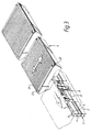
- the embodiment of the conveyor according to the invention illustrated in the figures comprises a plurality of stands 1 arranged spaced from each other, which support a guide rail formed by two profile beams 2 and 3, which guide rail will form a closed loop in a manner known per se.
- the profile beams are at least substantially formed by vertical webs 4 and 5 respectively, and strip-shaped ribs 6 and 7 respectively being integral with said webs and extending perpendicularly to said webs, said ribs extending from the webs 4 and 5 respectively in a direction towards one another.
- the device furthermore comprises and endless carrying means 8, which is provided with a plurality of spaced link parts 9. To the ends of said link parts there are coupled further link parts 11, by means of pins 10 extending perpendicularly to the longitudinal direction of the link parts and extending vertically, when seen in Figure 2, in such a manner that the link parts 9 and 11 can pivot relative to each other about the central axes of the pins 10.
- the endless carrying means 8 formed by the link parts 9 and 11 and the links 12 is arranged between the two profile beams 2 and 3 forming the conductor rail for the carrying means 8.
- the guide rolls 15 are supported on ribs 6 and 7 of the profile beams 2 and 3 thereby, whilst the guide rolls 16 co-operate with the facing boundary planes of the webs 4 and 5 of the profile beams 2 and 3. It will be apparent, that thus the guide rolls 15 and 16 ensure a good guiding of the carrying means 8 in the rail formed by the profile beams 2 and 3, when during operation the carrying means 8 is moved, by means of a driving means to be described hereinafter, in the direction according to arrow A.
- the endless means may be led along a path which may be deflected both horizontally and vertically.
- the link parts 9 and 11 and the links 12 are on both sides provided with flat boundary planes 17, 18 and 19 respectively, said boundary planes being in line and extending along at least part of the height of said parts and in the longitudinal direction of said parts.
- Wheels 20 and 21, arranged on both sides of the carrying means 8 and supported by the frame engage said boundary planes, as is indicated by dotted lines in Figure 1.
- Preferably at least the peripheral surface of said wheels is slightly resilient. Wheels having pneumatic tyres can be efficiently used.
- At least one of the wheels 20 or 21 can be driven, by means of a motor (not shown), in order to effect a movement of the carrying means 8 in the direction according to arrow A.
- the link part 9 forms a carrier which supports a pair of rolls 22 and 23 near its upper end in the illustrated embodiment.
- An endless conveyor belt 24 is carried over said rolls in the illustrated embodiment, the width of said endless conveyor belt substantially corresponding with the length of the upper part of the carrier 9.
- Each carrier supports an electromotor 25, which is coupled to the roll 22 by means of a belt drive 26.
- a current generator 27 is furthermore secured to the carrier 9.
- a gear 28 which is coupled to a gear 30 via a toothed belt 29, said gear 30 being secured to a shaft 31 supported by the carrier 9.
- a wheel 32 supported on the upper flange 7 of the profile beam 3.
- one or more objects can be placed, in one or more stations, on the carriers 9 led along said stations, by placing said objects, in a manner known per se, on the conveyor belts 24 of the carriers 9 by means of additional conveyors, by hand or the like.
- the displacement means formed by the conveyor belts 24 will be moved, by means of the electromotor 25, at desired places along the path described by the endless carrying means, in order to discharge the objects present on said conveyor belts (24) transversely to the direction of movement of the endsless carrying means 8.
- the construction will be such that when the objects are being received the conveyor belts 24 will be moved along a small distance at a comparatively low speed, whereas the conveyor belts will be moved at a comparatively high speed when the objects are being discharged.
- the conveyor belts 24 are only driven intermittently and very briefly during normal operation, however, so that said driving requires comparatively very little energy. It will be possible, however, for the generator 27 to be driven continuously, as long as the carrying means 8 is driven during operation of the device, so that there is amply sufficient time in between the periods when the motor 25 is operated to generate the energy required for operating the motor by means of the generator 27 and supply said energy to the battery or the capacitor 33.
- the control mechanism operating the motor 25 can e.g. be activated by means of optical sensors arranged along the path of the carrying means, which optical sensors are arranged along the path travelled by the carrying means, or by feelers arranged along said path and co-operating with the carriers, or by measuring means, which emit signals to the control mechanism 34 in dependence on the path travelled by a relevant carrier 9.
- the displacement means formed by the conveyor belt in the embodiment described may also take other forms, of course. Thus it is conceivable to use several belts located side by side, as well as a wipe-off means which is movable to and fro across an upper supporting surface of the carrier 9 intended for accommodating the objects.
Landscapes
- Engineering & Computer Science (AREA)
- Mechanical Engineering (AREA)
- Chain Conveyers (AREA)
- Advancing Webs (AREA)
- Pharmaceuticals Containing Other Organic And Inorganic Compounds (AREA)
- Materials For Medical Uses (AREA)
Claims (6)
Priority Applications (1)
| Application Number | Priority Date | Filing Date | Title |
|---|---|---|---|
| AT90200922T ATE73412T1 (de) | 1989-04-19 | 1990-04-13 | Foerderer. |
Applications Claiming Priority (2)
| Application Number | Priority Date | Filing Date | Title |
|---|---|---|---|
| NL8900975A NL8900975A (nl) | 1989-04-19 | 1989-04-19 | Transportinrichting. |
| NL8900975 | 1989-04-19 |
Publications (2)
| Publication Number | Publication Date |
|---|---|
| EP0393773A1 EP0393773A1 (fr) | 1990-10-24 |
| EP0393773B1 true EP0393773B1 (fr) | 1992-03-11 |
Family
ID=19854501
Family Applications (1)
| Application Number | Title | Priority Date | Filing Date |
|---|---|---|---|
| EP90200922A Expired - Lifetime EP0393773B1 (fr) | 1989-04-19 | 1990-04-13 | Transporteur |
Country Status (4)
| Country | Link |
|---|---|
| EP (1) | EP0393773B1 (fr) |
| AT (1) | ATE73412T1 (fr) |
| DE (1) | DE69000030D1 (fr) |
| NL (1) | NL8900975A (fr) |
Cited By (2)
| Publication number | Priority date | Publication date | Assignee | Title |
|---|---|---|---|---|
| EP0739831A2 (fr) * | 1995-04-25 | 1996-10-30 | Crisplant A/S | Transporteur |
| EP1041019A2 (fr) | 1999-03-30 | 2000-10-04 | Beumer Maschinenfabrik GmbH & Co. KG | Dispositif pour transporter des objets |
Families Citing this family (6)
| Publication number | Priority date | Publication date | Assignee | Title |
|---|---|---|---|---|
| NL1015417C2 (nl) | 2000-06-13 | 2001-12-14 | Vanderlande Ind Nederland | Transportinrichting. |
| DE10340868B4 (de) * | 2003-09-04 | 2005-09-29 | Siemens Ag | Fördersystem, insbesondere eine Flughafengepäckförderanlage, für zum Transport von Stückgut dienenden Behältern |
| DE102004033548B4 (de) * | 2004-07-09 | 2007-08-02 | Eisenmann Anlagenbau Gmbh & Co. Kg | Hubstation in einer Oberflächenbehandlungsanlage |
| DK177381B1 (en) | 2011-08-16 | 2013-03-04 | Crisplant As | Cross-belt sorting system |
| DE102013218377B4 (de) * | 2013-09-13 | 2016-12-22 | Siemens Aktiengesellschaft | Querbandsortertransportelement |
| CN107161614A (zh) * | 2017-06-15 | 2017-09-15 | 合肥海腾软件科技有限公司 | 大倾角带式输送机的节能装置 |
Family Cites Families (3)
| Publication number | Priority date | Publication date | Assignee | Title |
|---|---|---|---|---|
| US3231068A (en) * | 1963-01-07 | 1966-01-25 | Prospect Mfg Co Inc | Article delivery conveyer |
| IT1131422B (it) * | 1980-03-14 | 1986-06-25 | Studsvik Energiteknik Ab | Guarnizione antifiamma |
| GB2140371A (en) * | 1983-05-27 | 1984-11-28 | Francesco Canziani | Conveying devices |
-
1989
- 1989-04-19 NL NL8900975A patent/NL8900975A/nl not_active Application Discontinuation
-
1990
- 1990-04-13 EP EP90200922A patent/EP0393773B1/fr not_active Expired - Lifetime
- 1990-04-13 AT AT90200922T patent/ATE73412T1/de not_active IP Right Cessation
- 1990-04-13 DE DE9090200922T patent/DE69000030D1/de not_active Expired - Lifetime
Cited By (3)
| Publication number | Priority date | Publication date | Assignee | Title |
|---|---|---|---|---|
| EP0739831A2 (fr) * | 1995-04-25 | 1996-10-30 | Crisplant A/S | Transporteur |
| GB2300612B (en) * | 1995-04-25 | 1998-09-30 | Crisplant As | Conveyor |
| EP1041019A2 (fr) | 1999-03-30 | 2000-10-04 | Beumer Maschinenfabrik GmbH & Co. KG | Dispositif pour transporter des objets |
Also Published As
| Publication number | Publication date |
|---|---|
| EP0393773A1 (fr) | 1990-10-24 |
| DE69000030D1 (en) | 1992-04-16 |
| ATE73412T1 (de) | 1992-03-15 |
| NL8900975A (nl) | 1990-11-16 |
Similar Documents
| Publication | Publication Date | Title |
|---|---|---|
| CA2345399C (fr) | Appareil de tri a deux niveaux de plateaux basculants | |
| KR930009154B1 (ko) | 자체구동 운반대를 갖춘 물품분류장치 | |
| US5577593A (en) | Carrier conveyor system | |
| US4712670A (en) | Mechanism for the transportation of objects | |
| EP0626324B1 (fr) | Transporteur | |
| JPS5846404B2 (ja) | コンベヤソウチオヨビジザイツギテ | |
| US4352622A (en) | Warehouse crane with pin-engageable tote pans | |
| EP0393773B1 (fr) | Transporteur | |
| US6321899B1 (en) | Device for transferring goods | |
| CN112474371A (zh) | 翻板分拣机、翻板分拣系统、翻板分拣机的分拣方法及支撑导轨 | |
| US1879944A (en) | Apparatus for conveying goods in bales, sacks, or the like | |
| US3877386A (en) | Apparatus for controlling conveyance of articles | |
| US3269519A (en) | High speed take-off | |
| CN213678723U (zh) | 一种物料箱输送装置 | |
| NL193277C (nl) | Transportinrichting. | |
| CN214289413U (zh) | 翻转式分拣车、翻转式分拣装置及翻转式分拣系统 | |
| US6378423B1 (en) | Friction drive system floor conveyor | |
| KR20050054430A (ko) | 무단형 컨베이어 벨트를 이용한 물품이송시스템 | |
| CN214638276U (zh) | 翻板分拣机、翻板分拣系统及支撑导轨 | |
| US3807550A (en) | Reciprocating accumulation conveyor | |
| CN112474372A (zh) | 翻转式分拣车、翻转式分拣装置、翻转式分拣系统及翻转式分拣方法 | |
| US3568818A (en) | Conveyor for accumulating, spacing and storing articles | |
| CN216188319U (zh) | 导入输送机及分拣系统 | |
| DK168370B1 (da) | Anlæg med selvkørende vogne, til transport og sortering af emner | |
| CN220115432U (zh) | 一种链板输送装置 |
Legal Events
| Date | Code | Title | Description |
|---|---|---|---|
| PUAI | Public reference made under article 153(3) epc to a published international application that has entered the european phase |
Free format text: ORIGINAL CODE: 0009012 |
|
| AK | Designated contracting states |
Kind code of ref document: A1 Designated state(s): AT BE CH DE DK ES FR GB GR IT LI LU NL SE |
|
| 17P | Request for examination filed |
Effective date: 19901002 |
|
| 17Q | First examination report despatched |
Effective date: 19910717 |
|
| GRAA | (expected) grant |
Free format text: ORIGINAL CODE: 0009210 |
|
| ITF | It: translation for a ep patent filed |
Owner name: ING. PIOVESANA PAOLO |
|
| AK | Designated contracting states |
Kind code of ref document: B1 Designated state(s): AT BE CH DE DK ES FR GB GR IT LI LU NL SE |
|
| PG25 | Lapsed in a contracting state [announced via postgrant information from national office to epo] |
Ref country code: SE Effective date: 19920311 Ref country code: LI Effective date: 19920311 Ref country code: GR Free format text: LAPSE BECAUSE OF FAILURE TO SUBMIT A TRANSLATION OF THE DESCRIPTION OR TO PAY THE FEE WITHIN THE PRESCRIBED TIME-LIMIT Effective date: 19920311 Ref country code: ES Free format text: THE PATENT HAS BEEN ANNULLED BY A DECISION OF A NATIONAL AUTHORITY Effective date: 19920311 Ref country code: DK Effective date: 19920311 Ref country code: CH Effective date: 19920311 Ref country code: AT Effective date: 19920311 |
|
| REF | Corresponds to: |
Ref document number: 73412 Country of ref document: AT Date of ref document: 19920315 Kind code of ref document: T |
|
| REF | Corresponds to: |
Ref document number: 69000030 Country of ref document: DE Date of ref document: 19920416 |
|
| ET | Fr: translation filed | ||
| REG | Reference to a national code |
Ref country code: CH Ref legal event code: PL |
|
| PLBE | No opposition filed within time limit |
Free format text: ORIGINAL CODE: 0009261 |
|
| STAA | Information on the status of an ep patent application or granted ep patent |
Free format text: STATUS: NO OPPOSITION FILED WITHIN TIME LIMIT |
|
| 26N | No opposition filed | ||
| EPTA | Lu: last paid annual fee | ||
| NLT1 | Nl: modifications of names registered in virtue of documents presented to the patent office pursuant to art. 16 a, paragraph 1 |
Owner name: VANDERLANDE INDUSTRIES NEDERLAND B.V. |
|
| REG | Reference to a national code |
Ref country code: FR Ref legal event code: CD |
|
| PGFP | Annual fee paid to national office [announced via postgrant information from national office to epo] |
Ref country code: GB Payment date: 20010411 Year of fee payment: 12 |
|
| PGFP | Annual fee paid to national office [announced via postgrant information from national office to epo] |
Ref country code: NL Payment date: 20010427 Year of fee payment: 12 |
|
| PGFP | Annual fee paid to national office [announced via postgrant information from national office to epo] |
Ref country code: DE Payment date: 20010605 Year of fee payment: 12 |
|
| REG | Reference to a national code |
Ref country code: GB Ref legal event code: IF02 |
|
| PGFP | Annual fee paid to national office [announced via postgrant information from national office to epo] |
Ref country code: LU Payment date: 20020131 Year of fee payment: 13 |
|
| PGFP | Annual fee paid to national office [announced via postgrant information from national office to epo] |
Ref country code: FR Payment date: 20020227 Year of fee payment: 13 |
|
| PGFP | Annual fee paid to national office [announced via postgrant information from national office to epo] |
Ref country code: BE Payment date: 20020305 Year of fee payment: 13 |
|
| PG25 | Lapsed in a contracting state [announced via postgrant information from national office to epo] |
Ref country code: GB Free format text: LAPSE BECAUSE OF NON-PAYMENT OF DUE FEES Effective date: 20020413 |
|
| PG25 | Lapsed in a contracting state [announced via postgrant information from national office to epo] |
Ref country code: NL Free format text: LAPSE BECAUSE OF NON-PAYMENT OF DUE FEES Effective date: 20021101 Ref country code: DE Free format text: LAPSE BECAUSE OF NON-PAYMENT OF DUE FEES Effective date: 20021101 |
|
| GBPC | Gb: european patent ceased through non-payment of renewal fee |
Effective date: 20020413 |
|
| NLV4 | Nl: lapsed or anulled due to non-payment of the annual fee |
Effective date: 20021101 |
|
| PG25 | Lapsed in a contracting state [announced via postgrant information from national office to epo] |
Ref country code: LU Free format text: LAPSE BECAUSE OF NON-PAYMENT OF DUE FEES Effective date: 20030413 |
|
| PG25 | Lapsed in a contracting state [announced via postgrant information from national office to epo] |
Ref country code: BE Free format text: LAPSE BECAUSE OF NON-PAYMENT OF DUE FEES Effective date: 20030430 |
|
| BERE | Be: lapsed |
Owner name: *VANDERLANDE INDUSTRIES NEDERLAND B.V. Effective date: 20030430 |
|
| PG25 | Lapsed in a contracting state [announced via postgrant information from national office to epo] |
Ref country code: FR Free format text: LAPSE BECAUSE OF NON-PAYMENT OF DUE FEES Effective date: 20031231 |
|
| REG | Reference to a national code |
Ref country code: FR Ref legal event code: ST |
|
| PG25 | Lapsed in a contracting state [announced via postgrant information from national office to epo] |
Ref country code: IT Free format text: LAPSE BECAUSE OF NON-PAYMENT OF DUE FEES;WARNING: LAPSES OF ITALIAN PATENTS WITH EFFECTIVE DATE BEFORE 2007 MAY HAVE OCCURRED AT ANY TIME BEFORE 2007. THE CORRECT EFFECTIVE DATE MAY BE DIFFERENT FROM THE ONE RECORDED. Effective date: 20050413 |