EP0393410A2 - Aircraft with a pair of contra-rotating propellers - Google Patents
Aircraft with a pair of contra-rotating propellers Download PDFInfo
- Publication number
- EP0393410A2 EP0393410A2 EP90106212A EP90106212A EP0393410A2 EP 0393410 A2 EP0393410 A2 EP 0393410A2 EP 90106212 A EP90106212 A EP 90106212A EP 90106212 A EP90106212 A EP 90106212A EP 0393410 A2 EP0393410 A2 EP 0393410A2
- Authority
- EP
- European Patent Office
- Prior art keywords
- sectors
- rotors
- aircraft according
- aircraft
- rotor
- Prior art date
- Legal status (The legal status is an assumption and is not a legal conclusion. Google has not performed a legal analysis and makes no representation as to the accuracy of the status listed.)
- Granted
Links
- 241000446313 Lamella Species 0.000 claims description 20
- 238000000034 method Methods 0.000 description 7
- 230000008569 process Effects 0.000 description 7
- 230000007704 transition Effects 0.000 description 4
- 238000010276 construction Methods 0.000 description 3
- 239000007789 gas Substances 0.000 description 3
- 229920001971 elastomer Polymers 0.000 description 2
- 230000005484 gravity Effects 0.000 description 2
- 230000001141 propulsive effect Effects 0.000 description 2
- 206010000369 Accident Diseases 0.000 description 1
- 229920000049 Carbon (fiber) Polymers 0.000 description 1
- 239000004917 carbon fiber Substances 0.000 description 1
- 238000006243 chemical reaction Methods 0.000 description 1
- 238000013016 damping Methods 0.000 description 1
- 230000007423 decrease Effects 0.000 description 1
- 238000006073 displacement reaction Methods 0.000 description 1
- 230000000694 effects Effects 0.000 description 1
- 239000000806 elastomer Substances 0.000 description 1
- 239000002828 fuel tank Substances 0.000 description 1
- 230000005283 ground state Effects 0.000 description 1
- 230000003993 interaction Effects 0.000 description 1
- 239000003562 lightweight material Substances 0.000 description 1
- 239000000463 material Substances 0.000 description 1
- VNWKTOKETHGBQD-UHFFFAOYSA-N methane Chemical compound C VNWKTOKETHGBQD-UHFFFAOYSA-N 0.000 description 1
- 230000007935 neutral effect Effects 0.000 description 1
- 229920001084 poly(chloroprene) Polymers 0.000 description 1
- 239000002990 reinforced plastic Substances 0.000 description 1
- 238000005096 rolling process Methods 0.000 description 1
- 239000007787 solid Substances 0.000 description 1
- 239000003381 stabilizer Substances 0.000 description 1
- 230000000087 stabilizing effect Effects 0.000 description 1
Images


Classifications
-
- B—PERFORMING OPERATIONS; TRANSPORTING
- B64—AIRCRAFT; AVIATION; COSMONAUTICS
- B64C—AEROPLANES; HELICOPTERS
- B64C27/00—Rotorcraft; Rotors peculiar thereto
- B64C27/20—Rotorcraft characterised by having shrouded rotors, e.g. flying platforms
-
- B—PERFORMING OPERATIONS; TRANSPORTING
- B64—AIRCRAFT; AVIATION; COSMONAUTICS
- B64C—AEROPLANES; HELICOPTERS
- B64C27/00—Rotorcraft; Rotors peculiar thereto
- B64C27/04—Helicopters
- B64C27/08—Helicopters with two or more rotors
- B64C27/10—Helicopters with two or more rotors arranged coaxially
-
- B—PERFORMING OPERATIONS; TRANSPORTING
- B64—AIRCRAFT; AVIATION; COSMONAUTICS
- B64C—AEROPLANES; HELICOPTERS
- B64C29/00—Aircraft capable of landing or taking-off vertically, e.g. vertical take-off and landing [VTOL] aircraft
- B64C29/0008—Aircraft capable of landing or taking-off vertically, e.g. vertical take-off and landing [VTOL] aircraft having its flight directional axis horizontal when grounded
- B64C29/0016—Aircraft capable of landing or taking-off vertically, e.g. vertical take-off and landing [VTOL] aircraft having its flight directional axis horizontal when grounded the lift during taking-off being created by free or ducted propellers or by blowers
- B64C29/0025—Aircraft capable of landing or taking-off vertically, e.g. vertical take-off and landing [VTOL] aircraft having its flight directional axis horizontal when grounded the lift during taking-off being created by free or ducted propellers or by blowers the propellers being fixed relative to the fuselage
-
- B—PERFORMING OPERATIONS; TRANSPORTING
- B64—AIRCRAFT; AVIATION; COSMONAUTICS
- B64C—AEROPLANES; HELICOPTERS
- B64C39/00—Aircraft not otherwise provided for
- B64C39/001—Flying saucers
Definitions
- the invention relates to an aircraft with an oppositely rotating pair of rotors for generating lift and propulsion.
- Aircraft of this type are generally known in the form of helicopters.
- helicopters are known which have several rotors rotating in opposite directions, which results in a torque compensation between the rotors. As is known, these can be arranged one above the other.
- the rotor axis is located in the center of gravity of the aircraft, which limits the usable space.
- the mechanical design of the drive and control is extremely complex, particularly in the case of rotors arranged one above the other.
- the control functions are complicated and require great skill.
- the speed in forward flight is limited by the asymmetry of the flow against the rotor blades and the resulting mechanical loads on the rotors. After all, the free rotors are often the cause of aircraft accidents, since even the slightest contact with solid objects leads to unforeseeable effects on the lift characteristics and the controllability of the aircraft.
- Rotary wing aircraft with counter-rotating rotors are known, for example, from Swiss Patent No. 558 737, from Australian PS No. 474 805 and from US Pat. Nos. 2,777,649, 2,395,876 and 2,461,435, the rotors being partially arranged within a housing and air ducts being provided.
- the arrangement of the air ducts or fins does not allow safe control of the flight positions and movements of these aircraft in hover. Further the control processes are confusing and complicated, so that difficulties in mastering these aircraft may occur in practical operation.
- the object is to create an aircraft of the type mentioned at the outset which does not have these disadvantages and which, in particular, enables two flight states, namely a helicopter-like hover and a surface flight, without control problems occurring.
- this object is achieved by the features of claim 1.
- the mutually opposing arrangement of the blades in the sectors active during hover allows a controlled hover without unwanted propulsion components.
- the air ducts preferably have propulsion areas in which the blades can be controlled in the same direction with respect to the rotor beam. These areas are used to generate propulsion in surface flight and hover as well as to control the position around the vertical axis in hover.
- controllable air ducts are sector-oriented, tangentially extending slats, the slat sectors each comprising approximately 30 degrees and each having a control drive, the control drives being interconnectable in groups according to the control signals.
- the movement of the aircraft can be controlled in a simple manner by suitable interaction of the deflection of the rotor beam in each of the interconnected groups.
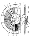
- the basic element is a housing 1, in which a pair of rotors 2, 3 is arranged, which is driven in opposite directions.
- the housing 1 itself is disc-shaped. In its longitudinal cross-section, it has a profile that generates lift when the flow is against it, while it is essentially circular in plan.
- the housing thus forms a circular wing which, in addition to hovering, also permits flight conditions which correspond to those of fixed-wing aircraft, ie. powered forward flight or gliding flight.
- the propulsion is at least to a considerable extent by the pair of rotors 2, 3 with appropriate deflections and guidance of the rotor beam, as will be explained in more detail.
- a cabin 9 is provided for receiving the drive unit 8, the pilot, the passengers and the payload.
- the cabin 9 is radially delimited by a twelve-sided, cylindrical support part 4, on which struts 17 with a triangular profile lead in the radial direction to an annular outer part 7.
- the elements mentioned together form a load-bearing, rigid structure. They are preferably made of high-strength, lightweight material, such as e.g. carbon fiber or Kevlar-reinforced plastic.
- the cylindrical support part 4 forms a central, open space in which the cabin 9 is formed, which in the exemplary embodiment shown is mainly in the rotor plane in the inner part 4 itself, is accessible from above and offers space for two people.
- the drive and control units are located in the lower or rear area of the inner part 4 in the direction of flight.
- Bearing rollers 11 are provided on the supporting part 4, on which the rotors 2, 3 with their inner drive rings 12 are mounted, as can be seen in particular from FIG. 5. To absorb axial forces, these bearings 11 are set at an angle to the rotor plane.
- the drive rings 12 can advantageously directly form parts of the bearing itself.
- Fixed guides 10 are provided on the annular outer part 7, on which outer rollers 34 run, which are arranged on the outside of the rotor blades (cf. FIG. 2).
- the outer guides 10 and the run-off surfaces of the bearing rollers are provided with a noise-damping elastomer material, for example a resistant rubber such as neoprene.
- a noise-damping elastomer material for example a resistant rubber such as neoprene.
- the outer guidance of the rotor blades can be dispensed with if they are designed to be sufficiently rigid so that their deflection under load remains within the tolerances given by the design.
- each rotor which, according to the embodiments shown here, each rotor extend between the inner drive ring 12 and the outer guide 10, have a suitable, buoyancy-generating blade profile.
- the rotors 2, 3 are driven by means of a common unit 8, which is arranged in the cylindrical inner part 4.
- the unit is a piston engine with an output of e.g. 220 WPS. This drives two gears 19 via a gear, which mesh in the two drive rings 12 of the rotors 2, 3.
- Another exemplary embodiment with a jet turbine drive will be explained with reference to FIGS. 6 and 7.
- the drive causes the rotor to rotate in exactly the opposite direction, which leads to complete torque compensation. Any residual torques that may occur on the housing 1 can be trimmed or corrected using the control system to be described.
- the housing parts above and below the rotor level are designed for sufficient air passage.
- the upper cover which does not have to have a supporting function, is formed by an outer skin 5 with air openings.
- the air inlets can be designed, for example, as mesh grids arranged in sectors.
- Below the rotor plane louvre-like, tangential, adjustable fins 16 are arranged in sectors, as shown in particular in FIG. 3 and 4 can be seen. In the exemplary embodiment shown, the sectors have angles of 30 degrees, so that a total of 12 such sectors result.
- sectors and their functions can be seen on the basis of a first embodiment variant.
- the sectors a, b, d, e, g, h, k, l belong to the first group (cf. FIG. 4).
- the slats in these sectors can be adjusted in pairs in opposite directions with respect to the rotor beam by means of cables 31, 31 '.
- the trains 31,31 ' are each connected to a servo drive 18 for slat adjustment.
- the aforementioned opposing pairwise adjustment means that the sectors mentioned in the first group do not generate a propulsion component, but rather only a certain buoyancy force in each position.
- the slats of the individual sectors can be opened more or less, so that the lifting force in the corresponding sector increases or decreases.
- the rolling motion i.e. the inclination about the longitudinal axis 32 (FIG. 4) is accomplished by the corresponding control of the sector groups b, d and h, k.
- the pitching motion in hover i.e. the inclination around the transverse axis is carried out by controlling the sector groups a, l and g, e.
- the total lifting force, which causes the aircraft to rise or fall vertically, is brought about by collective opening and closing of the aforementioned lamella groups.
- the lamellae of a second group are from Sectors m, f and c, i and optionally also individual ones of the sectors of the first group can be adjusted in the same direction, so that a corresponding horizontal propulsive force is superimposed on the buoyant force in the area of the respective sector.
- propulsion units independent of the lamella control can be provided for the horizontal surface flight, as will be explained in more detail.
- the slats of the first sector group mentioned are closed and form part of a lift-generating profile.
- the propulsion in this flight state is generated by the additional propulsion units still to be described and / or by the correspondingly inclined slats of the sectors m and f and slat groups 33.
- the latter determine the cornering behavior in surface flight by optionally changing the angle of attack to the left or right of the direction of flight 32.
- the lamella sectors m and f are also closed to improve the gliding properties.
- stabilizing wings 40 arranged in the annular outer part 7 can be extended (see FIGS. 1 and 2), which are sunk in the outer part 7 when hovering.
- the lightweight outer ring 7 of the housing optionally carries the guides 10 of the rotors and is on the struts 17 be consolidates.
- fuel tanks, a retractable roller carriage 41 and possibly additional propulsion units 42 can also be arranged (FIGS. 3, 4).
- the structure of the rotor housing 1 and outer part 7 is essentially identical in sectors, so that a modular construction with relatively few components is possible.
- the profile of the outer part 7, together with the rotor housing, is such that it generates lift in forward flight, i.e. acts as a round wing.
- hover flight A general distinction must be made between hover flight and area flight for the control behavior.
- hovering the lift and propulsion are generated by the rotors, while in gliding flight a substantial part of the lift is taken over by the correspondingly profiled housing 1 and outer ring 7 and part of the propulsion by propulsion units.
- control is also carried out in a different way, as has already been indicated.
- control elements are connected to control electronics which, according to a control program, actuate the respective servo drives 18 of the slat sectors.
- the changeover between hovering and surface flight takes place automatically depending on the forward speed as soon as the inflow speed on the housing profile ensures a corresponding lift.
- the functioning of the control elements remains unaffected by this, so that the control can be operated in the same way for both flight conditions.
- the directional stability and the horizontal position of the aircraft when the control elements are not actuated is controlled in a manner known per se by an automatic slat control Dependence of a position sensor system is observed, on which the signals of the control elements are superimposed.
- the first of the two control elements in the form of a control stick influences the horizontal displacements in hover flight, while the second control element, also in the form of a control stick, controls the inclinations about the longitudinal and transverse axes in hover flight or in flat flight.
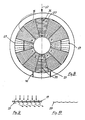
- the lamella profile can be bent in these sectors for better deflection of the rotor beam, such that a beam deflection of approximately 70 ° is accomplished, as is shown in FIG. 9 with the lamella position open towards one side and in FIG. 10 with the lamella position closed. The losses caused by the beam deflection can thus be reduced.
- the same slat groups are used for corresponding control processes in hovering and in flat flight, one from the open and the other from the essentially closed ground state.
- the second control element is intended for rotations around the three body axes, which enables the necessary control processes in surface flight.
- a recoil drive acting in the horizontal direction is provided as a variant in addition to the described lamella groups m and f and the lamella groups 33.
- This can be independent of the drive of the rotor pair, as indicated in FIGS. 3 and 4.
- two jet turbine engines 42 are arranged laterally to the main flight direction in the annular outer part.
- a flap 43 of known type is provided in the exit area for deflecting the jet in the vertical direction during hovering.
- the thrust generated only needs to be a fraction of the starting weight of approx. 1100 kp, since the buoyancy is mainly generated by the rotors 2; 3 in hover.
- the jet engines take over a significant part of the propulsion.
- a propeller can also be arranged at the top of the outer ring 7, which can be coupled to the drive unit for surface flight.
- a turbine 44 which is arranged in the cabin 9 between the seats, serves both to drive the rotors and to generate propulsion.
- the turbine drives the rotors via a gear 45 (schematically), as already described above.
- the turbine exhaust gases act as a jet drive, the jet being able to be brought into the vertical and deflected positions by means of flaps 46.
- the air intake opening 47 is arranged on the underside of the cabin. In hover, the flaps 46 deflect the turbine exhaust gases in the vertical direction and thus contribute to the lift (FIG. 6).
- the exhaust gas jet enters and exits essentially horizontally in flat flight.
- FIG. 8 A further embodiment of the aircraft according to the invention with a modified lamella arrangement is shown in FIG. 8.
- sectors c and i serve to generate propulsion by deflecting the rotor beam.
- the fins 27 in these sectors run transversely to the flight direction and preferably have a profile according to FIGS. 9 and 10, which reduces the losses when the rotor beam is deflected. Since with this arrangement four sectors are opened evenly distributed over the circumference of the rotor beam, a uniform pressure distribution is established in the rotor housing. For the rest, reference can be made to the above statements regarding the individual control processes.
- the aircraft designed in the manner described can be designed as an unmanned drone or as a manned aircraft. It combines the advantages of the helicopter with those of a plane.
- the aircraft can in particular perform all helicopter maneuvers without, however, being exposed to the risk of rotor contact and without a pendulum movement with respect to the vertical axis, which is eliminated by the controlled air guidance. With this, the aircraft can e.g. Approach objects with direct contact for rescue operations.
- all flight maneuvers of a conventional aircraft can be carried out.
- roll landings can be carried out.
- the aircraft In the event of engine failure, the aircraft can be emergency landed from a low altitude thanks to the low specific wing load.
- stabilizers 40 (FIG. 2) are provided on the housing for control purposes.
- the aircraft described can be used economically over longer distances, which is ensured by the high load rating after the transition to the gliding surface.
- the controls are very simple, using natural, corresponds to human reactions and takes place exclusively with the hands, so that in particular a foot pedal operation is not required.
- the construction is also simple because of the essentially rotationally symmetrical design of the supporting parts compared to conventional aircraft construction in that the individual sectors can be largely manufactured uniformly
Landscapes
- Engineering & Computer Science (AREA)
- Aviation & Aerospace Engineering (AREA)
- Mechanical Engineering (AREA)
- Toys (AREA)
- Turbine Rotor Nozzle Sealing (AREA)
- Permanent Magnet Type Synchronous Machine (AREA)
- Structures Of Non-Positive Displacement Pumps (AREA)
- Retarders (AREA)
- Supercharger (AREA)
- Tires In General (AREA)
Abstract
Das Fluggerät weist ein Rotorenpaar (2,3) auf, das innerhalb eines Gehäuses (1) angeordnet ist. Das Gehäuse (1) besitzt steuerbare Luftführungen (16,16') zur Ablenkung des Rotorstrahls. Seine Aussenform ist mindestens bereichsweise als auftriebserzeugendes Profil ausgestaltet. Jeder der Rotoren (2,3) besitzt einen inneren Antriebsring (12) und eine äussere Führung (10), zwischen denen sich die Rotorblätter (14) erstrecken. An den Antriebsringen (12) beider Rotoren greift ein gemeinsamer Antrieb (8) an. Das derart ausgestaltete Fluggerät vereinigt die Vorzüge des Hubschraubers mit denen eines Flächenflugzeugs. Im Schwebeflug ist wegen der im Gehäuse angeordneten Rotoren (2,3) die Gefahr einer Rotorberührung ausgeschaltet und es können Objekte mit Direktberührung angeflogen werden.The aircraft has a pair of rotors (2, 3) which is arranged within a housing (1). The housing (1) has controllable air ducts (16, 16 ') for deflecting the rotor beam. Its outer shape is designed, at least in some areas, as a lift-generating profile. Each of the rotors (2, 3) has an inner drive ring (12) and an outer guide (10), between which the rotor blades (14) extend. A common drive (8) acts on the drive rings (12) of both rotors. The aircraft designed in this way combines the advantages of the helicopter with those of a fixed-wing aircraft. When hovering, the rotors (2, 3) in the housing prevent the risk of rotor contact and objects with direct contact can be flown to.
Description
Die Erfindung betrifft ein Fluggerät mit einem gegensinnig drehenden Rotorenpaar zur Erzeugung von Auftrieb und Vortrieb. Fluggeräte dieser Art sind in der Form von Helikoptern allgemein bekannt. Insbesondere sind Helikopter bekannt, welche mehrere gegensinnig drehende Rotoren besitzen, womit sich ein Drehmomentausgleich zwischen den Rotoren ergibt. Diese können bekannterweise übereinander liegend angeordnet sein.The invention relates to an aircraft with an oppositely rotating pair of rotors for generating lift and propulsion. Aircraft of this type are generally known in the form of helicopters. In particular, helicopters are known which have several rotors rotating in opposite directions, which results in a torque compensation between the rotors. As is known, these can be arranged one above the other.
Dabei ergeben sich einige schwerwiegende Nachteile, welche die Einsatzmöglichkeiten solcher Fluggeräte wesentlich einschränken. So ist etwa die Rotorachse im Schwerpunkt des Fluggeräts gelegen, was den nutzbaren Raum beschränkt. Die mechanische Ausgestaltung von Antrieb und Steuerung ist besonders bei übereinander angeordneten Rotoren äusserst komplex. Die Steuerfunktionen sind kompliziert und verlangen hohes Geschick. Die Geschwindigkeit im Vorwärtsflug ist beschränkt durch die Unsymmetrie der Anströmung der Rotorblätter und die dadurch auftretenden mechanischen Belastungen der Rotoren. Schliesslich stellen die freien Rotoren oft die Ursache von Flugunfällen dar, indem schon die geringste Berührung mit festen Gegenständen zu unabsehbaren Auswirkungen auf die Auftriebseigenschaften und die Steuerfähigkeit des Fluggeräts führen.There are some serious disadvantages, which significantly limit the possible uses of such aircraft. For example, the rotor axis is located in the center of gravity of the aircraft, which limits the usable space. The mechanical design of the drive and control is extremely complex, particularly in the case of rotors arranged one above the other. The control functions are complicated and require great skill. The speed in forward flight is limited by the asymmetry of the flow against the rotor blades and the resulting mechanical loads on the rotors. After all, the free rotors are often the cause of aircraft accidents, since even the slightest contact with solid objects leads to unforeseeable effects on the lift characteristics and the controllability of the aircraft.
Drehflügelflugzeuge mit gegenläufigen Rotoren sind z.B. aus der Schweizer Patentschrift Nr. 558 737, aus der australischen PS-Nr. 474 805 sowie aus den US-PS 2 777 649, 2 395 876 und 2 461 435 bekannt, wobei die Rotoren teilweise innerhalb eines Gehäuses angeordnet und Luftführungen vorgesehen sind. Die Anordnung der Luftführungen bzw. Lamellen gestattet indessen keine sichere Beherrschung der Fluglagen und Bewegungen dieser Fluggeräte im Schwebeflug. Ferner sind die Steuervorgänge unübersichtlich und kompliziert, so dass im praktischen Betrieb Schwierigkeiten in der Beherrschung dieser Fluggeräte auftreten dürften.Rotary wing aircraft with counter-rotating rotors are known, for example, from Swiss Patent No. 558 737, from Australian PS No. 474 805 and from US Pat. Nos. 2,777,649, 2,395,876 and 2,461,435, the rotors being partially arranged within a housing and air ducts being provided. The arrangement of the air ducts or fins, however, does not allow safe control of the flight positions and movements of these aircraft in hover. Further the control processes are confusing and complicated, so that difficulties in mastering these aircraft may occur in practical operation.
Es stellt sich die Aufgabe, ein Fluggerät der eingangs erwähnten Art zu schaffen, das diese Nachteile nicht aufweist und das insbesondere zwei Flugzustände, nämlich einen helikopterähnlichen Schwebeflug und einen Flächenflug ermöglicht, ohne dass Steuerungsprobleme auftreten.The object is to create an aircraft of the type mentioned at the outset which does not have these disadvantages and which, in particular, enables two flight states, namely a helicopter-like hover and a surface flight, without control problems occurring.
Erfindungsgemäss wird diese Aufgabe durch die Merkmale von Anspruch 1 gelöst. Insbesondere die paarweise gegenläufige Anordnung der Lamellen in den beim Schwebeflug aktiven Sektoren gestattet einen kontrollierten Schwebeflug ohne ungewollte Vortriebskomponenten.According to the invention, this object is achieved by the features of claim 1. In particular, the mutually opposing arrangement of the blades in the sectors active during hover allows a controlled hover without unwanted propulsion components.
Vorzugsweise weisen die Luftführungen Vortriebsbereiche auf, in denen die Lamellen in ihrem Anstellwinkel gleichsinnig gegenüber dem Rotorstrahl steuerbar sind. Diese Bereiche dienen zur Erzeugung des Vortriebs im Flächenflug und im Schwebeflug sowie zur Steuerung der Lage um die Hochachse im Schwebeflug.The air ducts preferably have propulsion areas in which the blades can be controlled in the same direction with respect to the rotor beam. These areas are used to generate propulsion in surface flight and hover as well as to control the position around the vertical axis in hover.
Bei einer bevorzugten Ausführungsart sind die steuerbaren Luftführungen sektoriell angeordnete, tangential verlaufende Lamellen, wobei die Lamellensektoren je etwa 30 Grad umfassen und je einen Steuerantrieb aufweisen, wobei die Steuerantriebe gemäss den Steuersignalen gruppenweise zusammenschaltbar sind. Durch geeignetes Zusammenwirken der Ablenkung des Rotorstrahls in jeder der zusammengeschalteten Gruppen kann die Bewegung des Fluggeräts auf einfache Weise kontrolliert werden.In a preferred embodiment, the controllable air ducts are sector-oriented, tangentially extending slats, the slat sectors each comprising approximately 30 degrees and each having a control drive, the control drives being interconnectable in groups according to the control signals. The movement of the aircraft can be controlled in a simple manner by suitable interaction of the deflection of the rotor beam in each of the interconnected groups.
Nachfolgend wird nun anhand der Zeichnung ein Ausführungsbeispiel der Erfindung näher erläutert. Es zeigen:
- Fig. 1 die Ansicht auf einen radialen Schnitt durch eine Hälfte des Fluggeräts, gemäss einer ersten Ausführung.
- Fig. 2 eine vergrösserte Teilansicht nach Fig. 1;
- Fig. 3 eine Aufsicht, teilweise mit weggelassener oberer Abdeckung des Fluggeräts nach Fig. 1;
- Fig. 4 eine schematische Ansicht des Fluggerätes von unten;
- Fig. 5 eine detaillierte Darstellung Lamellen sowie eines Rotors und seiner Lagerung;
- Fig. 6 eine Ansicht auf einen radialen Schnitt einer zweiten Ausführung des erfindungsgemässen Fluggeräts mit Strahlturbinenantrieb;
- Fig. 7 eine Aufsicht, teilweise mit weggelassener oberer Abdeckung des Fluggeräts nach Fig. 6.
- Fig. 8 eine schematische Ansicht einer weiteren Ausführung des Fluggeräts mit abgeänderten Luftführungen;
- Fig. 9 eine Lamellenausgestaltung für die Vortriebssektoren in offenem, und
- Fig. 10 in geschlossenem Zustand.
- Fig. 1 shows the view of a radial section through half of the aircraft, according to a first embodiment.
- Fig. 2 is an enlarged partial view of FIG. 1;
- 3 shows a plan view, partially with the top cover of the aircraft according to FIG. 1 omitted;
- 4 shows a schematic view of the aircraft from below;
- 5 shows a detailed illustration of lamellae and a rotor and its mounting;
- 6 shows a view of a radial section of a second embodiment of the aircraft according to the invention with jet turbine drive;
- 7 is a plan view, partially with the top cover of the aircraft of FIG. 6 omitted.
- 8 shows a schematic view of a further embodiment of the aircraft with modified air ducts;
- Fig. 9 is a lamella design for the propulsion sectors in the open, and
- Fig. 10 in the closed state.
Zunächst soll mit Hilfe von Fig. 1 bis 3 der grundsätzliche Aufbau des Fluggeräts erläutert werden. Grundelement ist ein Gehäuse 1, in welchem ein Rotorenpaar 2,3 angeordnet ist, welches gegensinnig angetrieben wird. Das Gehäuse 1 selbst ist scheibenförmig ausgestaltet. In seinem Längsquerschnitt weist es ein bei Anströmung auftriebserzeugendes Profil auf, während es in Aufsicht im wesentlichen kreisförmig aufgebaut ist. Das Gehäuse bildet damit einen Kreisflügel, der neben dem Schwebeflug auch Flugzustände zulässt, welche denjenigen von Flächenflugzeugen entsprechen, dh. angetriebener Vorwärtsflug oder Gleitflug. Der Vortrieb wird dabei mindestens zu erheblichem Teil vom Rotorenpaar 2,3 unter entsprechenden Umlenkungen und Führung des Rotorstrahls erzeugt, wie noch näher erläutert wird.First, the basic structure of the aircraft will be explained with the aid of FIGS. 1 to 3. The basic element is a housing 1, in which a pair of
Das im Gehäuse angeordnete Rotorenpaar 2,3 bildet zusammen mit verstellbaren Lamellen 16 einen ringförmigen Kanal für die sektorweise steuerbare Luftführung des Rotorstrahls. Im Zentrum und damit im Bereich des Schwerpunkts ist eine Kabine 9 zur Aufnahme des Antriebsaggregats 8, des Piloten, der Passagiere und der Nutzlast vorgesehen. Die Kabine 9 ist radial begrenzt durch einen zwölfeckigen, zylindrischen Tragteil 4, an welchem unten in Radialrichtung Streben 17 mit Dreiecksprofil zu einem ringförmigen Aussenteil 7 führen. Die genannten Elemente bilden zusammen eine tragende, steife Struktur. Sie sind vorzugsweise aus hochfestem, leichtem Material, wie z.B. kohlefaser- oder kevlararmiertem Kunststoff aufgebaut. Der zylindrische Tragteil 4 bildet einen zentralen, offenen Raum,in dem die Kabine 9 ausgebildet ist, welche sich beim dargestellten Ausführungsbeispiel hauptsächlich in der Rotorebene im Innenteil 4 selbst befindet, von oben zugänglich ist und zwei Personen Platz bietet.The pair of
Die Antriebs- und Steueraggregate befinden sich im unteren bzw. in Flugrichtung hinteren Bereich des Innenteils 4.The drive and control units are located in the lower or rear area of the
Am Tragteil 4 sind Lagerrollen 11 vorgesehen, auf denen die Rotoren 2,3 mit ihren inneren Antriebsringen 12 gelagert sind, wie sich insbesondere aus Fig. 5 entnehmen lässt. Zur Aufnahme axialer Kräfte sind diese Lager 11 schräg zur Rotorebene angestellt. Die Antriebsringe 12 können mit Vorteil direkt Teile des Lagers selbst bilden.
Am ringförmigen Aussenteil 7 sind feststehende Führungen 10 vorgesehen, auf welchen Aussenrollen 34 laufen, die aussen an den Rotorblättern angeordnet sind (vgl. Fig. 2). Die äusseren Führungen 10 sowie die Ablaufflächen der Lagerrollen sind mit einem geräuschdämpfenden Elastomerwerkstoff versehen, z.B. einem resistenten Kautschuk, wie Neopren. Alternativ kann auf die äussere Führung der Rotorblätter verzichtet werden, wenn diese ausreichend steif ausgebildet sind, so dass ihre Auslenkung unter Belastung innerhalb der durch die Konstrukion gegebenen Toleranzen verbleiben.
Die jeweils drei Rotorblätter, die sich gemäss den hier dargestellten Ausführungen je Rotor zwischen dem inneren Antriebsring 12 und der äusseren Führung 10 erstrecken, weisen ein geeignetes, Auftrieb erzeugendes Blattprofil auf.The three rotor blades each, which, according to the embodiments shown here, each rotor extend between the
Ihr Anschluss an die Antriebsringe 12 (bzw. die Aussenrollen 34, sofern vorhanden) kann gelenklos sein, da dank dem Gehäuse nur kleinere Wechselkräfte auf die Rotoren auftreten.Their connection to the drive rings 12 (or the
Der Antrieb der Rotoren 2,3 erfolgt mittels eines gemeinsamen Aggregats 8, das im zylindrischen Innenteil 4 angeordnet ist. Im Ausführungs-Beispiel gemäss Figuren 1 bis 3, ist das Aggregat ein Kolbenmotor mit einer Leistung von z.B. 220 WPS. Dieser treibt über ein Getriebe zwei Zahnräder 19, welche in den beiden Antriebsringen 12 der Rotoren 2,3 kämmen. Ein weiteres Ausführungsbeispiel mit Strahlturbinenantrieb wird anhand der Figuren 6 und 7 noch erläutert.The
Durch den Antrieb wird eine zwangsläufig exakt gegenläufige Rotorendrehung bewirkt, was zu einem vollständigen Drehmomentausgleich führt. Allfällig auftretende Restdrehmomente auf das Gehäuse 1 können mit der noch zu beschreibenden Steuerung ausgetrimmt bzw. korrigiert werden.The drive causes the rotor to rotate in exactly the opposite direction, which leads to complete torque compensation. Any residual torques that may occur on the housing 1 can be trimmed or corrected using the control system to be described.
Die Gehäuseteile oberhalb und unterhalb der Rotorebene sind für einen ausreichenden Luftdurchtritt ausgestaltet. Die obere Abdeckung, welcher keine Tragfunktion zukommen muss, ist durch eine Aussenhaut 5 mit Luftöffnungen gebildet. Die Lufteinlässe können z.B. als sektorenweise angeordnete Maschengitter ausgebildet sein. Unterhalb der Rotorebene sind in Sektoren jalousieartige, tangential verlaufende, verstellbare Lamellen 16 angeordnet, wie insbesondere aus den Fig. 3 und 4 ersichtlich ist. Im dargestellten Ausführungsbeispiel besitzen die Sektoren Winkel von 30 Grad, so dass sich insgesamt 12 solche Sektoren ergeben. Diese bilden sowohl bauliche als auch steuerungstechnische Untereinheiten.The housing parts above and below the rotor level are designed for sufficient air passage. The upper cover, which does not have to have a supporting function, is formed by an
Aus Fig. 4 sind diese Sektoren und ihre Funktionen anhand einer ersten Ausführungsvariante ersichtlich. Dabei kann in dieser Ausführung zwischen Sektoren unterschieden werden, die nur zur Erzeugung von Auftrieb im Schwebeflug dienen und solchen, die zusätzlich zur Erzeugung von Vortrieb steuerbar sind. Zur ersten Gruppe gehören die Sektoren a,b,d,e,g,h,k,l (vgl. Fig. 4). Die Lamellen in diesen Sektoren sind mittels Zügen 31,31′ paarweise gegenläufig gegenüber dem Rotorstrahl verstellbar. Die Züge 31,31′ sind je Sektor jeweils mit einem Servoantrieb 18 zur Lamellenverstellung verbunden. Die erwähnte paarweise gegenläufige Anstellung bewirkt, dass die erwähnten Sektoren der ersten Gruppe keine Vortriebskomponente, sondern in jeder Stellung lediglich eine bestimmte Auftriebskraft erzeugen. Um im Schwebeflug die Lage des Fluggeräts zur Horizontalebene zu steuern, können die Lamellen der einzelnen Sektoren mehr oder weniger geöffnet werden, so dass die Auftriebskraft im entsprechenden Sektor zu- bzw. abnimmt. So wird z.B. die Rollbewegung, d.h. die Neigung um die Längsachse 32 (Fig. 4) durch die entsprechende Steuerung der Sektorengruppen b,d und h,k bewerkstelligt. Die Nickbewegung im Schwebeflug, d.h. die Neigung um die Querachse, erfolgt durch die Steuerung der Sektorengruppen a, l und g,e.4, these sectors and their functions can be seen on the basis of a first embodiment variant. In this embodiment, a distinction can be made between sectors that only serve to generate lift during hovering and those that can also be controlled to generate propulsion. The sectors a, b, d, e, g, h, k, l belong to the first group (cf. FIG. 4). The slats in these sectors can be adjusted in pairs in opposite directions with respect to the rotor beam by means of
Die Hubkraft insgesamt, welche das vertikale Steigen bzw. Sinken des Fluggeräts bewirkt, wird durch kollektives Oeffnen und Schliessen der erwähnten Lamellengruppen bewerkstelligt.The total lifting force, which causes the aircraft to rise or fall vertically, is brought about by collective opening and closing of the aforementioned lamella groups.
Um einen Vortrieb zu erzeugen, sei es für eine geradlinige Bewegung (vorwärts, rückwärts oder seitwärts) oder sei es für eine Rotation um die Hochachse, sind die Lamellen einer zweiten Gruppe von Sektoren m,f und c,i sowie gegebenenfalls auch einzelner der Sektoren der ersten Gruppe gleichsinnig verstellbar, so dass im Bereich des jeweiligen Sektors eine entsprechende horizontale Vortriebskraft der Auftriebskraft überlagert wird. Zusätzlich können für den horizontalen Flächenflug von der Lamellensteuerung unabhängige Vortriebsaggregate vorgesehen sein, wie noch näher erläutert wird.In order to generate propulsion, be it for a straight movement (forward, backward or sideways) or for a rotation about the vertical axis, the lamellae of a second group are from Sectors m, f and c, i and optionally also individual ones of the sectors of the first group can be adjusted in the same direction, so that a corresponding horizontal propulsive force is superimposed on the buoyant force in the area of the respective sector. In addition, propulsion units independent of the lamella control can be provided for the horizontal surface flight, as will be explained in more detail.
Zur Erzeugung der erwähnten Drehung um die Hochachse im Schwebeflug sind in den Sektoren c und i spezielle Lamellengruppen 33 vorgesehen, deren Lamellen im wesentlichen in radialer Richtung verlaufen. In Fig. 4 sind die entsprechenden, wahlweise einstellbaren Vortriebskräfte mit Pfeilen 35 in den entsprechenden Sektoren angedeutet. Die Neutralstellung der Lamellen (d.h. die Stellung bei fehlendem Steuersignal) ist bei diesen Sektoren im Schwebeflugzustand die offene Stellung, aus welcher sie gemäss den gewünschten Flugbewegungen ausgelenkt werden.To generate the aforementioned rotation about the vertical axis in hover,
Im Flächenflug sind die Lamellen der genannten ersten Sektorengruppe geschlossen und bilden Teil eines auftriebserzeugenden Profils. Der Vortrieb in diesem Flugzustand wird von den noch zu beschreibenden zusätzlichen Vortriebsaggregaten und/oder durch die entsprechend schräg angestellten Lamellen der Sektoren m und f sowie Lamellengruppen 33 erzeugt. Letzere bestimmen durch wahlweise Aenderung des Anstellwinkels links oder rechts der Flugrichtung 32 das Kurvenverhalten im Flächenflug. Für Notlandungen bei Ausfall des Rotorantriebs werden auch die Lamellensektoren m und f geschlossen, um die Gleiteigenschaften zu verbessern. Zur Stabilisierung des Gleitflugs können im ringförmigen Aussenteil 7 angeordnete Stabilisierungsflügel 40 ausgefahren werden (vgl. Fig. 1 und 2) , welche bei Schwebeflug im Aussenteil 7 versenkt sind.When flying flat, the slats of the first sector group mentioned are closed and form part of a lift-generating profile. The propulsion in this flight state is generated by the additional propulsion units still to be described and / or by the correspondingly inclined slats of the sectors m and f and
Der in Leichtbauweise aufgebaute, ringförmige Aussenteil 7 des Gehäuses trägt gegebenenfalls die Führungen 10 der Rotoren und ist an den Streben 17 be festigt. Im Aussenteil können ferner Treibstofftanks, ein einklappbares Rollfahrwerk 41 sowie allenfalls zusätzliche Vortriebsaggregate 42 angeordnet sein (Fig. 3,4). Der Aufbau von Rotorengehäuse 1 und Aussenteil 7 ist sektorweise im wesentlich identisch, so dass eine modulare Bauweise mit relativ wenigen Komponenten möglich ist.The lightweight
Das Profil des Aussenteils 7 ist zusammen mit dem Rotorengehäuse so beschaffen, dass es im Vorwärtsflug einen Auftrieb erzeugt, d.h. als Rund-Flügel wirkt.The profile of the
Für das Steuerverhalten sind grundsätzlich Schwebeflug und Flächenflug zu unterscheiden. Beim Schwebeflug wird der Auftrieb sowie der Vortrieb durch die Rotoren erzeugt, während beim Gleitflug ein wesentlicher Teil des Auftriebs vom entsprechend profilierten Gehäuse 1 und Aussenring 7 sowie ein Teil des Vortriebs durch Vortriebaggregate übernommen wird. Entsprechend diesen zwei unterschiedlichen Flugsituationen erfolgt auch die Steuerung auf jeweils andere Art, wie bereits angetönt wurde.A general distinction must be made between hover flight and area flight for the control behavior. When hovering, the lift and propulsion are generated by the rotors, while in gliding flight a substantial part of the lift is taken over by the correspondingly profiled housing 1 and
Insgesamt ergeben sich für die beiden Flugarten je sechs Steuermöglichkeiten, welche im vorliegenden Ausführungsbeispiel mittels zwei Steuerorganen beeinflussbar sind. Die Steuerorgane sind hierzu an eine Steuerelektronik angeschlossen, welche gemäss einem Steuerprogramm die jeweiligen Servoantriebe 18 der Lamellensektoren betätigt. Die Umschaltung zwischen Schwebeflug und Flächenflug erfolgt in Abhängigkeit der Vorwärtsgeschwindigkeit selbsttätig, sobald die Anströmgeschwindigkeit am Gehäuseprofil einen entsprechenden Auftrieb gewährleistet. Die Funktionsweise der Steuerorgane bleibt hiervon unberührt, so dass die Steuerung für beide Flugzustände in gleicher Weise betätigt werden kann. Die Richtungsstabilität und die Horizontallage des Fluggeräts bei unbetätigten Steuerorganen wird in in sich bekannter Weise durch eine automatische Lamellensteuerung in Abhängigkeit einer Lagesensorik eingehalten, der die Signale der Steuerorgane überlagert werden. Das erste der beiden Steuerorgane in Form eines Steuerknüppels beeinflusst die Horizontalverschiebungen im Schwebeflug, während das zweite Steuerorgan, ebenfalls in Form eines Steuerknüppels, die Neigungen um Längs- und Querachse im Schwebeflug bzw. im Flächenflug steuert.In total, there are six control options for each of the two flight types, which in the present exemplary embodiment can be influenced by means of two control elements. For this purpose, the control elements are connected to control electronics which, according to a control program, actuate the respective servo drives 18 of the slat sectors. The changeover between hovering and surface flight takes place automatically depending on the forward speed as soon as the inflow speed on the housing profile ensures a corresponding lift. The functioning of the control elements remains unaffected by this, so that the control can be operated in the same way for both flight conditions. The directional stability and the horizontal position of the aircraft when the control elements are not actuated is controlled in a manner known per se by an automatic slat control Dependence of a position sensor system is observed, on which the signals of the control elements are superimposed. The first of the two control elements in the form of a control stick influences the horizontal displacements in hover flight, while the second control element, also in the form of a control stick, controls the inclinations about the longitudinal and transverse axes in hover flight or in flat flight.
Im einzelnen sind damit im Schwebeflug folgende Steuervorgänge möglich:
- Steigen und Sinken durch Beeinflussung der Lamellenstellung in den Sektoren a,b,d,e,g,h,k,l. In Nulllage wird der Schwebezustand eingehalten, wobei durch die Lagesensorik, die mit der Steuerschaltung verbunden ist, die Horizontallage durch Lamellenverstellung selbständig aufrecht erhalten wird.
- Vorwärts- und Rückwärtsbewegung durch entsprechendes Auslenken der Lamellengruppen m und f aus der Vertikalstellung mit dem ersten Steuerorgan.
- Links- und Rechtsbewegung durch entsprechende Auslenkung der Lamellengruppen c und i aus der Vertikalstellung mit dem ersten Steuerorgan.
- Drehung um Hochachse durch entsprechende Auslenkung der Lamellengruppen 33 aus ihrer Vertikalstellung, um ein Drehmoment um die Hochachse zu erzeugen mit dem zweiten Steuerorgan.
- Neigen um die Querachse durch mehr oder weniger starkes Schliessen der Lamellengruppen e und g bzw. l und a mit dem zweiten Steuerorgan.
- Neigen um die Längsachse durch mehr oder weniger starkes Schliessen der Lamellengruppen h und k bzw. b und d mit dem zweiten Steuerorgan.The following control processes are possible in hover:
- Rise and fall by influencing the slat position in sectors a, b, d, e, g, h, k, l. The floating state is maintained in the zero position, whereby the horizontal position is automatically maintained by the slat adjustment due to the position sensor system which is connected to the control circuit.
- Forward and backward movement by appropriately deflecting the lamella groups m and f from the vertical position with the first control member.
- Left and right movement by appropriate deflection of the lamella groups c and i from the vertical position with the first control member.
- Rotation around the vertical axis by appropriate deflection of the
- Tilt about the transverse axis by closing the lamella groups e and g or l and a with the second control element to a greater or lesser extent.
- Tilt about the longitudinal axis by more or less strong closing of the lamella groups h and k or b and d with the second control element.
Entsprechende Steuervorgänge sind im Flächenflug vorgesehen, wobei die Lamellen jedoch, wie erläutert, andere Stellungen einnehmen. Es wird dabei nur noch mit dem zweiten Steuerorgan gesteuert, während das erste Steuerorgan abgeschaltet wird. Beim Flächenflug vorwärts beim beschriebenen Ausführungsbeispiel sind alle Lamellen bis auf diejenigen der Sektoren m und f sowie der Lamellengruppen 33 geschlossen. Diese weisen eine Restöffnung auf, womit der Rotorstrahl in diesen Sektoren bezüglich der Flugrichtung nach hinten abgelenkt wird. Die Drehung um die Hochachse fällt beim Flächenflug dahin. Der Kurvenflug wird durch Veränderung der Stellung der Lamellengruppen 33 aus der Restöffnung gesteuert. Zur Neigung um die Querachse im Flächenflug werden die Lamellengruppen m oder f entsprechend mehr geöffnet, was den Auftrieb im entsprechenden Bereich erhöht.Corresponding control processes are provided in flat flight, the slats, however, as explained, occupying other positions. It is only controlled with the second control element while the first control element is switched off. When flying forward in the described embodiment all slats except those in sectors m and f and
Das Lamellenprofil kann in diesen Sektoren zur besseren Umlenkung des Rotorstrahls gebogen sein, derart dass eine Strahlablenkung von ca. 70° bewerkstelligt wird, wie in Fig. 9 bei nach einer Seite hin offener und in Fig. 10 bei geschlossener Lamellen-Stellung gezeigt wird. Damit lassen sich die Verluste durch die Strahlumlenkung herabsetzen.The lamella profile can be bent in these sectors for better deflection of the rotor beam, such that a beam deflection of approximately 70 ° is accomplished, as is shown in FIG. 9 with the lamella position open towards one side and in FIG. 10 with the lamella position closed. The losses caused by the beam deflection can thus be reduced.
Wie sich aus den vorstehenden Erläuterungen ergibt, werden beim Schwebe- und beim Flächenflug jeweils dieselben Lamellengruppen für entsprechende Steuervorgänge eingesetzt, einmal aus dem offenen und das andere Mal aus dem im wesentlichen geschlossenen Grundzustand. Das zweite Steuerorgan ist dabei für Drehungen um die drei Körperachsen vorgesehen, was im Flächenflug die notwendigen Steuervorgänge ermöglicht.As can be seen from the above explanations, the same slat groups are used for corresponding control processes in hovering and in flat flight, one from the open and the other from the essentially closed ground state. The second control element is intended for rotations around the three body axes, which enables the necessary control processes in surface flight.
Die Transition zwischen Schwebeflug und Flächenflug und zurück erfolgt nicht abrupt. Vielmehr wird der Auftrieb durch den Rotorstrahl durch Schliessen der Sektoren b,c,d und h,i.k allmählich in demselben Mass herabgesetzt, wie der dynamische Auftrieb durch Geschwindigkeitszunahme zunimmt und umgekehrt. Beim Transitionsvorgang vom Schwebeflug in den Flächenflug können dabei insbesondere die Lamellen in den Sektoren l und a sowie e und g nicht paarweise gegenläufig, sondern zur Erzeugung von entsprechendem Vortrieb gleichsinnig angestellt werden. Mit diesen Sektoren lässt sich, ähnlich wie im Schwebeflug, auch im Uebergang zum Flächenflug der Neigungswinkel des Fluggeräts zur Horizontalebene in der Flugrichtung beeinflussen.The transition between hover and area flight and back does not occur abruptly. Rather, the lift from the rotor beam is gradually reduced by closing the sectors b, c, d and h, ik to the same extent as the dynamic lift increases due to the increase in speed and vice versa. During the transition process from hover to surface flight, the lamellae in sectors l and a as well as e and g cannot be set in opposite directions in pairs, but in the same direction to generate the appropriate propulsion. Similar to hovering, these sectors can also be used in Transition to plane flight influence the angle of inclination of the aircraft to the horizontal plane in the direction of flight.
Um im Flächenflug einen stärkeren Vortrieb zu erzielen, ist als Variante neben den beschriebenen Lamellengruppen m und f sowie den Lamellengruppen 33 ein in horizontaler Richtung wirkender Rückstossantrieb vorgesehen. Dieser kann unabhängig vom Antrieb des Rotorpaares sein, wie in Fig. 3 und 4 angedeutet. Gemäss dieser Ausführung sind im ringförmigen Aussenteil seitlich zur Hauptflugrichtung zwei Strahlturbinentriebwerke 42 angeordnet. Im Austrittsbereich ist je eine Klappe 43 an sich bekannter Art zur Umlenkung des Strahls in die Vertikalrichtung beim Schwebeflug vorgesehen. Der erzeugte Schub braucht dabei nur einen Bruchteil des Startgewichts von ca. 1100 kp zu betragen, da im Schwebeflug der Auftrieb überwiegend durch die Rotoren 2;3 erzeugt wird. Im Flächenflug dagegen übernehmen die Strahltriebwerke einen wesentlichen Teil des Vortriebs. Es kann stattdessen auch ein Propeller oben am Aussenring 7 angeordnet sein, der für den Flächenflug mit dem Antriebsaggregat kuppelbar ist.In order to achieve a stronger propulsion in surface flight, a recoil drive acting in the horizontal direction is provided as a variant in addition to the described lamella groups m and f and the lamella groups 33. This can be independent of the drive of the rotor pair, as indicated in FIGS. 3 and 4. According to this embodiment, two
Bei einer weiteren vorteilhaften Ausführung des erfindungsgemässen Fluggeräts gemäss den Figuren 6 und 7 dient eine Turbine 44, welche in der Kabine 9 zwischen den Sitzen angeordnet ist, sowohl für den Antrieb der Rotoren als auch zur Erzeugung von Vortrieb. Die Turbine treibt über ein Getriebe 45 (schematisch) die Rotoren, wie vorstehend bereits beschrieben. Ferner wirken die Turbinenabgase als Strahlantrieb, wobei der Strahl mittels Klappen 46 in Vertikal- und Ablenkstellung bringbar ist. Die Luftansaugöffnung 47 ist an der Unterseite der Kabine angeordnet. Im Schwebeflug lenken die Klappen 46 die Turbinenabgase in Vertikalrichtug ab und tragen somit zum Auftrieb bei (Fig. 6). Im Flächenflug tritt der Abgasstrahl im wesentlichen horizontal ein und aus.In a further advantageous embodiment of the aircraft according to the invention according to FIGS. 6 and 7, a
Eine weitere Ausführung des erfindungsgemässen Fluggeräts mit einer abgewandelten Lamellenanordnung ist in Figur 8 dargestellt. Dabei dienen die Sektoren c und i zusätzlich zu den Sektoren m und f der Erzeugung von Vortrieb durch Ablenkung des Rotorstrahls. Die Lamellen 27 in diesen Sektoren verlaufen quer zur Flugrichtung und besitzen vorzugsweise ein Profil gemäss den Figuren 9 und 10, das die Verluste bei der Umlenkung des Rotorstrahls herabsetzt. Da mit dieser Anordnung im Flächenflug jeweils vier Sektoren gleichmässig über den Umfang des Rotorstrahls verteilt geöffnet sind, stellt sich im Rotorgehäuse eine gleichmässige Druckverteilung ein. Im übrigen kann betreffend die einzelnen Steuervorgänge auf die vorstehenden Ausführungen verwiesen werden.A further embodiment of the aircraft according to the invention with a modified lamella arrangement is shown in FIG. 8. In addition to sectors m and f, sectors c and i serve to generate propulsion by deflecting the rotor beam. The
Das in der beschriebenen Art ausgestaltete Fluggerät kann als unbemannte Drohne oder aber als bemanntes Flugzeug konzipiert sein. Es vereinigt die Vorteile des Hubschraubers mit denen eines Flächenflugzeuges in sich. Dabei kann das Fluggerät insbesondere alle Helikoptermanöver ausführen, ohne jedoch der Gefahr der Rotorberührung ausgesetzt zu sein und ohne Pendelbewegung bezüglich der Vertikalachse, welche durch die gesteuerte Luftführung eliminiert wird. Damit kann das Fluggerät z.B. für Rettungseinsätze Objekte mit Direktberührung anfliegen.Im Flächenflug sind im wesentlichen alle Flugmanöver eines konventionellen Flugzeugs ausführbar. Insbesondere können Roll-Landungen ausgeführt werden. Bei Triebwerkausfall kann das Fluggerät dank der geringen spezifischen Tragflächenbelastung aus geringer Höhe im Gleitflug notgelandet werden. Für letzteres sind am Gehäuse Stabilisatoren 40 (Fig. 2) zur Steuerung vorgesehen.The aircraft designed in the manner described can be designed as an unmanned drone or as a manned aircraft. It combines the advantages of the helicopter with those of a plane. The aircraft can in particular perform all helicopter maneuvers without, however, being exposed to the risk of rotor contact and without a pendulum movement with respect to the vertical axis, which is eliminated by the controlled air guidance. With this, the aircraft can e.g. Approach objects with direct contact for rescue operations. In general, all flight maneuvers of a conventional aircraft can be carried out. In particular, roll landings can be carried out. In the event of engine failure, the aircraft can be emergency landed from a low altitude thanks to the low specific wing load. For the latter, stabilizers 40 (FIG. 2) are provided on the housing for control purposes.
Das beschriebene Fluggerät ist trotz seiner Vielseitigkeit ökonomisch auf längere Distanzen einsetzbar, was durch die hohe Tragzahl nach dem Uebergang in den Gleit- flächenflug sichergestellt wird. Die Steuerung ist sehr einfach, indem sie natürlichen, menschlichen Reaktionsweisen entspricht und ausschliesslich mit den Händen erfolgt, so dass insbesondere eine Fusspedalbetätigung entfällt. Die Konstruktionsweise ist überdies wegen der im wesentlichen rotationssymmetrischen Bauweise der tragenden Teile gegenüber dem herkömmlichen Flugzeugbau einfach, indem die einzelnen Sektoren weitgehend einheitlich gefertigt werden könnenDespite its versatility, the aircraft described can be used economically over longer distances, which is ensured by the high load rating after the transition to the gliding surface. The controls are very simple, using natural, corresponds to human reactions and takes place exclusively with the hands, so that in particular a foot pedal operation is not required. The construction is also simple because of the essentially rotationally symmetrical design of the supporting parts compared to conventional aircraft construction in that the individual sectors can be largely manufactured uniformly
Claims (12)
Applications Claiming Priority (2)
| Application Number | Priority Date | Filing Date | Title |
|---|---|---|---|
| CH1492/89 | 1989-04-19 | ||
| CH149289 | 1989-04-19 |
Publications (3)
| Publication Number | Publication Date |
|---|---|
| EP0393410A2 true EP0393410A2 (en) | 1990-10-24 |
| EP0393410A3 EP0393410A3 (en) | 1991-07-03 |
| EP0393410B1 EP0393410B1 (en) | 1994-05-25 |
Family
ID=4211725
Family Applications (1)
| Application Number | Title | Priority Date | Filing Date |
|---|---|---|---|
| EP90106212A Expired - Lifetime EP0393410B1 (en) | 1989-04-19 | 1990-03-31 | Aircraft with a pair of contra-rotating propellers |
Country Status (9)
| Country | Link |
|---|---|
| US (1) | US5064143A (en) |
| EP (1) | EP0393410B1 (en) |
| JP (1) | JPH0367799A (en) |
| AT (1) | ATE106052T1 (en) |
| BR (1) | BR9001816A (en) |
| CA (1) | CA2014774A1 (en) |
| DE (1) | DE59005795D1 (en) |
| ES (1) | ES2054133T3 (en) |
| SU (1) | SU1838180A3 (en) |
Cited By (3)
| Publication number | Priority date | Publication date | Assignee | Title |
|---|---|---|---|---|
| EP0553490A1 (en) * | 1992-01-29 | 1993-08-04 | Sky Disc Holding SA | Flying vehicle |
| AT398298B (en) * | 1991-12-19 | 1994-11-25 | Almer Josef | Autogyro aircraft |
| WO2014026574A1 (en) * | 2012-08-16 | 2014-02-20 | Chai Guijing | Flight control device for double-spiral saucer-shaped aircraft |
Families Citing this family (65)
| Publication number | Priority date | Publication date | Assignee | Title |
|---|---|---|---|---|
| JPH06502364A (en) * | 1990-07-25 | 1994-03-17 | サドレアー・ヴィートール・エアクラフト・カンパニー・プロプライエタリー・リミテッド | Propulsion unit for VTOL aircraft |
| US5240204A (en) * | 1991-07-19 | 1993-08-31 | Kunz Bernard P | Lift generating method and apparatus for aircraft |
| US5150857A (en) * | 1991-08-13 | 1992-09-29 | United Technologies Corporation | Shroud geometry for unmanned aerial vehicles |
| EP0861776B1 (en) * | 1992-06-22 | 2002-11-27 | United Technologies Corporation | A drive train assembly for an unmanned aerial vehicle |
| US5351911A (en) * | 1993-01-06 | 1994-10-04 | Neumayr George A | Vertical takeoff and landing (VTOL) flying disc |
| DE4439073C1 (en) * | 1994-11-02 | 1996-05-15 | Kunkel Klaus Dr Ing | Discus-shaped missile with a jet engine and a rocket engine arrangement |
| US5653404A (en) * | 1995-04-17 | 1997-08-05 | Ploshkin; Gennady | Disc-shaped submersible aircraft |
| US5730391A (en) * | 1995-06-05 | 1998-03-24 | Miller, Jr.; John A. | Universal fluid-dynamic body for aircraft and watercraft |
| US6308912B1 (en) * | 1997-10-21 | 2001-10-30 | Natural Colour Kari Kirjavainen Oy | Rotorcraft |
| WO2000040464A2 (en) * | 1998-12-11 | 2000-07-13 | Moller International, Inc. | Stabilizing control apparatus for robotic or remotely controlled flying platform |
| US6170778B1 (en) * | 1999-04-22 | 2001-01-09 | Sikorsky Aircraft Corporation | Method of reducing a nose-up pitching moment on a ducted unmanned aerial vehicle |
| NO20000523A (en) * | 2000-02-01 | 2001-07-02 | Simicon As | Device by a horizontal and vertical flying aircraft |
| AU2001274840A1 (en) * | 2000-05-15 | 2001-11-26 | Sunlase, Inc. | Aircraft and hybrid with magnetic airfoil suspension and drive |
| CN2437594Y (en) * | 2000-05-17 | 2001-07-04 | 高恒伟 | Annular-wing helicopter |
| IL138695A (en) * | 2000-09-26 | 2004-08-31 | Rafael Armament Dev Authority | Unmanned mobile device |
| US6464166B1 (en) * | 2001-05-29 | 2002-10-15 | Romeo Yankee Ltd. | Ducted fan vehicles particularly useful as VTOL aircraft |
| US7275712B2 (en) * | 2002-05-28 | 2007-10-02 | Urban Aeronautics, Ltd. | Ducted fan vehicles particularly useful as VTOL aircraft |
| AU2002309237A1 (en) * | 2001-06-04 | 2002-12-16 | Romeo Yankee Ltd. | Vehicles particularly useful as vtol vehicles |
| US6575401B1 (en) * | 2001-08-07 | 2003-06-10 | Howard J. Carver | Vertical-lift and horizontal flight aircraft |
| US20040094662A1 (en) * | 2002-01-07 | 2004-05-20 | Sanders John K. | Vertical tale-off landing hovercraft |
| AU2003304119A1 (en) | 2002-08-30 | 2004-12-03 | Qaxu Technology Inc. | Homeostatic flying hovercraft |
| US6834829B2 (en) | 2003-01-02 | 2004-12-28 | Percy E. Dunagin, Jr. | Vertical lift aircraft having an enclosed rotary wing |
| US7059931B2 (en) * | 2003-05-27 | 2006-06-13 | Veratech Aero-Rpv Corporation | Reduced visibility rotorcraft and method of controlling flight of reduced visibility rotorcraft |
| FI20031095A (en) * | 2003-07-22 | 2005-01-23 | Kari Johannes Kirjavainen | Air flow controlled flight and hovercraft |
| US7857253B2 (en) | 2003-10-27 | 2010-12-28 | Urban Aeronautics Ltd. | Ducted fan VTOL vehicles |
| EP1855942A2 (en) | 2005-01-10 | 2007-11-21 | Urban Aeronautics Ltd. | Ducted fan vtol vehicles |
| US7946528B2 (en) | 2005-04-15 | 2011-05-24 | Urban Aeronautics, Ltd. | Flight control system especially suited for VTOL vehicles |
| US7717368B2 (en) | 2005-06-07 | 2010-05-18 | Urban Aeronautics Ltd. | Apparatus for generating horizontal forces in aerial vehicles and related method |
| US7559506B2 (en) * | 2005-09-14 | 2009-07-14 | Kissel Jr Waldemar F | Integral powered wing aircraft |
| WO2007099543A2 (en) * | 2006-03-01 | 2007-09-07 | Urban Aeronautics Ltd. | Ground effect vanes arrangement |
| US8833692B2 (en) | 2006-11-27 | 2014-09-16 | Urban Aeronautics Ltd. | Wall effects on VTOL vehicles |
| WO2008135973A2 (en) | 2007-05-02 | 2008-11-13 | Urban Aeronautics Ltd. | Control flows and forces in vtol vehicles |
| US8220737B2 (en) * | 2008-06-06 | 2012-07-17 | Frontline Aerospace, Inc. | VTOL aerial vehicle |
| US20100051754A1 (en) * | 2008-08-27 | 2010-03-04 | Davidson Robert M | Aircraft |
| US8342441B2 (en) | 2008-09-02 | 2013-01-01 | Urban Aeronautics Ltd. | VTOL vehicle with coaxially tilted or tiltable rotors |
| WO2010059983A2 (en) * | 2008-11-21 | 2010-05-27 | Preus Robert W | Wind turbine |
| WO2012119031A1 (en) * | 2011-03-02 | 2012-09-07 | Game Changers, Llc | Flight control using distributed micro-thrusters |
| US8876038B2 (en) | 2010-10-05 | 2014-11-04 | Urban Aeronautics Ltd. | Ducted fan for VTOL vehicles with system and method to reduce roll moments |
| US9011250B2 (en) | 2012-10-05 | 2015-04-21 | Qfo Labs, Inc. | Wireless communication system for game play with multiple remote-control flying craft |
| US10486835B2 (en) * | 2013-03-12 | 2019-11-26 | William R. Crowe | Centrifugal force amplification method and system for generating vehicle lift |
| EP2969603B1 (en) | 2013-03-15 | 2017-05-24 | Terrafugia, Inc. | Combined flying/driving vehicle with vertical takeoff and fixed-wing cruise capabilities |
| CA2914838C (en) * | 2013-07-01 | 2018-03-13 | Entecho Pty Ltd | An aerodynamic lifting device |
| IL231811A (en) * | 2014-03-30 | 2017-08-31 | Yefim Kereth | Asymmetric multirotor helicopter |
| RU2591103C2 (en) * | 2014-07-08 | 2016-07-10 | Геворг Серёжаевич Нороян | Vertical take-off and landing aircraft |
| RU2572980C1 (en) * | 2014-08-12 | 2016-01-20 | Виктор Андреевич Гапека | Turbodisc |
| US9688396B2 (en) | 2015-06-18 | 2017-06-27 | Avery Aerospace Corporation | Ducted oblique-rotor VTOL vehicle |
| CN104925262A (en) * | 2015-07-10 | 2015-09-23 | 徐际长 | Electric flying saucer |
| US10071800B2 (en) * | 2015-10-23 | 2018-09-11 | Jedidya L. Boros | Heavy Lift airborne transport device |
| US10258888B2 (en) | 2015-11-23 | 2019-04-16 | Qfo Labs, Inc. | Method and system for integrated real and virtual game play for multiple remotely-controlled aircraft |
| RU2634469C2 (en) * | 2016-02-09 | 2017-10-30 | Александр Николаевич Головко | Vertical take-off and landing |
| WO2017180855A1 (en) | 2016-04-15 | 2017-10-19 | Terrafugia, Inc. | Electronic gear shifter assembly for a dual-mode flying and driving vehicle |
| US11021242B2 (en) * | 2016-08-11 | 2021-06-01 | The Hayden Effect, Llc | Apparatus for providing rail-based vertical short takeoff and landing and operational control |
| CN106927045A (en) * | 2017-02-06 | 2017-07-07 | 韦开源 | Annular rotor hub disc-shaped flying craft technology and device |
| RU179110U1 (en) * | 2017-06-07 | 2018-04-26 | Азрет Рамазанович Аслануков | Winged Aircraft |
| CN107985555A (en) * | 2017-11-13 | 2018-05-04 | 上海顺砾智能科技有限公司 | One kind is without the mute unmanned plane of wing formula |
| RU2674534C1 (en) * | 2018-02-07 | 2018-12-11 | Вячеслав Сергеевич Перфильев | Atmospheric disc-shaped aircraft |
| US11712637B1 (en) | 2018-03-23 | 2023-08-01 | Steven M. Hoffberg | Steerable disk or ball |
| US10669020B2 (en) * | 2018-04-02 | 2020-06-02 | Anh VUONG | Rotorcraft with counter-rotating rotor blades capable of simultaneously generating upward lift and forward thrust |
| US20200140078A1 (en) * | 2018-11-06 | 2020-05-07 | Weimin Lu | Compact vertical take-off and landing (vtol) aircraft unit having propeller for generating vertical lift |
| RU2714973C1 (en) * | 2019-05-30 | 2020-02-21 | Валерий Николаевич Шарыпов | Aircraft for transportation of large-sized cargoes |
| US20210009263A1 (en) * | 2019-07-12 | 2021-01-14 | Dotterel Technologies Limited | Rotor system |
| CN110588969B (en) * | 2019-10-01 | 2023-05-19 | 重庆碟翔航空科技有限公司 | Three-dimensional variable propulsion flying saucer |
| US11097839B2 (en) * | 2019-10-09 | 2021-08-24 | Kitty Hawk Corporation | Hybrid power systems for different modes of flight |
| ES2880527B2 (en) * | 2021-10-05 | 2022-08-30 | Toran Manuel Bernedo | lenticular manned aerodyne |
| CN114426098A (en) * | 2022-02-28 | 2022-05-03 | 上海埃依斯航天科技有限公司 | Novel dish wing |
Citations (6)
| Publication number | Priority date | Publication date | Assignee | Title |
|---|---|---|---|---|
| US2461435A (en) * | 1945-04-19 | 1949-02-08 | Charles A Neumann | Fluid propelled and controlled aircraft |
| US2777649A (en) * | 1952-08-13 | 1957-01-15 | Samuel B Williams | Fluid sustained aircraft |
| AT304273B (en) * | 1970-03-02 | 1972-12-27 | Pichler Hubert | helicopter |
| AU474805B2 (en) * | 1973-02-01 | 1974-08-01 | vertical lift aircraft | |
| AT357045B (en) * | 1977-04-12 | 1980-06-10 | Steinkellner Rudolf | DISC SHAPED MISSILE |
| CH672465A5 (en) * | 1986-12-11 | 1989-11-30 | Franz Bucher | Helicopter with concentric contra-rotatory rotors - has adjustable slats for guidance of air entering apertures in upper surface of sectors of housing |
Family Cites Families (10)
| Publication number | Priority date | Publication date | Assignee | Title |
|---|---|---|---|---|
| CA678700A (en) * | 1964-01-28 | Dan Tomen | Vertical and horizontal flight aircraft | |
| CA676481A (en) * | 1963-12-24 | J. O. Wessels Wessel | Vertical-take-off and-landing aircraft | |
| US2880945A (en) * | 1955-11-17 | 1959-04-07 | Joseph H Crane | Aircraft |
| US2863621A (en) * | 1957-04-12 | 1958-12-09 | John W Davis | Vertical and horizontal flight aircraft |
| FR1347733A (en) * | 1962-10-30 | 1964-01-04 | Aircraft | |
| US3395876A (en) * | 1966-05-05 | 1968-08-06 | Jacob B. Green | Aircraft with housed counter rotating propellors |
| US3397852A (en) * | 1966-08-30 | 1968-08-20 | Katzen Sol | Aircraft |
| US3437290A (en) * | 1967-04-24 | 1969-04-08 | Francis A Norman | Vertical lift aircraft |
| US3599901A (en) * | 1969-04-25 | 1971-08-17 | Allan J Relkin | Vehicle adapted to land and air travel |
| AU4943172A (en) * | 1972-01-03 | 1974-05-30 | Rosta W N | Rotary wing aircraft |
-
1990
- 1990-03-31 ES ES90106212T patent/ES2054133T3/en not_active Expired - Lifetime
- 1990-03-31 AT AT90106212T patent/ATE106052T1/en not_active IP Right Cessation
- 1990-03-31 EP EP90106212A patent/EP0393410B1/en not_active Expired - Lifetime
- 1990-03-31 DE DE59005795T patent/DE59005795D1/en not_active Expired - Fee Related
- 1990-04-06 US US07/505,787 patent/US5064143A/en not_active Expired - Fee Related
- 1990-04-18 BR BR909001816A patent/BR9001816A/en not_active IP Right Cessation
- 1990-04-18 CA CA002014774A patent/CA2014774A1/en not_active Abandoned
- 1990-04-19 SU SU904743795A patent/SU1838180A3/en active
- 1990-04-19 JP JP2104341A patent/JPH0367799A/en active Pending
Patent Citations (6)
| Publication number | Priority date | Publication date | Assignee | Title |
|---|---|---|---|---|
| US2461435A (en) * | 1945-04-19 | 1949-02-08 | Charles A Neumann | Fluid propelled and controlled aircraft |
| US2777649A (en) * | 1952-08-13 | 1957-01-15 | Samuel B Williams | Fluid sustained aircraft |
| AT304273B (en) * | 1970-03-02 | 1972-12-27 | Pichler Hubert | helicopter |
| AU474805B2 (en) * | 1973-02-01 | 1974-08-01 | vertical lift aircraft | |
| AT357045B (en) * | 1977-04-12 | 1980-06-10 | Steinkellner Rudolf | DISC SHAPED MISSILE |
| CH672465A5 (en) * | 1986-12-11 | 1989-11-30 | Franz Bucher | Helicopter with concentric contra-rotatory rotors - has adjustable slats for guidance of air entering apertures in upper surface of sectors of housing |
Cited By (3)
| Publication number | Priority date | Publication date | Assignee | Title |
|---|---|---|---|---|
| AT398298B (en) * | 1991-12-19 | 1994-11-25 | Almer Josef | Autogyro aircraft |
| EP0553490A1 (en) * | 1992-01-29 | 1993-08-04 | Sky Disc Holding SA | Flying vehicle |
| WO2014026574A1 (en) * | 2012-08-16 | 2014-02-20 | Chai Guijing | Flight control device for double-spiral saucer-shaped aircraft |
Also Published As
| Publication number | Publication date |
|---|---|
| EP0393410B1 (en) | 1994-05-25 |
| ES2054133T3 (en) | 1994-08-01 |
| AU631857B2 (en) | 1992-12-10 |
| SU1838180A3 (en) | 1993-08-30 |
| US5064143A (en) | 1991-11-12 |
| ATE106052T1 (en) | 1994-06-15 |
| DE59005795D1 (en) | 1994-06-30 |
| JPH0367799A (en) | 1991-03-22 |
| BR9001816A (en) | 1991-06-11 |
| EP0393410A3 (en) | 1991-07-03 |
| CA2014774A1 (en) | 1990-10-19 |
| AU5297590A (en) | 1990-10-25 |
Similar Documents
| Publication | Publication Date | Title |
|---|---|---|
| EP0393410B1 (en) | Aircraft with a pair of contra-rotating propellers | |
| EP0553490B1 (en) | Flying vehicle | |
| DE102005046155B4 (en) | Helicopters with coaxial main rotors | |
| EP3056425B1 (en) | Aircraft which can launch vertically | |
| EP0667283B1 (en) | Hybrid aircraft | |
| DE60007887T2 (en) | Aircraft and method for operating an aircraft | |
| EP0948441B1 (en) | Aircraft with a fuselage substantially designed as an aerostatic lifting body | |
| DE4123709C2 (en) | Aircraft | |
| DE2922059A1 (en) | CONNECTED AIRPLANE | |
| EP1575828B1 (en) | Aircraft | |
| DE2640433C2 (en) | Thrust vector airship | |
| CH672465A5 (en) | Helicopter with concentric contra-rotatory rotors - has adjustable slats for guidance of air entering apertures in upper surface of sectors of housing | |
| AT230204B (en) | Ellipsoidal vertical and horizontal missile of revolution | |
| DE19842543A1 (en) | Craft with hovering capabilities | |
| DE4443731A1 (en) | Twin fuselage V/STOL aircraft | |
| EP1685024B1 (en) | Aircraft | |
| DE102021000102B4 (en) | Autogyro and suitable take-off and landing site for the same | |
| DE60026394T2 (en) | tilt rotor aircraft | |
| AT501864B1 (en) | Aircraft has two hollow cylindrically constructed lift units fitted on fuselage and powered by at least one propulsion unit and each having cylinder axis which is parallel to longitudinal axis of aircraft | |
| WO1989007073A2 (en) | Aircraft | |
| DE857470C (en) | Airplane with a wing with variable curvature | |
| DE102004007682A1 (en) | aircraft | |
| DE2503918A1 (en) | Rotating wing flying machine - has cylindrical rotors comprised of aerofoil sections carried between rotating discs | |
| AT411988B (en) | FLIGHT UNIT | |
| WO2024037875A1 (en) | Pivoting wing as partial-profile pivoting wing with pivotable partial-profiles |
Legal Events
| Date | Code | Title | Description |
|---|---|---|---|
| PUAI | Public reference made under article 153(3) epc to a published international application that has entered the european phase |
Free format text: ORIGINAL CODE: 0009012 |
|
| AK | Designated contracting states |
Kind code of ref document: A2 Designated state(s): AT BE CH DE DK ES FR GB GR IT LI LU NL SE |
|
| PUAL | Search report despatched |
Free format text: ORIGINAL CODE: 0009013 |
|
| AK | Designated contracting states |
Kind code of ref document: A3 Designated state(s): AT BE CH DE DK ES FR GB GR IT LI LU NL SE |
|
| RHK1 | Main classification (correction) |
Ipc: B64C 27/20 |
|
| RAP1 | Party data changed (applicant data changed or rights of an application transferred) |
Owner name: SKY DISK HOLDING SA |
|
| 17P | Request for examination filed |
Effective date: 19920102 |
|
| 17Q | First examination report despatched |
Effective date: 19930219 |
|
| GRAA | (expected) grant |
Free format text: ORIGINAL CODE: 0009210 |
|
| AK | Designated contracting states |
Kind code of ref document: B1 Designated state(s): AT BE CH DE DK ES FR GB GR IT LI LU NL SE |
|
| PG25 | Lapsed in a contracting state [announced via postgrant information from national office to epo] |
Ref country code: GR Free format text: LAPSE BECAUSE OF FAILURE TO SUBMIT A TRANSLATION OF THE DESCRIPTION OR TO PAY THE FEE WITHIN THE PRESCRIBED TIME-LIMIT Effective date: 19940525 Ref country code: DK Effective date: 19940525 Ref country code: BE Effective date: 19940525 |
|
| REF | Corresponds to: |
Ref document number: 106052 Country of ref document: AT Date of ref document: 19940615 Kind code of ref document: T |
|
| ITF | It: translation for a ep patent filed |
Owner name: FUMERO BREVETTI S.N.C. |
|
| REF | Corresponds to: |
Ref document number: 59005795 Country of ref document: DE Date of ref document: 19940630 |
|
| GBT | Gb: translation of ep patent filed (gb section 77(6)(a)/1977) |
Effective date: 19940602 |
|
| ET | Fr: translation filed | ||
| REG | Reference to a national code |
Ref country code: ES Ref legal event code: FG2A Ref document number: 2054133 Country of ref document: ES Kind code of ref document: T3 |
|
| EAL | Se: european patent in force in sweden |
Ref document number: 90106212.5 |
|
| PLBE | No opposition filed within time limit |
Free format text: ORIGINAL CODE: 0009261 |
|
| STAA | Information on the status of an ep patent application or granted ep patent |
Free format text: STATUS: NO OPPOSITION FILED WITHIN TIME LIMIT |
|
| PG25 | Lapsed in a contracting state [announced via postgrant information from national office to epo] |
Ref country code: LU Free format text: LAPSE BECAUSE OF NON-PAYMENT OF DUE FEES Effective date: 19950331 |
|
| 26N | No opposition filed | ||
| PGFP | Annual fee paid to national office [announced via postgrant information from national office to epo] |
Ref country code: SE Payment date: 19970317 Year of fee payment: 8 |
|
| PGFP | Annual fee paid to national office [announced via postgrant information from national office to epo] |
Ref country code: CH Payment date: 19970319 Year of fee payment: 8 Ref country code: AT Payment date: 19970319 Year of fee payment: 8 |
|
| PGFP | Annual fee paid to national office [announced via postgrant information from national office to epo] |
Ref country code: FR Payment date: 19970321 Year of fee payment: 8 |
|
| PGFP | Annual fee paid to national office [announced via postgrant information from national office to epo] |
Ref country code: GB Payment date: 19970324 Year of fee payment: 8 |
|
| PGFP | Annual fee paid to national office [announced via postgrant information from national office to epo] |
Ref country code: ES Payment date: 19970325 Year of fee payment: 8 |
|
| PGFP | Annual fee paid to national office [announced via postgrant information from national office to epo] |
Ref country code: NL Payment date: 19970331 Year of fee payment: 8 |
|
| PGFP | Annual fee paid to national office [announced via postgrant information from national office to epo] |
Ref country code: DE Payment date: 19970430 Year of fee payment: 8 |
|
| PG25 | Lapsed in a contracting state [announced via postgrant information from national office to epo] |
Ref country code: LI Free format text: LAPSE BECAUSE OF NON-PAYMENT OF DUE FEES Effective date: 19980331 Ref country code: GB Free format text: LAPSE BECAUSE OF NON-PAYMENT OF DUE FEES Effective date: 19980331 Ref country code: FR Free format text: THE PATENT HAS BEEN ANNULLED BY A DECISION OF A NATIONAL AUTHORITY Effective date: 19980331 Ref country code: CH Free format text: LAPSE BECAUSE OF NON-PAYMENT OF DUE FEES Effective date: 19980331 Ref country code: AT Free format text: LAPSE BECAUSE OF NON-PAYMENT OF DUE FEES Effective date: 19980331 |
|
| PG25 | Lapsed in a contracting state [announced via postgrant information from national office to epo] |
Ref country code: SE Free format text: LAPSE BECAUSE OF NON-PAYMENT OF DUE FEES Effective date: 19980401 Ref country code: ES Free format text: LAPSE BECAUSE OF EXPIRATION OF PROTECTION Effective date: 19980401 |
|
| PG25 | Lapsed in a contracting state [announced via postgrant information from national office to epo] |
Ref country code: NL Free format text: LAPSE BECAUSE OF NON-PAYMENT OF DUE FEES Effective date: 19981001 |
|
| REG | Reference to a national code |
Ref country code: CH Ref legal event code: PL |
|
| GBPC | Gb: european patent ceased through non-payment of renewal fee |
Effective date: 19980331 |
|
| NLV4 | Nl: lapsed or anulled due to non-payment of the annual fee |
Effective date: 19981001 |
|
| PG25 | Lapsed in a contracting state [announced via postgrant information from national office to epo] |
Ref country code: DE Free format text: LAPSE BECAUSE OF NON-PAYMENT OF DUE FEES Effective date: 19981201 |
|
| REG | Reference to a national code |
Ref country code: FR Ref legal event code: ST |
|
| EUG | Se: european patent has lapsed |
Ref document number: 90106212.5 |
|
| REG | Reference to a national code |
Ref country code: ES Ref legal event code: FD2A Effective date: 20000301 |
|
| PG25 | Lapsed in a contracting state [announced via postgrant information from national office to epo] |
Ref country code: IT Free format text: LAPSE BECAUSE OF NON-PAYMENT OF DUE FEES;WARNING: LAPSES OF ITALIAN PATENTS WITH EFFECTIVE DATE BEFORE 2007 MAY HAVE OCCURRED AT ANY TIME BEFORE 2007. THE CORRECT EFFECTIVE DATE MAY BE DIFFERENT FROM THE ONE RECORDED. Effective date: 20050331 |