RU2591103C2 - Vertical take-off and landing aircraft - Google Patents
Vertical take-off and landing aircraft Download PDFInfo
- Publication number
- RU2591103C2 RU2591103C2 RU2014127730/11A RU2014127730A RU2591103C2 RU 2591103 C2 RU2591103 C2 RU 2591103C2 RU 2014127730/11 A RU2014127730/11 A RU 2014127730/11A RU 2014127730 A RU2014127730 A RU 2014127730A RU 2591103 C2 RU2591103 C2 RU 2591103C2
- Authority
- RU
- Russia
- Prior art keywords
- blade
- aircraft
- blades
- frame
- aircraft according
- Prior art date
Links
- 239000002184 metal Substances 0.000 claims abstract description 7
- 210000003462 vein Anatomy 0.000 claims description 14
- 230000001105 regulatory effect Effects 0.000 claims description 3
- 239000000126 substance Substances 0.000 abstract 1
- 230000005611 electricity Effects 0.000 description 4
- 230000005484 gravity Effects 0.000 description 3
- 230000003068 static effect Effects 0.000 description 3
- 230000009194 climbing Effects 0.000 description 2
- 239000000446 fuel Substances 0.000 description 2
- 230000001360 synchronised effect Effects 0.000 description 2
- 238000007664 blowing Methods 0.000 description 1
- 230000001276 controlling effect Effects 0.000 description 1
- 230000003247 decreasing effect Effects 0.000 description 1
- 239000007789 gas Substances 0.000 description 1
- 238000002347 injection Methods 0.000 description 1
- 239000007924 injection Substances 0.000 description 1
- 238000000034 method Methods 0.000 description 1
- 239000007858 starting material Substances 0.000 description 1
- 230000007704 transition Effects 0.000 description 1
Images

Classifications
-
- B—PERFORMING OPERATIONS; TRANSPORTING
- B64—AIRCRAFT; AVIATION; COSMONAUTICS
- B64D—EQUIPMENT FOR FITTING IN OR TO AIRCRAFT; FLIGHT SUITS; PARACHUTES; ARRANGEMENT OR MOUNTING OF POWER PLANTS OR PROPULSION TRANSMISSIONS IN AIRCRAFT
- B64D27/00—Arrangement or mounting of power plants in aircraft; Aircraft characterised by the type or position of power plants
- B64D27/02—Aircraft characterised by the type or position of power plants
- B64D27/16—Aircraft characterised by the type or position of power plants of jet type
- B64D27/20—Aircraft characterised by the type or position of power plants of jet type within, or attached to, fuselages
-
- B—PERFORMING OPERATIONS; TRANSPORTING
- B64—AIRCRAFT; AVIATION; COSMONAUTICS
- B64C—AEROPLANES; HELICOPTERS
- B64C15/00—Attitude, flight direction, or altitude control by jet reaction
- B64C15/02—Attitude, flight direction, or altitude control by jet reaction the jets being propulsion jets
-
- B—PERFORMING OPERATIONS; TRANSPORTING
- B64—AIRCRAFT; AVIATION; COSMONAUTICS
- B64C—AEROPLANES; HELICOPTERS
- B64C25/00—Alighting gear
-
- B—PERFORMING OPERATIONS; TRANSPORTING
- B64—AIRCRAFT; AVIATION; COSMONAUTICS
- B64C—AEROPLANES; HELICOPTERS
- B64C27/00—Rotorcraft; Rotors peculiar thereto
- B64C27/04—Helicopters
- B64C27/08—Helicopters with two or more rotors
- B64C27/10—Helicopters with two or more rotors arranged coaxially
-
- B—PERFORMING OPERATIONS; TRANSPORTING
- B64—AIRCRAFT; AVIATION; COSMONAUTICS
- B64C—AEROPLANES; HELICOPTERS
- B64C27/00—Rotorcraft; Rotors peculiar thereto
- B64C27/04—Helicopters
- B64C27/12—Rotor drives
- B64C27/16—Drive of rotors by means, e.g. propellers, mounted on rotor blades
- B64C27/18—Drive of rotors by means, e.g. propellers, mounted on rotor blades the means being jet-reaction apparatus
-
- B—PERFORMING OPERATIONS; TRANSPORTING
- B64—AIRCRAFT; AVIATION; COSMONAUTICS
- B64C—AEROPLANES; HELICOPTERS
- B64C27/00—Rotorcraft; Rotors peculiar thereto
- B64C27/22—Compound rotorcraft, i.e. aircraft using in flight the features of both aeroplane and rotorcraft
-
- B—PERFORMING OPERATIONS; TRANSPORTING
- B64—AIRCRAFT; AVIATION; COSMONAUTICS
- B64C—AEROPLANES; HELICOPTERS
- B64C29/00—Aircraft capable of landing or taking-off vertically, e.g. vertical take-off and landing [VTOL] aircraft
-
- B—PERFORMING OPERATIONS; TRANSPORTING
- B64—AIRCRAFT; AVIATION; COSMONAUTICS
- B64C—AEROPLANES; HELICOPTERS
- B64C39/00—Aircraft not otherwise provided for
- B64C39/001—Flying saucers
-
- B—PERFORMING OPERATIONS; TRANSPORTING
- B64—AIRCRAFT; AVIATION; COSMONAUTICS
- B64U—UNMANNED AERIAL VEHICLES [UAV]; EQUIPMENT THEREFOR
- B64U10/00—Type of UAV
- B64U10/20—Vertical take-off and landing [VTOL] aircraft
-
- B—PERFORMING OPERATIONS; TRANSPORTING
- B64—AIRCRAFT; AVIATION; COSMONAUTICS
- B64U—UNMANNED AERIAL VEHICLES [UAV]; EQUIPMENT THEREFOR
- B64U50/00—Propulsion; Power supply
- B64U50/10—Propulsion
- B64U50/12—Propulsion using turbine engines, e.g. turbojets or turbofans
-
- F—MECHANICAL ENGINEERING; LIGHTING; HEATING; WEAPONS; BLASTING
- F01—MACHINES OR ENGINES IN GENERAL; ENGINE PLANTS IN GENERAL; STEAM ENGINES
- F01D—NON-POSITIVE DISPLACEMENT MACHINES OR ENGINES, e.g. STEAM TURBINES
- F01D5/00—Blades; Blade-carrying members; Heating, heat-insulating, cooling or antivibration means on the blades or the members
- F01D5/02—Blade-carrying members, e.g. rotors
-
- F—MECHANICAL ENGINEERING; LIGHTING; HEATING; WEAPONS; BLASTING
- F01—MACHINES OR ENGINES IN GENERAL; ENGINE PLANTS IN GENERAL; STEAM ENGINES
- F01D—NON-POSITIVE DISPLACEMENT MACHINES OR ENGINES, e.g. STEAM TURBINES
- F01D5/00—Blades; Blade-carrying members; Heating, heat-insulating, cooling or antivibration means on the blades or the members
- F01D5/12—Blades
-
- F—MECHANICAL ENGINEERING; LIGHTING; HEATING; WEAPONS; BLASTING
- F01—MACHINES OR ENGINES IN GENERAL; ENGINE PLANTS IN GENERAL; STEAM ENGINES
- F01D—NON-POSITIVE DISPLACEMENT MACHINES OR ENGINES, e.g. STEAM TURBINES
- F01D7/00—Rotors with blades adjustable in operation; Control thereof
-
- F—MECHANICAL ENGINEERING; LIGHTING; HEATING; WEAPONS; BLASTING
- F02—COMBUSTION ENGINES; HOT-GAS OR COMBUSTION-PRODUCT ENGINE PLANTS
- F02K—JET-PROPULSION PLANTS
- F02K7/00—Plants in which the working fluid is used in a jet only, i.e. the plants not having a turbine or other engine driving a compressor or a ducted fan; Control thereof
-
- F—MECHANICAL ENGINEERING; LIGHTING; HEATING; WEAPONS; BLASTING
- F04—POSITIVE - DISPLACEMENT MACHINES FOR LIQUIDS; PUMPS FOR LIQUIDS OR ELASTIC FLUIDS
- F04D—NON-POSITIVE-DISPLACEMENT PUMPS
- F04D19/00—Axial-flow pumps
- F04D19/02—Multi-stage pumps
-
- B—PERFORMING OPERATIONS; TRANSPORTING
- B64—AIRCRAFT; AVIATION; COSMONAUTICS
- B64D—EQUIPMENT FOR FITTING IN OR TO AIRCRAFT; FLIGHT SUITS; PARACHUTES; ARRANGEMENT OR MOUNTING OF POWER PLANTS OR PROPULSION TRANSMISSIONS IN AIRCRAFT
- B64D2221/00—Electric power distribution systems onboard aircraft
-
- F—MECHANICAL ENGINEERING; LIGHTING; HEATING; WEAPONS; BLASTING
- F05—INDEXING SCHEMES RELATING TO ENGINES OR PUMPS IN VARIOUS SUBCLASSES OF CLASSES F01-F04
- F05D—INDEXING SCHEME FOR ASPECTS RELATING TO NON-POSITIVE-DISPLACEMENT MACHINES OR ENGINES, GAS-TURBINES OR JET-PROPULSION PLANTS
- F05D2220/00—Application
- F05D2220/90—Application in vehicles adapted for vertical or short take off and landing (v/stol vehicles)
Landscapes
- Engineering & Computer Science (AREA)
- Aviation & Aerospace Engineering (AREA)
- Mechanical Engineering (AREA)
- Chemical & Material Sciences (AREA)
- Combustion & Propulsion (AREA)
- General Engineering & Computer Science (AREA)
- Remote Sensing (AREA)
- Structures Of Non-Positive Displacement Pumps (AREA)
- Wind Motors (AREA)
Abstract
Description
Изобретение относится к авиационной технике, а именно к летательным аппаратам (ЛА) вертикального взлета и посадки, и может быть использовано в гражданской и военной авиации, а также в космонавтике. The invention relates to aircraft, in particular to aircraft (LA) of vertical take-off and landing, and can be used in civil and military aviation, as well as in astronautics.
Наиболее близким по технической сущности к заявленному является летательный аппарат вертикального взлета и посадки (RU 2266846 С2, В64С 29/02, В64С 21/04, опубл. 27.12.2005 г.). Данный ЛА включает реактивную силовую установку, размещенную в центре плоского круглого в плане крыла, которая включает турбокомпрессоры. Подъемная сила в известном ЛА образуется за счет разности статического давления атмосферного воздуха, действующего на ЛА снизу, и статического давления круговой радиально-расходящейся воздушно-реактивной струи, действующего на ЛА сверху.The closest in technical essence to the claimed one is an aircraft of vertical take-off and landing (RU 2266846 C2, B64C 29/02, B64C 21/04, publ. 12/27/2005). This aircraft includes a jet propulsion system, located in the center of a flat wing round in plan, which includes turbocompressors. The lifting force in a known aircraft is formed due to the difference between the static pressure of atmospheric air acting on the aircraft from below and the static pressure of a circular radially diverging air-reactive jet acting on the aircraft from above.
Недостатками указанного ЛА является невозможность обеспечения достаточной подъемной силы и весовой отдачи, в том числе при больших расходах горючего, которые затрачиваются на снятие статического давления сверху, что снижает экономичность и надежность ЛА.The disadvantages of this aircraft is the inability to provide sufficient lifting force and weight return, including at high fuel costs, which are spent on the removal of static pressure from above, which reduces the efficiency and reliability of the aircraft.
Техническим результатом предлагаемого изобретения является создание экономичного и надежного летательного аппарата, способного осуществлять движение вертикально, горизонтально или под любым наклоном, используя струи воздуха.The technical result of the invention is the creation of an economical and reliable aircraft capable of moving vertically, horizontally or at any angle using air jets.
Указанный технический результат достигается тем, что летательный аппарат вертикального взлета и посадки содержит по меньшей мере два лопастных движителя, нижний из которых выполнен тарелкообразной формы, а верхний - плоской или тарелкообразной формы, при этом каждый лопастной движитель содержит реактивную силовую установку, а каркас каждого лопастного движителя установлен на металлическом диске, связанном с вертикальным валом летательного аппарата, и снабжен лопастями, установленными с возможностью изменения своего положения.The specified technical result is achieved in that the aircraft of vertical take-off and landing contains at least two blade propellers, the lower of which is made in the shape of a plate, and the top is flat or plate-shaped, with each blade propulsion containing a reactive power unit, and the frame of each blade the propeller is mounted on a metal disk connected to the vertical shaft of the aircraft, and is equipped with blades mounted with the possibility of changing its position.
При этом летательный аппарат может содержать по меньшей мере один промежуточный лопастной движитель, установленный между верхним и нижним лопастными движителями и выполненный плоским или тарелкообразным.In this case, the aircraft may contain at least one intermediate blade propulsion device installed between the upper and lower blade propulsion devices and made flat or plate-shaped.
Летательный аппарат может быть снабжен кабиной.The aircraft can be equipped with a cabin.
Реактивная силовая установка (РСУ) каждого лопастного движителя включает по меньшей мере один воздушный двигатель и ресиверы, соединенные с компрессором или компрессорами.Reactive power plant (DCS) of each blade propulsion includes at least one air motor and receivers connected to the compressor or compressors.
Для обеспечения бокового движения летательный аппарат снабжен по меньшей мере одним лопастным движителем горизонтального движения и воздухозаборниками, сообщающимися посредством ресиверов внутреннего лопастного движителя с регулирующими перепускными клапанами.To ensure lateral movement, the aircraft is equipped with at least one blade propulsion device for horizontal movement and air intakes communicating via receivers of the internal blade propulsion with control bypass valves.
Каркас каждого лопастного движителя выполнен металлическим и включает по меньшей мере два кольца, одно из которых соединено с диском, а также радиальные прожилины, установленные по периметру каркаса лопастного движителя и соединенные с кольцами и лопастями.The frame of each blade mover is made of metal and includes at least two rings, one of which is connected to the disk, as well as radial veins installed around the perimeter of the blade mover frame and connected to the rings and blades.
Для изменения положения лопастей летательный аппарат снабжен автоматами регулировки наклона лопастей и/или автоматами регулировки выдвижения лопастей.To change the position of the blades, the aircraft is equipped with automatic adjustment of the inclination of the blades and / or automatic adjustment of the extension of the blades.
Лопасти могут быть установлены:The blades can be installed:
- по меньшей мере в один ряд по периметру каркаса;- at least one row along the perimeter of the frame;
- по меньшей мере в один ярус;- at least one tier;
- частично заходящими друг на друга.- partially calling on each other.
Летательный аппарат дополнительно содержит боковые лопасти, расположенные на каркасах лопастных движителей и выполненные с возможностью изменения угла своего поворота до 90°.The aircraft further comprises lateral blades located on the frames of the blade propellers and configured to change the angle of rotation up to 90 °.
Летательный аппарат содержит электрогенераторы.The aircraft contains electric generators.
Для обеспечения горизонтального положения во время полета летательный аппарат может быть снабжен крылом равновесия, установленным на каркасе верхнего лопастного движителя и выполненным с возможностью регулировки его поворота.To ensure a horizontal position during the flight, the aircraft can be equipped with an equilibrium wing mounted on the frame of the upper blade propeller and configured to adjust its rotation.
Летательный аппарат может быть снабжен опорами для обеспечения приземления и стоянки летательного аппарата.The aircraft can be equipped with supports to provide landing and parking of the aircraft.
Наличие в летающем аппарате лопастных движителей, которые при посадке и при движении в любую сторону используют встречную силу ветра, позволяет преодолеть верхнее атмосферное сопротивление за счет прохождения воздуха сверху вниз сквозь лопастные движители, помогая летательному аппарату подняться, развить большую скорость (как при наборе высоты, так и при движении), а также сэкономить энергию при движении.The presence of blade propellers in the flying machine, which, when landing and moving in any direction, use the opposite wind force, allows to overcome the upper atmospheric resistance by passing air from top to bottom through the blade propellers, helping the aircraft to rise, develop high speed (as when climbing, and when driving), as well as save energy when moving.
ЛА содержит по меньшей мере два лопастных движителя - нижний и верхний. В зависимости от грузоподъемности ЛА он может содержать по меньшей мере один промежуточный лопастной движитель. Нижний лопастной движитель имеет тарелкообразную форму, а верхний и промежуточные лопастные движители могут иметь как тарелкообразную, так и плоскую форму. Промежуточный лопастной движитель или несколько промежуточных лопастных движителя устанавливают между верхним и нижним лопастными движителями. Каждый из лопастных движителей устанавливается горизонтально на соответствующий диск, соединенный с вертикальным валом ЛА.The aircraft contains at least two blade propulsors - lower and upper. Depending on the capacity of the aircraft, it may contain at least one intermediate blade propulsion. The lower blade propeller has a plate-shaped shape, and the upper and intermediate blade propulsors can have both a plate-shaped and flat shape. An intermediate blade propeller or several intermediate blade propulsors are installed between the upper and lower blade propulsors. Each of the blade propellers is mounted horizontally on the corresponding disk connected to the vertical shaft of the aircraft.
Каркас каждого лопастного движителя (верхнего, нижнего, промежуточного) выполнен металлическим, снабжен лопастями и включает по меньшей мере два кольца (малое и большое), одно из которых механически (большое) закреплено на соответствующем диске, а также радиальные прожилины (опорные балки), установленные под наклоном и соединенные с кольцами. Каркасы лопастных движителей могут содержать одно или несколько промежуточных колец, установленных между малым и большим кольцами. Количество промежуточных колец зависит от размеров ЛА (чем больше ЛА, тем больше может быть установлено промежуточных колец) и от размера лопастей.The frame of each blade mover (upper, lower, intermediate) is made of metal, equipped with blades and includes at least two rings (small and large), one of which is mechanically (large) mounted on the corresponding disk, as well as radial veins (support beams), mounted obliquely and connected to rings. The frame of the blade propulsors may contain one or more intermediate rings mounted between the small and large rings. The number of intermediate rings depends on the size of the aircraft (the larger the aircraft, the more intermediate rings can be installed) and on the size of the blades.
Все кольца (в том числе и промежуточные) каркасов лопастных движителей между собой механически скреплены радиальными прожилинами.All rings (including intermediate ones) of the blade propulsion frameworks are mechanically fastened together by radial veins.
Радиальные прожилины (опорные балки) могут быть установлены по горизонтали (плоский лопастной движитель) или с наклоном относительно вертикали (тарелкообразный лопастной движитель). Прожилины могут быть выполнены прямыми или дугообразными (для сферических ЛА). Количество прожилин выбирают в зависимости от количества и размеров лопастей.Radial veins (support beams) can be installed horizontally (flat blade propulsion) or with an inclination relative to the vertical (plate-shaped blade propulsion). The veins can be made straight or arched (for spherical aircraft). The number of veins is chosen depending on the number and size of the blades.
Радиальные прожилины и кольца каркасов лопастных движителей могут иметь профиль как круглой формы (в виде труб), так и другой формы.The radial veins and rings of the frameworks of the blade propellers can have a profile both of a round shape (in the form of pipes), and of another shape.
Радиальные прожилины каркасов лопастных движителей можно использовать также как дополнительные ресиверы при аварийной посадке ЛА.Radial veins of the frameworks of blade propellers can also be used as additional receivers during emergency landing of an aircraft.
При необходимости, в качестве каркаса лопастных движителей можно использовать конструкцию в виде фермы.If necessary, a truss structure can be used as the frame of the blade propulsors.
Лопасти устанавливаются по всему периметру каркаса каждого лопастного движителя и закрепляются на опорных осях (радиальных прожилинах) с возможностью бокового вращения на оси (вправо или влево). Лопасть может крепиться к прожилине в любом месте - как в центральной части лопасти, так и с краю.The blades are installed around the entire perimeter of the frame of each blade mover and are fixed on the supporting axes (radial veins) with the possibility of lateral rotation on the axis (to the right or left). The blade can be attached to the vein anywhere - both in the central part of the blade and from the edge.
Лопасти могут быть установлены по меньшей мере в один ряд по всему периметру каркаса лопастного движителя. Ряд лопастей располагают между двумя кольцами каркаса лопастного движителя. Для каждого следующего ряда лопастей в каркасе лопастного движителя добавляют одно промежуточное кольцо. Диаметры промежуточных колец зависят от длины лопасти в добавляемом ряду и размера каркаса лопастного движителя ЛА.The blades can be installed in at least one row along the entire perimeter of the frame of the blade propeller. A row of blades is positioned between two rings of the blade propulsion frame. For each next row of blades in the frame of the blade propeller add one intermediate ring. The diameters of the intermediate rings depend on the length of the blade in the added row and the size of the frame of the blade propeller LA.
Лопасти могут быть установлены различным образом: примыкающими друг к другу, частично заходящими друг на друга или с зазором друг относительно друга.The blades can be installed in various ways: adjacent to each other, partially approaching each other or with a gap relative to each other.
Лопасти изготавливают из металла. Количество лопастей и их ширина может быть различной и зависит от размеров ЛА. Предпочтительно лопасти выполнять плоскими, трапециевидной формы.The blades are made of metal. The number of blades and their width can be different and depends on the size of the aircraft. Preferably, the blades are flat, trapezoidal in shape.
Лопасти могут быть также расположены по меньшей мере в один ярус. Количество ярусов лопастей выбирают в зависимости от требуемой мощности ЛА. Причем второй и следующие ярусы лопастей закрепляют под верхним ярусом (рядом) лопастей. Размер лопастей второго и следующих ярусов может быть равен размеру верхних лопастей, а может отличаться. В каждом случае делают отдельный расчет размеров лопастей. Лопасти второго и следующих ярусов могут быть установлены параллельно или с небольшим наклоном к верхнему ярусу лопастей. Расстояние между ярусами лопастей может быть разным.The blades may also be located in at least one tier. The number of tiers of the blades is selected depending on the required power of the aircraft. Moreover, the second and next tiers of the blades are fixed under the upper tier (near) of the blades. The size of the blades of the second and subsequent tiers may be equal to the size of the upper blades, and may vary. In each case, make a separate calculation of the size of the blades. The blades of the second and next tiers can be installed in parallel or with a slight slope to the upper tier of the blades. The distance between the tiers of the blades can be different.
Для лопастей предусмотрен автомат регулировки наклона лопасти и/или автомат регулировки выдвижения лопасти, установленные на валу и позволяющие управлять работой лопасти - боковым наклоном лопасти и выдвижением лопасти в вертикальной плоскости (поднятием или опусканием), т.е. изменять положение лопасти. При этом лопасть соединена с регулировочным автоматом наклона лопасти посредством регулировочного рычага. Лопасть соединена с регулировочным автоматом выдвижения лопасти посредством регулировочного рычага и стержня, один конец которого закреплен посредством шарнирных опор с одним из колец (меньшим) каркаса, а другой - с соответствующей лопастью. Стержни устанавливают параллельно радиальным прожилинам и равномерно по всему радиусу каждого каркаса лопастных движителей.For the blades, an automatic blade tilt control unit and / or a blade extension control unit are installed on the shaft and allow controlling the operation of the blade - lateral tilt of the blade and blade extension in the vertical plane (raising or lowering), i.e. change the position of the blade. In this case, the blade is connected to the blade tilt adjustment machine by means of the adjustment lever. The blade is connected to the blade extension adjusting machine by means of the adjustment lever and the rod, one end of which is fixed by means of hinged supports with one of the rings (smaller) of the frame, and the other with the corresponding blade. The rods are installed parallel to the radial veins and evenly throughout the radius of each frame of the blade propellers.
Регулировочные автоматы наклона и выдвижения лопастей позволяют обеспечить автономную и синхронную работу каждого ряда (или яруса) лопастей ЛА.Adjusting machines for tilting and extending the blades allow for autonomous and synchronous operation of each row (or tier) of the aircraft blades.
Стержни, с которыми соединены лопасти, шарнирно закрепляют к кольцу (малому) каркаса лопастных движителей.The rods to which the blades are connected are pivotally fixed to the ring (small) of the frame of the blade propellers.
ЛА может дополнительно содержать боковые (вертикальные) лопасти, расположенные на каркасах лопастных движителей (по краям) и выполненные с возможностью изменения угла своего поворота до 90°. Движение боковой лопасти обеспечивает автомат регулировки наклона боковых лопастей и/или автомат регулировки выдвижения боковой лопасти, установленные на валу и позволяющие управлять работой боковой лопасти. Боковые лопасти соединены с автоматами регулировки таким же образом, как и остальные лопатки лопастных движителей. При движении в горизонтальной плоскости наклоняется одна сторона боковой лопасти для захвата воздуха, а при посадке добавляется выдвижение (поднятие) боковой лопасти. Угол поворота боковой лопасти регулируется в зависимости от нужной скорости посадки или набора высоты ЛА. Боковые лопасти могут быть выполнены прямоугольной формы и установлены на шаровых опорах. Стержни, с которыми соединены боковые лопасти, шарнирно закрепляют к кольцу (большему) каркаса лопастных движителей.The aircraft may additionally contain lateral (vertical) blades located on the frames of the blade propellers (at the edges) and configured to change the angle of rotation up to 90 °. The movement of the side blade is provided by the automatic adjustment of the inclination of the side blades and / or the automatic adjustment of the extension of the side blade mounted on the shaft and allowing you to control the operation of the side blade. The side blades are connected to the automatic control devices in the same way as the other blades of the blade propellers. When moving in a horizontal plane, one side of the side blade tilts to capture air, and when landing, the extension (raising) of the side blade is added. The angle of rotation of the side blade is adjusted depending on the desired landing speed or climb. Side blades can be made rectangular and mounted on ball bearings. The rods to which the side blades are connected are pivotally fixed to the ring (larger) of the blade propulsion frame.
Промежуточные лопастные движители могут быть выполнены с меньшим диаметром и установлены в верхнем или нижнем лопастном движителе так, что снаружи их не видно. В таких случаях промежуточные лопастные движители конструируют без боковых лопастей.Intermediate blade propellers can be made with a smaller diameter and installed in the upper or lower blade propulsion so that they are not visible from the outside. In such cases, the intermediate blade propulsors are designed without side blades.
Верхний лопастной движитель может иметь вид перевернутой тарелки. Нижний лопастной движитель имеет тарелкообразную форму, т.е. выглядит как зеркально перевернутая вверх дном тарелка. Нижний лопастной движитель конструируется таким же образом, что и верхний лопастной движитель. Радиальные прожилины на верхнем лопастном движителе и нижнем лопастном движителе могут быть установлены под одинаковым углом или под разным углом к плоскости горизонтальных дисков.The upper blade mover may take the form of an inverted plate. The lower blade propeller has a plate-shaped shape, i.e. It looks like a plate inverted upside down. The lower blade propeller is constructed in the same manner as the upper blade propulsion. The radial veins on the upper blade mover and the lower blade mover can be installed at the same angle or at different angles to the plane of the horizontal disks.
Все лопастные движители по отдельности присоединены к реактивным силовым установкам (РСУ). Количество и мощность РСУ зависит от количества лопастных движителей ЛА. РСУ каждого лопастного движителя включает по меньшей мере один воздушный двигатель и ресиверы, соединенные с компрессором или компрессорами. Во время взлета РСУ работают синхронно (с одинаковыми оборотами в минуту), даже с учетом использования РСУ различных мощностей. Каждая РСУ также снабжена встроенным стартер-генератором. Сопла РСУ направлены вниз для увеличения подъемной силы ЛА. Воздушный двигатель РСУ соединен с ресивером и работает при аварийных ситуациях, обеспечивая безопасную посадку ЛА.All blade propellers are separately connected to reactive power plants (DCS). The number and power of the DCS depends on the number of blade propulsion aircraft. The DCS of each blade mover includes at least one air motor and receivers connected to the compressor or compressors. During take-off, the DCSs operate synchronously (with the same rpm), even taking into account the use of the DCS of various capacities. Each DCS is also equipped with a built-in starter generator. DCS nozzles point down to increase aircraft lift. The DCS air motor is connected to the receiver and works in emergency situations, ensuring a safe landing.
Для обеспечения бокового движения (в горизонтальной плоскости) ЛА может быть снабжен по меньшей мере одним лопастным движителем горизонтального движения и воздухозаборниками, сообщающимися посредством ресиверов лопастного движителя горизонтального движения с регулирующими перепускными клапанами. Лопастные движители горизонтального движения могут быть установлены горизонтально между верхним и промежуточным лопастными движителями или между нижним и промежуточными лопастными движителями, или между промежуточными лопастными движителями. Число лопастных движителей горизонтального движения может быть разным. При этом в каждой горизонтальной плоскости можно установить несколько (по меньшей мере два) синхронно работающих внутренних лопастных движителей, одинаковых по мощности, например один - справа от кабины ЛА, а второй - слева от кабины ЛА.To ensure lateral movement (in the horizontal plane), the aircraft can be equipped with at least one blade propulsion device for horizontal movement and air intakes communicating via receivers of the blade propulsion device for horizontal movement with regulating bypass valves. The horizontal blade propellers can be mounted horizontally between the upper and intermediate blade propellers or between the lower and intermediate blade propellers, or between the intermediate blade propulsors. The number of blade propulsors of horizontal movement can be different. In this case, in each horizontal plane, it is possible to install several (at least two) synchronously working internal blade propellers of the same power, for example, one to the right of the aircraft cabin and the second to the left of the aircraft cabin.
Лопастные движители горизонтального движения обеспечивают движение вперед, и поворот ЛА путем увеличения или уменьшения проходимости воздуха сопла РСУ.The blade propellers of horizontal movement provide forward movement and rotation of the aircraft by increasing or decreasing the air passage of the DCS nozzle.
Сопла РСУ между собой могут быть соединены и снабжены перепускными клапанами для регулировки проходимости выхлопных газов сопел. Для улучшения маневренности ЛА можно установить отдельный компрессор с отдельным ресивером и отдельными двумя или с четырьмя выходами в разные стороны, таким образом, чтобы перепускные клапаны открывались при осуществлении поворота ЛА.DCS nozzles can be connected to each other and equipped with bypass valves for adjusting the exhaust nozzle patency. To improve the maneuverability of the aircraft, you can install a separate compressor with a separate receiver and separate two or four outputs in different directions, so that the bypass valves open when the aircraft is rotated.
Летательный аппарат конструируют так, что бы центр тяжести находился ниже (по высоте), чем центр ЛА. Основной груз размещают в центральной части ЛА, чуть ниже (по высоте) от центра таким образом, чтобы обеспечить устойчивость ЛА.The aircraft is designed so that the center of gravity is lower (in height) than the center of the aircraft. The main cargo is placed in the central part of the aircraft, slightly lower (in height) from the center in such a way as to ensure the stability of the aircraft.
Для экономии топлива ЛА снабжают электрогенераторами. При необходимости, лопастные движители переключаются на электрогенераторы и вырабатывают электричество, которое передается соответствующим системам ЛА, в том числе автоматам регулирования наклона и выдвижения лопастей. При необходимости выработанная электроэнергия может быть использована для нужд любых лопастных движителей ЛА.To save fuel, aircraft are equipped with electric generators. If necessary, the blade propellers switch to electric generators and generate electricity, which is transmitted to the corresponding aircraft systems, including automatic control devices for tilting and extending the blades. If necessary, the generated electricity can be used for the needs of any propeller propulsion aircraft.
ЛА может быть снабжен кабиной пилота. Кабина может находиться в середине ЛА на уровне лопастных движителей горизонтального движения или над верхним лопастным движителем.The aircraft can be equipped with a cockpit. The cockpit may be located in the middle of the aircraft at the level of the blade propulsors of horizontal movement or above the upper blade propulsion.
Для обеспечения приземления и стоянки летательного аппарата он может быть снабжен опорами (например, стояночными ножками), которые закрепляют к каркасу нижнего лопастного движителя различными известными способами.To ensure the landing and parking of the aircraft, it can be equipped with supports (for example, parking legs), which are fixed to the frame of the lower blade propeller by various known methods.
Возможно выполнение еще несколько вариантов исполнения ЛА.It is possible to perform several more versions of the aircraft.
ЛА можно выполнить без промежуточных лопастных движителей. В этом случае ЛА будет содержать два (верхний и нижний) лопастных движителя. Между верхним и нижним лопастными движителями можно также установить лопастные движители горизонтального движения, при этом центр тяжести ЛА должен находиться в центре нижнего лопастного движителя.The aircraft can be performed without intermediate blade propulsors. In this case, the aircraft will contain two (upper and lower) blade propulsors. Between the upper and lower blade propellers, you can also set the blade propulsors of horizontal movement, while the center of gravity of the aircraft should be in the center of the lower blade propulsion.
Также возможен вариант, в соответствии с которым ЛА выполнен с плоским верхним лопастным движителем, а нижний лопастной движитель имеет тарелкообразную форму. При таком варианте ЛА также может быть снабжен лопастными движителями горизонтального движения, а центр тяжести ЛА должен находиться в центре нижнего лопастного движителя.It is also possible that the aircraft is made with a flat upper blade propeller, and the lower blade propeller has a plate-shaped shape. With this option, the aircraft can also be equipped with paddle thrusters of horizontal movement, and the center of gravity of the aircraft should be in the center of the lower blade propulsion.
Заданную высоту при движении ЛА в горизонтальной плоскости обеспечивает нижний лопастной движитель за счет своей конусности.The specified height during the movement of the aircraft in the horizontal plane provides the lower blade propulsion due to its taper.
Для усиления устойчивости ЛА может содержать крыло равновесия, устанавливаемое горизонтально на каркасе верхнего лопастного движителя таким образом, чтобы оно не мешало поднятию лопастей. Крыло равновесия крепится к вертикальному валу ЛА и закрепляется на каркасе верхнего лопастного движителя посредством шаровых опор. Крыло равновесия регулируется по высоте - при поднятии одной (передний по ходу движения ЛА) части крыла другая (задняя по ходу движения ЛА) его часть опускается, обеспечивая требуемый угол захвата воздуха. При поднятии до вертикального уровня крыло равновесия работает как тормоз. При движении вниз воздух давит сверху на переднюю часть крыла равновесия, и ЛА под углом двигается вверх.To enhance stability, the aircraft may contain an equilibrium wing mounted horizontally on the frame of the upper blade propulsion so that it does not interfere with the raising of the blades. The equilibrium wing is attached to the vertical shaft of the aircraft and mounted on the frame of the upper blade propulsion by means of ball bearings. The equilibrium wing is adjustable in height - when lifting one (the front along the aircraft) part of the wing the other (the rear along the aircraft), its part drops, providing the required angle of air capture. When raised to a vertical level, the balance wing acts like a brake. When moving downward, air presses from above onto the front of the equilibrium wing, and the aircraft moves upward at an angle.
Также равновесие ЛА можно регулировать, если сопло направить вниз и на него установить автомат-регулятор для регулировки угла наклона сопла по горизонтали.Also, the balance of the aircraft can be adjusted if the nozzle is directed downward and an automatic controller is installed on it to adjust the angle of inclination of the nozzle horizontally.
Заявленное изобретение поясняется следующими чертежами.The claimed invention is illustrated by the following drawings.
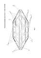
На фигуре 1 показан общий вид летательного аппарата с лопастным движителем горизонтального движения;The figure 1 shows a General view of an aircraft with a blade propulsion horizontal movement;
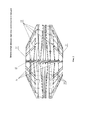
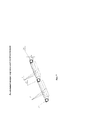
на фигуре 2 показан летательный аппарат в разрезе с двумя промежуточными лопастными движителями;figure 2 shows an aircraft in section with two intermediate blade propellers;
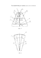
на фигуре 3 показаны лопасти из двух соседних рядов (вид изнутри);figure 3 shows the blades from two adjacent rows (inside view);
на фигуре 4 показан сегмент каркаса лопастного движителя с двумя соседними рядами лопастей (вид сверху);the figure 4 shows a segment of the frame of the blade propeller with two adjacent rows of blades (top view);
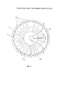
на фигуре 5 представлен летательный аппарат (вид сверху);figure 5 presents the aircraft (top view);
на фигуре 6 показан вариант выполнения летательного аппарата с верхним лопастным движителем плоской формы;figure 6 shows an embodiment of an aircraft with an upper blade propeller of a flat shape;
на фигуре 7 показано соединение лопастей, установленных в ярус.the figure 7 shows the connection of the blades installed in the tier.
На вышеуказанных фигурах элементы ЛА указаны под следующими позициями:In the above figures, the elements of the aircraft are indicated under the following positions:
1 - лопасть одного ряда верхнего лопастного движителя;1 - the blade of one row of the upper blade propeller;
2 - лопасть другого ряда верхнего лопастного движителя;2 - the blade of another row of the upper blade propeller;
3 - лопасть одного ряда нижнего лопастного движителя;3 - the blade of one row of the lower blade propeller;
4 - лопасть другого ряда нижнего лопастного движителя;4 - the blade of another row of the lower blade propeller;
5 - боковая лопасть;5 - lateral lobe;
6 - каркас верхнего лопастного движителя;6 - frame of the upper blade propeller;
7 - каркас нижнего лопастного движителя;7 - frame of the lower blade propeller;
8 - сопло РСУ;8 - nozzle DCS;
9 - воздухозаборник лопастного движителя горизонтального движения;9 - air intake blade propulsion horizontal movement;
10 - вертикальная ось летательного аппарата;10 - the vertical axis of the aircraft;
11 - малый (верхний) диск верхнего лопастного движителя;11 - small (upper) disk of the upper blade propeller;
12 - малый (нижний) диск нижнего лопастного движителя;12 - small (lower) disk of the lower blade propeller;
13 - промежуточный лопастной движитель;13 - intermediate blade propulsion;
14 - стержень;14 - a core;
15 - автомат регулировки выдвижения лопасти;15 - automatic adjustment of the extension of the blade;
16 - рычаг автомата регулировки выдвижения лопасти;16 - the lever of the automatic adjustment of the extension of the blade;
17 - автомат регулировки наклона лопасти;17 - automatic adjustment of the inclination of the blade;
18 - рычаг автомата регулировки наклона лопасти;18 - the lever of the machine for adjusting the inclination of the blade;
19 - автомат регулировки наклона боковой лопасти;19 - automatic adjustment of the inclination of the side blades;
20 - рычаг автомата регулировки наклона боковой лопасти;20 - the lever of the automatic adjustment of the inclination of the side blades;
21 - шаровая опора;21 - ball bearing;
22 - радиальная прожилина;22 - radial vein;
23 - большое кольцо каркаса;23 - a large ring frame;
24 - крыло равновесия;24 - wing of equilibrium;
25 - шаровая опора крыла равновесия;25 - ball joint of the equilibrium wing;
26 - малое кольцо каркаса;26 - a small ring of the frame;
27 - промежуточное кольцо каркаса.27 - the intermediate ring of the frame.
Предложенный летательный аппарат вертикального взлета и посадки работает следующим образом.The proposed aircraft vertical takeoff and landing operates as follows.
Запускаются воздушные двигатели реактивных силовых установок ЛА. При наборе летательным аппаратом высоты одновременно открываются лопасти 1, 2 верхнего лопастного движителя, лопасти 3, 4 нижнего лопастного движителя, а также боковые лопасти 5 верхнего и нижнего лопастного движителя. Автоматы 17 регулировки наклона лопастей посредством рычагов 18 поднимают (наклоняют) одну сторону лопастей 1, 2 верхнего лопастного движителя и лопастей 3,4 нижнего лопастного движителя, а другая сторона лопастей 1, 2 верхнего лопастного движителя и 3, 4 нижнего лопастного движителя автоматически опускается так, чтобы нагнетание воздуха произошло сверху и направлялось вниз (внутрь каркасов ЛА). Автоматы 15 регулировки выдвижения лопастей посредством рычагов 16 поднимают стержни 14 для выдвижения лопастей 1, 2 верхнего лопастного движителя и лопастей 3, 4 нижнего лопастного движителя на нужную высоту. Автоматы 19 регулировки наклона боковой лопасти посредством рычагов 20 и автоматы регулировки выдвижения боковых лопастей (на чертежах не показаны) регулируют изменение положения боковых лопастей 5 таким образом, чтобы боковые лопасти 5 нагнетали воздух сверху и направляли вниз.The air engines of the jet propulsion systems are launched. When the aircraft sets altitude, the
В случае наличия промежуточных лопастных движителей 13 при наборе ЛА высоты лопасти промежуточных лопастных движителей 13 открываются и нагнетают воздух сверху и направляют вниз. При этом верхний лопастной движитель набирает воздух сверху и подает вниз промежуточным лопастным движителям 13, которые в свою очередь подают воздух нижнему лопастному движителю, который направляет воздух вниз. Выходит воздух (в виде выхлопных газов) через вертикальные РСУ (на чертежах не показаны), увеличивая подъемную силу ЛА. Благодаря синхронной работе всех лопастных движителей ЛА легко поднимается. После того как ЛА оторвался от земли, включаются лопастные движители бокового движения. ЛА одновременно и поднимается и летит по заданному направлению. Заданное направление корректируется перепускными клапанами (на чертежах не показаны).In the case of the presence of
После набора высоты при боковом движении (движении в горизонтальной плоскости) ЛА лопасти 1, 2 верхнего лопастного движителя, лопасти 3, 4 нижнего лопастного движителя и боковые лопасти 5 могут быть задвинуты (опущены) в исходное положение. При движении горизонтально со снижением лопасти 1, 2 верхнего лопастного движителя и лопасти 3, 4 нижнего лопастного движителя и боковые лопасти 5 открываются так, чтобы встречный ветер, дующий снизу и по ходу движения ЛА, прокручивал лопастные движители, создавал сопротивление для снижения ЛА и вырабатывал электроэнергию.After climbing during lateral movement (horizontal movement) of the aircraft, the
Для поддержания необходимой высоты верхний лопастной движитель набирает воздух сверху и подает его вниз, поддерживая ЛА на необходимой высоте. При необходимости, подключаются нижний лопастной движитель, а также промежуточный лопастной движитель (или промежуточные лопастные движители, если их несколько), при этом лопастные движители переключаются на электрогенераторы и вырабатывают электричество, которое передается накопителям. Центром управления ЛА постоянно отслеживается работа всех лопастных движителей и их переход с одной на другую функцию (с электрогенераторов на двигатели и обратно), а также регулируется наклон (и/или выдвижение) лопастей на каждом лопастном движителе.To maintain the required height, the upper blade propeller gathers air from above and delivers it downward, supporting the aircraft at the required height. If necessary, the lower blade propeller is connected, as well as the intermediate blade propulsion (or intermediate blade propellers, if there are several), while the blade propellers switch to electric generators and generate electricity, which is transmitted to the drives. The control center of the aircraft constantly monitors the operation of all blade propellers and their transition from one to another function (from electric generators to engines and vice versa), and the inclination (and / or extension) of the blades on each blade propeller is also regulated.
Предложенный ЛА способен совершать аварийную посадку даже с большой высоты, оставаясь невредимым, поскольку каждый лопастной движитель обеспечен по меньшей мере одним воздушным двигателем и отдельным ресивером, которые по отдельности соединены к компрессору или нескольким компрессорам. Воздушные двигатели включаются автоматически при определенной скорости снижения и поддерживают нужную скорость при приземлении, причем двигатели обеспечены отдельной (аварийной) системой управления.The proposed aircraft is capable of making an emergency landing even from a great height, remaining unscathed, since each blade mover is provided with at least one air engine and a separate receiver, which are separately connected to a compressor or several compressors. Air engines turn on automatically at a certain descent speed and maintain the desired speed when landing, and the engines are provided with a separate (emergency) control system.
Claims (14)
Priority Applications (5)
| Application Number | Priority Date | Filing Date | Title |
|---|---|---|---|
| RU2014127730/11A RU2591103C2 (en) | 2014-07-08 | 2014-07-08 | Vertical take-off and landing aircraft |
| PCT/RU2015/000520 WO2016007049A1 (en) | 2014-07-08 | 2015-08-14 | Vertical take-off and landing aircraft |
| US15/323,757 US20170166315A1 (en) | 2014-07-08 | 2015-08-14 | Vertical take-off and landing aircraft |
| EP15819516.4A EP3168147A4 (en) | 2014-07-08 | 2015-08-14 | Vertical take-off and landing aircraft |
| EA201700013A EA201700013A1 (en) | 2014-07-08 | 2015-08-14 | AIRCRAFT VERTICAL TAKE-OFF AND LANDING |
Applications Claiming Priority (1)
| Application Number | Priority Date | Filing Date | Title |
|---|---|---|---|
| RU2014127730/11A RU2591103C2 (en) | 2014-07-08 | 2014-07-08 | Vertical take-off and landing aircraft |
Publications (2)
| Publication Number | Publication Date |
|---|---|
| RU2014127730A RU2014127730A (en) | 2016-02-10 |
| RU2591103C2 true RU2591103C2 (en) | 2016-07-10 |
Family
ID=55064556
Family Applications (1)
| Application Number | Title | Priority Date | Filing Date |
|---|---|---|---|
| RU2014127730/11A RU2591103C2 (en) | 2014-07-08 | 2014-07-08 | Vertical take-off and landing aircraft |
Country Status (5)
| Country | Link |
|---|---|
| US (1) | US20170166315A1 (en) |
| EP (1) | EP3168147A4 (en) |
| EA (1) | EA201700013A1 (en) |
| RU (1) | RU2591103C2 (en) |
| WO (1) | WO2016007049A1 (en) |
Families Citing this family (8)
| Publication number | Priority date | Publication date | Assignee | Title |
|---|---|---|---|---|
| USD1059492S1 (en) | 2020-05-28 | 2025-01-28 | Amax Group Usa, Llc | Flying toy |
| US12121826B2 (en) | 2020-05-28 | 2024-10-22 | Amax Group Usa, Llc | Hand gesture controlled flying toy |
| USD1091375S1 (en) | 2020-08-03 | 2025-09-02 | Amax Group Usa, Llc | Quadcopter |
| PL243857B1 (en) * | 2021-10-04 | 2023-10-23 | Olszewski Tymoteusz BITLAND | Method for obtaining lift and thrust for horizontal flight of a flying machine for vertical take-off and landing while maintaining horizontal flight stability of the machine and a machine for implementing this method |
| ES2880527B2 (en) * | 2021-10-05 | 2022-08-30 | Toran Manuel Bernedo | lenticular manned aerodyne |
| CN114837806B (en) * | 2022-04-19 | 2023-11-21 | 李久斌 | a flat jet engine |
| USD1035787S1 (en) * | 2022-06-24 | 2024-07-16 | Amax Group Usa, Llc | Flying toy |
| USD1036559S1 (en) * | 2022-06-30 | 2024-07-23 | Urban Sky Theory Inc. | Balloon |
Citations (2)
| Publication number | Priority date | Publication date | Assignee | Title |
|---|---|---|---|---|
| US5064143A (en) * | 1989-04-19 | 1991-11-12 | Sky Disk Holding Sa | Aircraft, having a pair of counter rotating rotors |
| RU2520263C2 (en) * | 2008-05-30 | 2014-06-20 | Джило Индастриз Лимитед | Aircraft with two opposite-rotation propellers fitted on vertical shaft |
Family Cites Families (10)
| Publication number | Priority date | Publication date | Assignee | Title |
|---|---|---|---|---|
| US2377835A (en) * | 1944-01-01 | 1945-06-05 | Weygers Alexander George | Discopter |
| US2935275A (en) * | 1955-10-20 | 1960-05-03 | Leonard W Grayson | Disc shaped aircraft |
| US3002709A (en) * | 1955-12-19 | 1961-10-03 | C L Cochran And Associates | Aircraft adapted for vertical ascent and descent |
| US2996269A (en) * | 1956-04-12 | 1961-08-15 | Charles B Bolton | Helicopter with counter-rotating propeller |
| DE2352484A1 (en) * | 1973-10-19 | 1975-04-30 | Messerschmitt Boelkow Blohm | Rotary wing with jet drive - has small low pressure jet plant mounted in the hub section of the wing |
| SU1817755A3 (en) * | 1990-06-09 | 1993-05-23 | Anatolij V Isaev | Vertical take off and landing flying apparatus |
| DE10014899A1 (en) * | 2000-03-24 | 2001-09-27 | Helmut Richter | Annular wing all-weather aircraft has drive-creating part fixed to horizontal axes connected to wing rings |
| AU2001274840A1 (en) * | 2000-05-15 | 2001-11-26 | Sunlase, Inc. | Aircraft and hybrid with magnetic airfoil suspension and drive |
| US20040094662A1 (en) * | 2002-01-07 | 2004-05-20 | Sanders John K. | Vertical tale-off landing hovercraft |
| RU2497721C2 (en) * | 2011-11-01 | 2013-11-10 | Фатидин Абдурахманович Мухамедов | Mukhamedov's vtol aircraft with jump landing gear |
-
2014
- 2014-07-08 RU RU2014127730/11A patent/RU2591103C2/en not_active IP Right Cessation
-
2015
- 2015-08-14 EA EA201700013A patent/EA201700013A1/en unknown
- 2015-08-14 WO PCT/RU2015/000520 patent/WO2016007049A1/en not_active Ceased
- 2015-08-14 US US15/323,757 patent/US20170166315A1/en not_active Abandoned
- 2015-08-14 EP EP15819516.4A patent/EP3168147A4/en not_active Withdrawn
Patent Citations (2)
| Publication number | Priority date | Publication date | Assignee | Title |
|---|---|---|---|---|
| US5064143A (en) * | 1989-04-19 | 1991-11-12 | Sky Disk Holding Sa | Aircraft, having a pair of counter rotating rotors |
| RU2520263C2 (en) * | 2008-05-30 | 2014-06-20 | Джило Индастриз Лимитед | Aircraft with two opposite-rotation propellers fitted on vertical shaft |
Also Published As
| Publication number | Publication date |
|---|---|
| RU2014127730A (en) | 2016-02-10 |
| EP3168147A4 (en) | 2017-12-13 |
| EA201700013A1 (en) | 2017-05-31 |
| WO2016007049A1 (en) | 2016-01-14 |
| EP3168147A1 (en) | 2017-05-17 |
| US20170166315A1 (en) | 2017-06-15 |
Similar Documents
| Publication | Publication Date | Title |
|---|---|---|
| RU2591103C2 (en) | Vertical take-off and landing aircraft | |
| RU2363621C2 (en) | Flight vehicle (versions) | |
| RU2520263C2 (en) | Aircraft with two opposite-rotation propellers fitted on vertical shaft | |
| US20130140404A1 (en) | System and method for improving transition lift-fan performance | |
| US20030127559A1 (en) | Circular vertical take off & landing aircraft | |
| US20130205941A1 (en) | Horizontal attitude stabilization device for disc air vehicle | |
| US20210331797A1 (en) | Flying saucer aircraft | |
| WO2024222904A1 (en) | Aerial vehicle | |
| US20180037319A1 (en) | Vertical take-off and landing aircraft (variants) | |
| US3041009A (en) | Aircraft | |
| CN106364665A (en) | Flight power system and flight vehicle | |
| RU2214945C1 (en) | Flying vehicle | |
| EP4412902B1 (en) | Vertical take-off and landing (vtol) flying machine and its operation method | |
| EP4111052B1 (en) | Toroidal lift force engine | |
| RU2816381C1 (en) | Helicopter-platform with ground effect | |
| RU2548294C2 (en) | Atmospheric flying saucer (versions) | |
| RU2687533C1 (en) | Rotary-winged aircraft with screen effect | |
| RU2810988C1 (en) | Vertical take-off and landing aircraft | |
| US1966461A (en) | Rotary vacuum wing or propeller for use on air, land, and water vehicles | |
| RU2009124298A (en) | METHOD OF FLIGHT IN AIR WITH THE POSSIBILITY OF VERTICAL TAKEOFF AND LANDING AND ROTOROPLAN WITH VERTICAL TAKEOFF AND LANDING | |
| RU2723564C2 (en) | Helicopter equipped with lifting force emergency device | |
| RU2566177C2 (en) | Device and method for flight through air with possibility of vertical takeoff and landing | |
| RU2511735C1 (en) | Vertical take-off and landing drone | |
| US1208684A (en) | Method of aerial navigation. | |
| RU133808U1 (en) | COMBINED AIRCRAFT |
Legal Events
| Date | Code | Title | Description |
|---|---|---|---|
| MM4A | The patent is invalid due to non-payment of fees |
Effective date: 20170709 |